2000 NISSAN PATROL stop start
[x] Cancel search: stop startPage 440 of 1033
Description
SYSTEM DESCRIPTION
Sensor Input Signal to ECM ECM Function Actuator
Electronic controlled fuel injection pump Fuel injection signal
EGR volume control EGR volume control valve Crankshaft position sensor (TDC) Engine speed
Vehicle speed sensor Vehicle speed
Engine coolant temperature sensor Engine coolant temperature
Ignition switch Start signal
Throttle position sensor Throttle position
Battery Battery voltage
Mass air flow sensor Amount of intake air
Air conditioner switch Air conditioner operation
Electrical load Electrical load signal
PNP switch Park/Neutral position signal
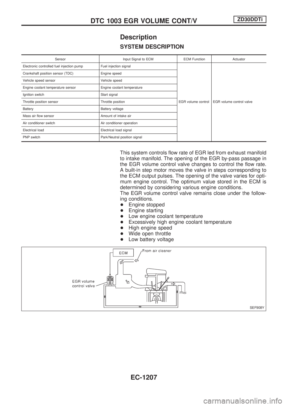
This system controls flow rate of EGR led from exhaust manifold
to intake manifold. The opening of the EGR by-pass passage in
the EGR volume control valve changes to control the flow rate.
A built-in step motor moves the valve in steps corresponding to
the ECM output pulses. The opening of the valve varies for opti-
mum engine control. The optimum value stored in the ECM is
determined by considering various engine conditions.
The EGR volume control valve remains close under the follow-
ing conditions.
+Engine stopped
+Engine starting
+Low engine coolant temperature
+Excessively high engine coolant temperature
+High engine speed
+Wide open throttle
+Low battery voltage
SEF908Y
DTC 1003 EGR VOLUME CONT/VZD30DDTi
EC-1207
Page 511 of 1033
ELECTRICAL SYSTEM
SECTION
EL
When you read wiring diagrams:
+Read GI section, ªHOW TO READ WIRING DIAGRAMSº.
When you perform trouble diagnoses, read GI section, ªHOW TO FOLLOW FLOW
CHART IN TROUBLE DIAGNOSESº and ªHOW TO PERFORM EFFICIENT DIAGNOSIS
FOR AN ELECTRICAL INCIDENTº.
+Check for any service bulletins before servicing the vehicle.
MODIFICATION NOTICE:
+Power window (driver's side only) with an interruption detection function has been adopted.
+ID code entry procedure of multi-remote control system has been changed.
+NATS (Nissan Anti-Theft System) has been adopted on ZD engine model.
CONTENTS
PRECAUTIONS AND PREPARATION............... 1003
Supplemental Restraint System (SRS) ªAIR
BAGº and ªSEAT BELT PRE-TENSIONERº ... 1003
POWER SUPPLY ROUTING............................... 1004
Schematic ........................................................ 1004
Wiring Diagram Ð POWER Ð ........................ 1005
GROUND DISTRIBUTION/LHD MODELS.......... 1013
Engine Room Harness..................................... 1013
Engine Control Harness................................... 1016
Main Harness ................................................... 1017
Body Harness .................................................. 1020
Body No. 2 Harness ........................................ 1022
Back Door and Rear Window Defogger
Harness ............................................................ 1023
GROUND DISTRIBUTION/RHD MODELS......... 1024
Engine Room Harness..................................... 1024
Engine Control Harness................................... 1027
Main Harness ................................................... 1028
Body Harness .................................................. 1031
Body No. 2 Harness ........................................ 1033
Back Door and Rear Window Defogger
Harness ............................................................ 1034
BATTERY............................................................. 1035
Service Data and Specifications (SDS) ........... 1035
STARTING SYSTEM........................................... 1036
Wiring Diagram Ð START Ð/M/T Models...... 1036
Wiring Diagram Ð START Ð/A/T Models ...... 1037
Construction ..................................................... 1038Service Data and Specifications (SDS) ........... 1039
CHARGING SYSTEM.......................................... 1040
Wiring Diagram Ð CHARGE ........................... 1040
Construction ..................................................... 1041
Service Data and Specifications (SDS) ........... 1041
COMBINATION SWITCH.................................... 1042
Check ............................................................... 1042
STEERING SWITCH............................................ 1043
Check ............................................................... 1043
HEADLAMP Ð Daytime Light System Ð........ 1044
Wiring Diagram Ð DTRL Ð ............................ 1044
PARKING, LICENSE AND TAIL LAMPS........... 1046
Wiring Diagram Ð TAIL/L Ð/LHD Models ...... 1046
Wiring Diagram Ð TAIL/L Ð/RHD Models ..... 1048
STOP LAMP........................................................ 1050
Wiring Diagram Ð STOP/L Ð......................... 1050
BACK-UP LAMP.................................................. 1051
Wiring Diagram Ð BACK/L Ð/RHD Models ... 1051
FRONT FOG LAMP............................................. 1052
Wiring Diagram Ð F/FOG Ð .......................... 1052
REAR FOG LAMP............................................... 1053
Wiring Diagram Ð R/FOG Ð .......................... 1053
CORNERING LAMP............................................ 1054
Wiring Diagram Ð CORNER Ð/LHD Models . 1054
System Description/RHD Models .................... 1055
Wiring Diagram Ð CORNER Ð/RHD Models1056
Trouble Diagnoses/RHD Models ..................... 1057
EL
Page 549 of 1033
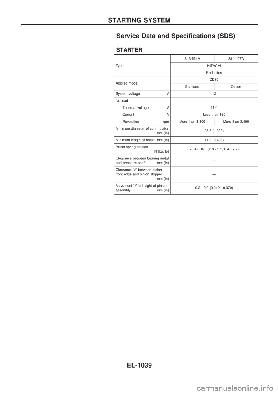
Service Data and Specifications (SDS)
STARTER
TypeS13-551A S14-407A
HITACHI
Reduction
Applied modelZD30
Standard Option
System voltage V 12
No-load
Terminal voltage V 11.0
Current A Less than 160
Revolution rpm More than 3,300 More than 3,400
Minimum diameter of commutator
mm (in)35.5 (1.398)
Minimum length of brush mm (in) 11.0 (0.433)
Brush spring tension
N (kg, lb)28.4 - 34.3 (2.9 - 3.5, 6.4 - 7.7)
Clearance between bearing metal
and armature shaft mm (in)Ð
Clearance ª!º between pinion
front edge and pinion stopper
mm (in)Ð
Movement ª!º in height of pinion
assembly mm (in)0.3 - 2.0 (0.012 - 0.079)
STARTING SYSTEM
EL-1039
Page 737 of 1033
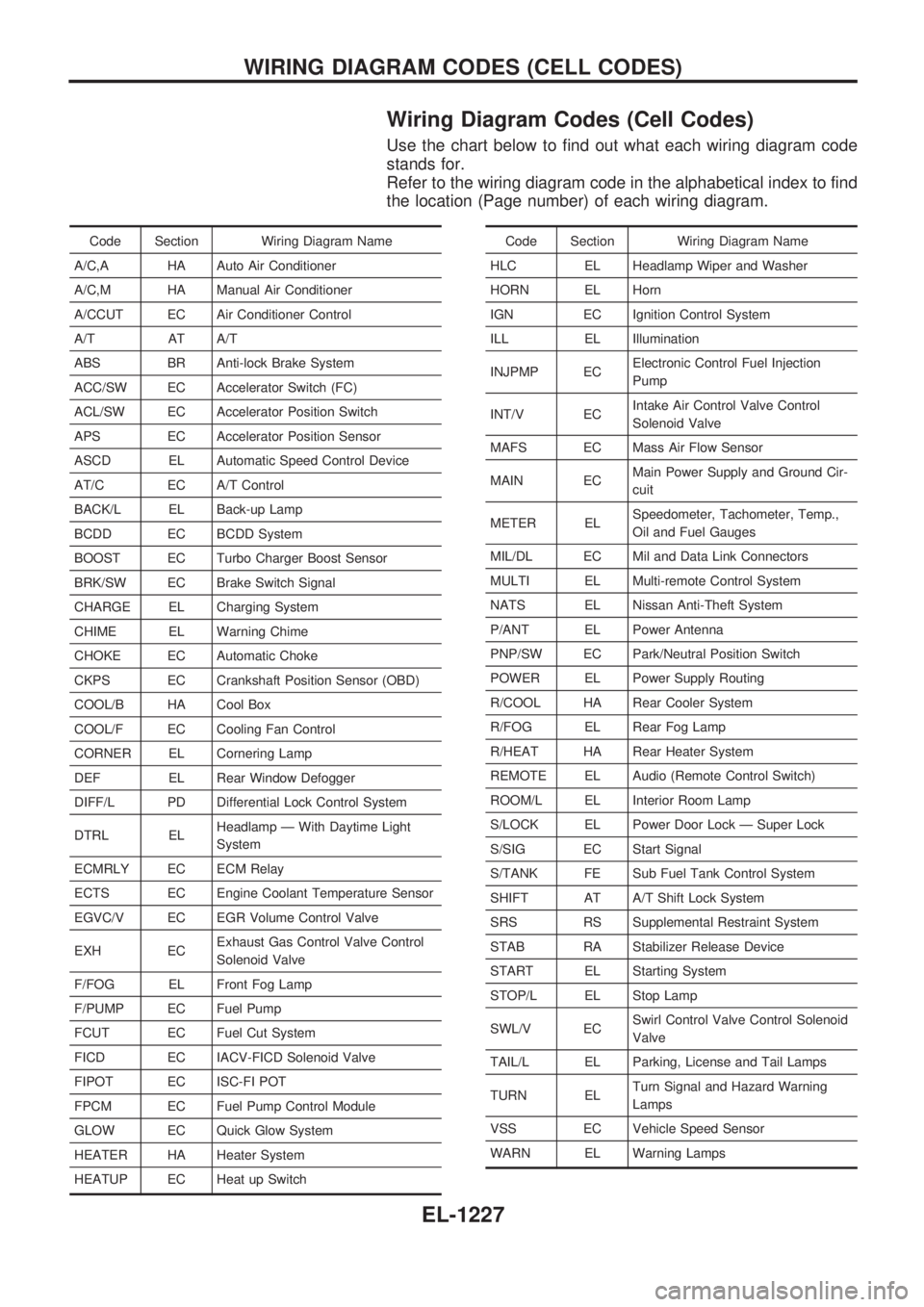
Wiring Diagram Codes (Cell Codes)
Use the chart below to find out what each wiring diagram code
stands for.
Refer to the wiring diagram code in the alphabetical index to find
the location (Page number) of each wiring diagram.
Code Section Wiring Diagram Name
A/C,A HA Auto Air Conditioner
A/C,M HA Manual Air Conditioner
A/CCUT EC Air Conditioner Control
A/T AT A/T
ABS BR Anti-lock Brake System
ACC/SW EC Accelerator Switch (FC)
ACL/SW EC Accelerator Position Switch
APS EC Accelerator Position Sensor
ASCD EL Automatic Speed Control Device
AT/C EC A/T Control
BACK/L EL Back-up Lamp
BCDD EC BCDD System
BOOST EC Turbo Charger Boost Sensor
BRK/SW EC Brake Switch Signal
CHARGE EL Charging System
CHIME EL Warning Chime
CHOKE EC Automatic Choke
CKPS EC Crankshaft Position Sensor (OBD)
COOL/B HA Cool Box
COOL/F EC Cooling Fan Control
CORNER EL Cornering Lamp
DEF EL Rear Window Defogger
DIFF/L PD Differential Lock Control System
DTRL ELHeadlamp Ð With Daytime Light
System
ECMRLY EC ECM Relay
ECTS EC Engine Coolant Temperature Sensor
EGVC/V EC EGR Volume Control Valve
EXH ECExhaust Gas Control Valve Control
Solenoid Valve
F/FOG EL Front Fog Lamp
F/PUMP EC Fuel Pump
FCUT EC Fuel Cut System
FICD EC IACV-FICD Solenoid Valve
FIPOT EC ISC-FI POT
FPCM EC Fuel Pump Control Module
GLOW EC Quick Glow System
HEATER HA Heater System
HEATUP EC Heat up SwitchCode Section Wiring Diagram Name
HLC EL Headlamp Wiper and Washer
HORN EL Horn
IGN EC Ignition Control System
ILL EL Illumination
INJPMP ECElectronic Control Fuel Injection
Pump
INT/V ECIntake Air Control Valve Control
Solenoid Valve
MAFS EC Mass Air Flow Sensor
MAIN ECMain Power Supply and Ground Cir-
cuit
METER ELSpeedometer, Tachometer, Temp.,
Oil and Fuel Gauges
MIL/DL EC Mil and Data Link Connectors
MULTI EL Multi-remote Control System
NATS EL Nissan Anti-Theft System
P/ANT EL Power Antenna
PNP/SW EC Park/Neutral Position Switch
POWER EL Power Supply Routing
R/COOL HA Rear Cooler System
R/FOG EL Rear Fog Lamp
R/HEAT HA Rear Heater System
REMOTE EL Audio (Remote Control Switch)
ROOM/L EL Interior Room Lamp
S/LOCK EL Power Door Lock Ð Super Lock
S/SIG EC Start Signal
S/TANK FE Sub Fuel Tank Control System
SHIFT AT A/T Shift Lock System
SRS RS Supplemental Restraint System
STAB RA Stabilizer Release Device
START EL Starting System
STOP/L EL Stop Lamp
SWL/V ECSwirl Control Valve Control Solenoid
Valve
TAIL/L EL Parking, License and Tail Lamps
TURN ELTurn Signal and Hazard Warning
Lamps
VSS EC Vehicle Speed Sensor
WARN EL Warning Lamps
WIRING DIAGRAM CODES (CELL CODES)
EL-1227
Page 775 of 1033
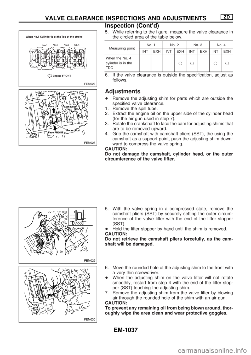
5. While referring to the figure, measure the valve clearance in
the circled area of the table below.
Measuring pointNo. 1 No. 2 No. 3 No. 4
INT EXH INT EXH INT EXH INT EXH
When the No. 4
cylinder is in the
TDCjj jj
6. If the valve clearance is outside the specification, adjust as
follows.
Adjustments
+Remove the adjusting shim for parts which are outside the
specified valve clearance.
1. Remove the spill tube.
2. Extract the engine oil on the upper side of the cylinder head
(for the air gun used in step 7).
3. Rotate the crankshaft to face the cam for adjusting shims that
are to be removed upward.
4. Grip the camshaft with camshaft pliers (SST), the using the
camshaft as a support point, push the adjusting shim down-
ward to compress the valve spring.
CAUTION:
Do not damage the camshaft, cylinder head, or the outer
circumference of the valve lifter.
5. With the valve spring in a compressed state, remove the
camshaft pliers (SST) by securely setting the outer circum-
ference of the valve lifter with the end of the lifter stopper
(SST).
+Hold the lifter stopper by hand until the shim is removed.
CAUTION:
Do not retrieve the camshaft pliers forcefully, as the cam-
shaft will be damaged.
6. Move the rounded hole of the adjusting shim to the front with
a very thin screwdriver.
+When the adjusting shim on the valve lifter will not rotate
smoothly, restart from step 4 with the end of the lifter stop-
per (SST) touching the adjusting shim.
7. Remove the adjusting shim from the valve lifter by blowing
air through the rounded hole of the shim with an air gun.
CAUTION:
To prevent any remaining oil from being blown around, thor-
oughly wipe the area clean and wear protective goggles.
FEM027
FEM028
FEM029
FEM030
VALVE CLEARANCE INSPECTIONS AND ADJUSTMENTSZD
Inspection (Cont'd)
EM-1037
Page 779 of 1033
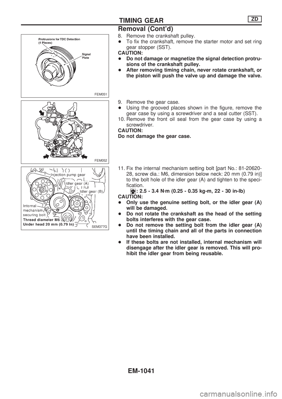
8. Remove the crankshaft pulley.
+To fix the crankshaft, remove the starter motor and set ring
gear stopper (SST).
CAUTION:
+Do not damage or magnetize the signal detection protru-
sions of the crankshaft pulley.
+After removing timing chain, never rotate crankshaft, or
the piston will push the valve up and damage the valve.
9. Remove the gear case.
+Using the grooved places shown in the figure, remove the
gear case by using a screwdriver and a seal cutter (SST).
10. Remove the front oil seal from the gear case by using a
screwdriver.
CAUTION:
Do not damage the gear case.
11. Fix the internal mechanism setting bolt [part No.: 81-20620-
28, screw dia.: M6, dimension below neck: 20 mm (0.79 in)]
to the bolt hole of the idler gear (A) and tighten to the speci-
fication.
: 2.5 - 3.4 Nzm (0.25 - 0.35 kg-m, 22 - 30 in-lb)
CAUTION:
+Only use the genuine setting bolt, or the idler gear (A)
will be damaged.
+Do not rotate the crankshaft as the head of the setting
bolts interferes with the gear case.
+Do not remove the setting bolt from the idler gear (A)
until the timing chain and all of the parts in connection
have been installed.
+If these bolts are not installed, internal mechanism will
disengage after the idler gear is removed. This will pro-
hibit the idler gear from being reusable.
FEM051
FEM052
SEM377G
TIMING GEARZD
Removal (Cont'd)
EM-1041
Page 882 of 1033
O
Oil change (capacity) ............................ MA-1008
Oil pan (engine) .................................... EM-1022
Oil pump (A/T) ....................................... AT-1144
Oil seal replacement (engine) .............. EM-1051
On board diagnostic system ................. EC-1032
Operating cylinder (clutch) .................... CL-1003
Outside mirror ........................................ BT-1007
Overdrive control switch ........................ AT-1095
Overrun clutch solenoid valve ............... AT-1075
Overrun clutch ....................................... AT-1167
Oversize piston ..................................... EM-1075
P
P/ANT - Wiring diagram ........................ EL-1109
PCV (positive crankcase ventilation) .... EC-1022
PNP/SW - Wiring diagram .................... EC-1233
POWER - Wiring diagram ..................... EL-1005
Park/Neutral position switch ................. EC-1233
Park/neutral position switch (A/T) ......... AT-1095
Parking lamp .......................................... EL-1046
Pilot bushing replacement - See Pilot
converter ........................................... EM-1083
Piston pin inspection ............................ EM-1072
Piston ring inspection ........................... EM-1073
Piston to bore clearance ...................... EM-1076
Power antenna ...................................... EL-1109
Power supply routing ............................. EL-1004
Power window ....................................... EL-1115
Pressure test (A/T) ................................ AT-1044
Priming pump ........................................ EC-1049
Propeller shaft on vehicle service ......... PD-1003
Propeller shaft vibration ........................ PD-1003
Propeller shaft ....................................... PD-1002
Q
Quick-glow system ................................ EC-1221
R
R/COOL - Wiring diagram
(front auto A/C) ....................... HA-1013, 1017
R/COOL - Wiring diagram (front
manual A/C) ...................................... HA-1019
R/HEAT - Wiring diagram ..................... HA-1006
ROOM/L - Wiring diagram ..................... EL-1068
Radio - See Audio ................................. EL-1108
Rear cooler - Wiring diagram (front
auto A/C) ................................. HA-1013, 1017
Rear cooler - Wiring diagram (front
manual A/C) ...................................... HA-1019
Rear fog lamp ........................................ EL-1053
Rear heater - Wiring diagram ............... HA-1006Rear window defogger .......................... EL-1101
Refrigerant lines .................................... HA-1021
Removal and installation (A/T) .............. AT-1127
Reverse clutch ....................................... AT-1161
Revolution sensor (A/T) ........................ AT-1065
Room lamp - See Interior lamp ............. EL-1067
S
S/LOCK - Wiring diagram ...................... EL-1128
S/TANK - Wiring diagram ...................... FE-1003
SHIFT - Wiring diagram ........................ AT-1117
SRS - See Supplemental Restraint
System .............................................. RS-1003
STAB - Wiring diagram ......................... RA-1002
START - Wiring diagram ....................... EL-1036
SWL/V - Wiring diagram ....................... EC-1248
Screw jack .............................................. GI-1009
Seat belt pre-tensioner disposal ........... RS-1015
Seat belt pre-tensioner ......................... RS-1003
Seat, front .............................................. BT-1006
Self-diagnostic results ........................... EC-1034
Shift lock system ................................... AT-1116
Shift schedule ........................................ AT-1206
Shift solenoid valve A (A/T) .................. AT-1071
Shift solenoid valve B (A/T) .................. AT-1073
Side air bag ........................................... RS-1003
Speedometer ......................................... EL-1073
Spiral cable ........................................... RS-1009
Stabilizer release device - Wiring
diagram ............................................. RA-1002
Stabilizer release device ....................... RA-1002
Stall test (A/T) ....................................... AT-1041
Start signal ............................................ EC-1230
Starter .................................................... EL-1039
Starting system ...................................... EL-1036
Steering switch ...................................... EL-1043
Stop lamp .............................................. EL-1050
Super lock ................................... EL-1124, 1159
Supplemental Restraint System ........... RS-1003
Supplemental restraint system - Wiring
diagram ................................... RS-1024, 1028
Swirl control valve control solenoid
valve .................................................. EC-1246
Symptom matrix chart ........................... EC-1055
T
TCM circuit diagram .............................. AT-1008
TCM inspection table ............................ AT-1060
Tachometer ............................................ EL-1073
Tail lamp ................................................ EL-1046
Throttle position switch .......................... AT-1096
Timing chain ......................................... EM-1027
Timing gear ........................................... EM-1039
Torque converter clutch solenoid
valve .................................................. AT-1078
Torque converter installation ................. AT-1128
ALPHABETICAL INDEX
IDX-1004
Page 910 of 1033
Removal
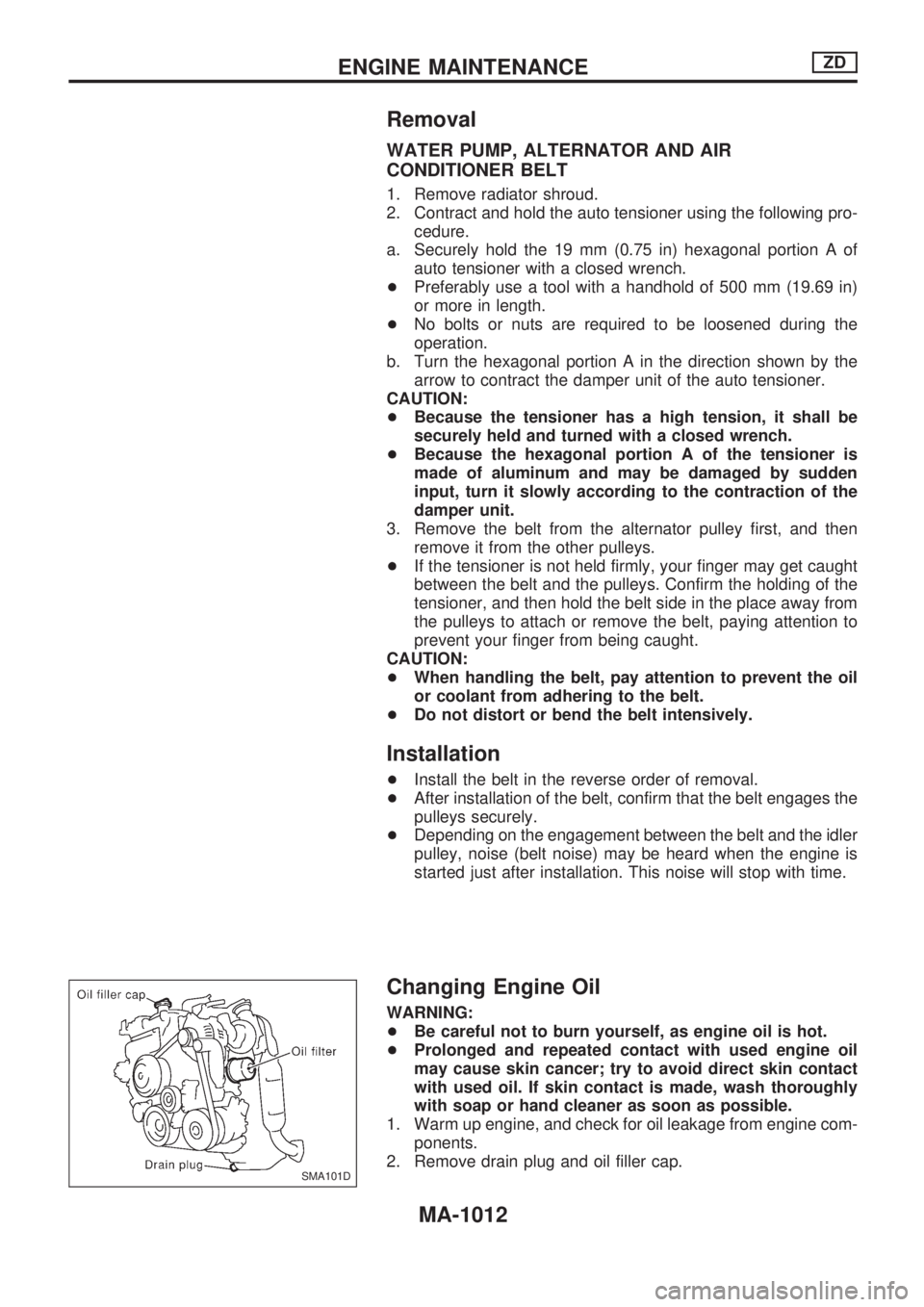
WATER PUMP, ALTERNATOR AND AIR
CONDITIONER BELT
1. Remove radiator shroud.
2. Contract and hold the auto tensioner using the following pro-
cedure.
a. Securely hold the 19 mm (0.75 in) hexagonal portion A of
auto tensioner with a closed wrench.
+Preferably use a tool with a handhold of 500 mm (19.69 in)
or more in length.
+No bolts or nuts are required to be loosened during the
operation.
b. Turn the hexagonal portion A in the direction shown by the
arrow to contract the damper unit of the auto tensioner.
CAUTION:
+Because the tensioner has a high tension, it shall be
securely held and turned with a closed wrench.
+Because the hexagonal portion A of the tensioner is
made of aluminum and may be damaged by sudden
input, turn it slowly according to the contraction of the
damper unit.
3. Remove the belt from the alternator pulley first, and then
remove it from the other pulleys.
+If the tensioner is not held firmly, your finger may get caught
between the belt and the pulleys. Confirm the holding of the
tensioner, and then hold the belt side in the place away from
the pulleys to attach or remove the belt, paying attention to
prevent your finger from being caught.
CAUTION:
+When handling the belt, pay attention to prevent the oil
or coolant from adhering to the belt.
+Do not distort or bend the belt intensively.
Installation
+Install the belt in the reverse order of removal.
+After installation of the belt, confirm that the belt engages the
pulleys securely.
+Depending on the engagement between the belt and the idler
pulley, noise (belt noise) may be heard when the engine is
started just after installation. This noise will stop with time.
Changing Engine Oil
WARNING:
+Be careful not to burn yourself, as engine oil is hot.
+Prolonged and repeated contact with used engine oil
may cause skin cancer; try to avoid direct skin contact
with used oil. If skin contact is made, wash thoroughly
with soap or hand cleaner as soon as possible.
1. Warm up engine, and check for oil leakage from engine com-
ponents.
2. Remove drain plug and oil filler cap.
SMA101D
ENGINE MAINTENANCEZD
MA-1012