2000 NISSAN PATROL steering wheel
[x] Cancel search: steering wheelPage 902 of 1033
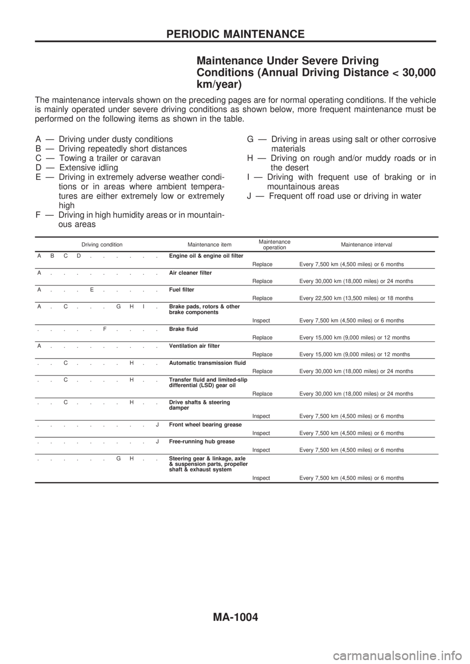
Maintenance Under Severe Driving
Conditions (Annual Driving Distance < 30,000
km/year)
The maintenance intervals shown on the preceding pages are for normal operating conditions. If the vehicle
is mainly operated under severe driving conditions as shown below, more frequent maintenance must be
performed on the following items as shown in the table.
A Ð Driving under dusty conditions
B Ð Driving repeatedly short distances
C Ð Towing a trailer or caravan
D Ð Extensive idling
E Ð Driving in extremely adverse weather condi-
tions or in areas where ambient tempera-
tures are either extremely low or extremely
high
F Ð Driving in high humidity areas or in mountain-
ous areasG Ð Driving in areas using salt or other corrosive
materials
H Ð Driving on rough and/or muddy roads or in
the desert
I Ð Driving with frequent use of braking or in
mountainous areas
J Ð Frequent off road use or driving in water
Driving condition Maintenance itemMaintenance
operationMaintenance interval
ABCD......Engine oil & engine oil filter
Replace Every 7,500 km (4,500 miles) or 6 months
A.........Air cleaner filter
Replace Every 30,000 km (18,000 miles) or 24 months
A...E.....Fuel filter
Replace Every 22,500 km (13,500 miles) or 18 months
A.C...GHI.Brake pads, rotors & other
brake components
Inspect Every 7,500 km (4,500 miles) or 6 months
.....F....Brake fluid
Replace Every 15,000 km (9,000 miles) or 12 months
A.........Ventilation air filter
Replace Every 15,000 km (9,000 miles) or 12 months
..C....H..Automatic transmission fluid
Replace Every 30,000 km (18,000 miles) or 24 months
..C....H..Transfer fluid and limited-slip
differential (LSD) gear oil
Replace Every 30,000 km (18,000 miles) or 24 months
..C....H..Drive shafts & steering
damper
Inspect Every 7,500 km (4,500 miles) or 6 months
.........JFront wheel bearing grease
Inspect Every 7,500 km (4,500 miles) or 6 months
.........JFree-running hub grease
Inspect Every 7,500 km (4,500 miles) or 6 months
......GH..Steering gear & linkage, axle
& suspension parts, propeller
shaft & exhaust system
Inspect Every 7,500 km (4,500 miles) or 6 months
PERIODIC MAINTENANCE
MA-1004
Page 904 of 1033
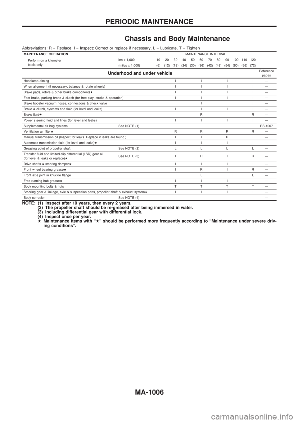
Chassis and Body Maintenance
Abbreviations: R = Replace, I = Inspect: Correct or replace if necessary, L = Lubricate, T = Tighten
MAINTENANCE OPERATIONMAINTENANCE INTERVAL
Perform on a kilometer
basis onlykm x 1,000 10 20 30 40 50 60 70 80 90 100 110 120
(miles x 1,000) (6) (12) (18) (24) (30) (36) (42) (48) (54) (60) (66) (72)
Underhood and under vehicleReference
pages
Headlamp aimingIIIIÐ
When alignment (if necessary, balance & rotate wheels)IIIIÐ
Brake pads, rotors & other brake componentsHIIIIÐ
Foot brake, parking brake & clutch (for free play, stroke & operation)IIIIÐ
Brake booster vacuum hoses, connections & check valve I I Ð
Brake & clutch, systems and fluid (for level and leaks)IIIIÐ
Brake fluidHRRÐ
Power steering fluid and lines (for level and leaks)IIIIÐ
Supplemental air bag systems See NOTE (1)RS-1007
Ventilation air filterHRRRRÐ
Manual transmission oil (Inspect for leaks. Replace if leaks are found.) I I R I Ð
Automatic transmission fluid (for level and leaks)HIIIIÐ
Greasing point of propeller shaft See NOTE (2)LLLLÐ
Transfer fluid and limited-slip differential (LSD) gear oil
(for level & leaks or replace)HSee NOTE (3) I R I R Ð
Drive shafts & steering damperHIIIIÐ
Front wheel bearing greaseHIRIRÐ
Front axle joint in knuckle flangeLLÐ
Free-running hub greaseHIIIIÐ
Body mounting bolts & nutsTTTTÐ
Steering gear & linkage, axle & suspension parts, propeller shaft & exhaust systemHIIIIÐ
Body corrosion See NOTE (4)Ð
NOTE: (1) Inspect after 10 years, then every 2 years.
(2) The propeller shaft should be re-greased after being immersed in water.
(3) Including differential gear with differential lock.
(4) Inspect once per year.
HMaintenance items with ªHº should be performed more frequently according to ªMaintenance under severe driv-
ing conditionsº.
PERIODIC MAINTENANCE
MA-1006
Page 905 of 1033
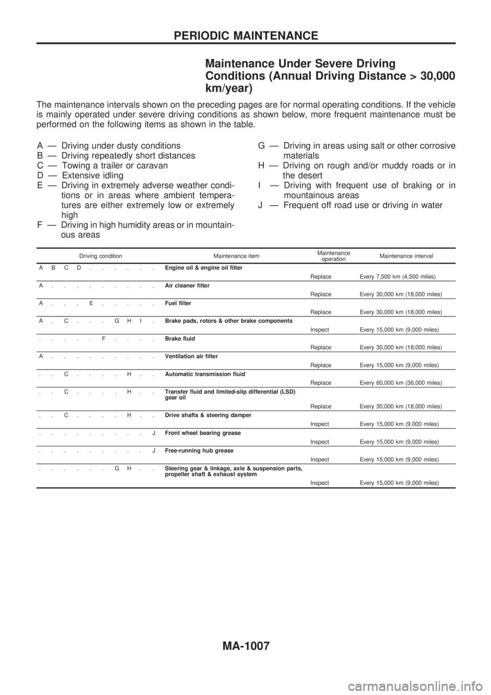
MaintenanceUnderSevereDriving
Conditions (Annual Driving Distance > 30,000
km/year)
The maintenance intervals shown on the preceding pages are for normal operating conditions. If the vehicle
is mainly operated under severe driving conditions as shown below, more frequent maintenance must be
performed on the following items as shown in the table.
A Ð Driving under dusty conditions
B Ð Driving repeatedly short distances
C Ð Towing a trailer or caravan
D Ð Extensive idling
E Ð Driving in extremely adverse weather condi- tions or in areas where ambient tempera-
tures are either extremely low or extremely
high
F Ð Driving in high humidity areas or in mountain- ous areas G Ð Driving in areas using salt or other corrosive
materials
H Ð Driving on rough and/or muddy roads or in the desert
I Ð Driving with frequent use of braking or in mountainous areas
J Ð Frequent off road use or driving in water
Driving condition Maintenance item Maintenance
operation Maintenance interval
ABCD...... Engine oil & engine oil filter
Replace Every 7,500 km (4,500 miles)
A......... Air cleaner filter
Replace Every 30,000 km (18,000 miles)
A...E..... Fuel filter
Replace Every 30,000 km (18,000 miles)
A.C...GHI. Brake pads, rotors & other brake components
Inspect Every 15,000 km (9,000 miles)
.....F.... Brake fluid
Replace Every 30,000 km (18,000 miles)
A......... Ventilation air filter
Replace Every 15,000 km (9,000 miles)
..C....H.. Automatic transmission fluid
Replace Every 60,000 km (36,000 miles)
..C....H.. Transfer fluid and limited-slip differential (LSD)
gear oil
Replace Every 30,000 km (18,000 miles)
..C....H.. Drive shafts & steering damper
Inspect Every 15,000 km (9,000 miles)
.........J Front wheel bearing grease
Inspect Every 15,000 km (9,000 miles)
.........J Free-running hub grease
Inspect Every 15,000 km (9,000 miles)
......GH.. Steering gear & linkage, axle & suspension parts,
propeller shaft & exhaust system
Inspect Every 15,000 km (9,000 miles)
PERIODIC MAINTENANCE
MA-1007
Page 974 of 1033
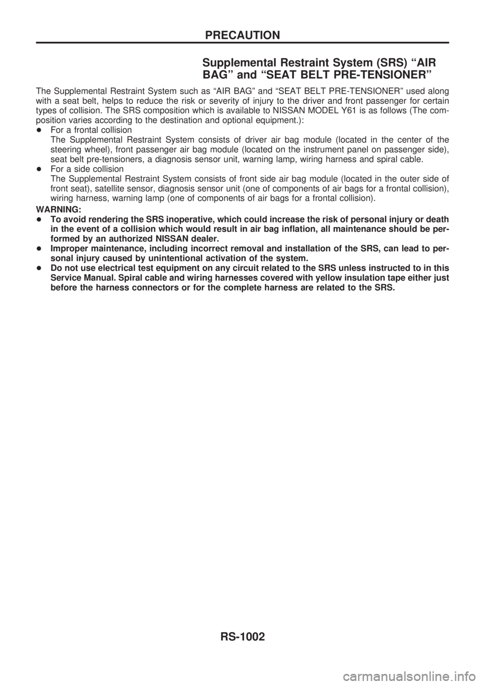
Supplemental Restraint System (SRS) ªAIR
BAGº and ªSEAT BELT PRE-TENSIONERº
The Supplemental Restraint System such as ªAIR BAGº and ªSEAT BELT PRE-TENSIONERº used along
with a seat belt, helps to reduce the risk or severity of injury to the driver and front passenger for certain
types of collision. The SRS composition which is available to NISSAN MODEL Y61 is as follows (The com-
position varies according to the destination and optional equipment.):
+For a frontal collision
The Supplemental Restraint System consists of driver air bag module (located in the center of the
steering wheel), front passenger air bag module (located on the instrument panel on passenger side),
seat belt pre-tensioners, a diagnosis sensor unit, warning lamp, wiring harness and spiral cable.
+For a side collision
The Supplemental Restraint System consists of front side air bag module (located in the outer side of
front seat), satellite sensor, diagnosis sensor unit (one of components of air bags for a frontal collision),
wiring harness, warning lamp (one of components of air bags for a frontal collision).
WARNING:
+To avoid rendering the SRS inoperative, which could increase the risk of personal injury or death
in the event of a collision which would result in air bag inflation, all maintenance should be per-
formed by an authorized NISSAN dealer.
+Improper maintenance, including incorrect removal and installation of the SRS, can lead to per-
sonal injury caused by unintentional activation of the system.
+Do not use electrical test equipment on any circuit related to the SRS unless instructed to in this
Service Manual. Spiral cable and wiring harnesses covered with yellow insulation tape either just
before the harness connectors or for the complete harness are related to the SRS.
PRECAUTION
RS-1002
Page 975 of 1033
Precautions for SRS ªAIR BAGº and ªSEAT
BELT PRE-TENSIONERº Service
+Do not use electrical test equipment to check SRS circuits unless instructed to in this Service Manual.
+Before servicing the SRS, turn ignition switch ªOFFº, disconnect both battery cables and wait at least 3
minutes.
For approximately 3 minutes after the cables are removed, it is still possible for the air bag and seat belt pre-
tensioner to deploy. Therefore, do not work on any SRS connectors or wires until at least 3 minutes have passed.
+Diagnosis sensor unit must always be installed with their arrow marks ªSº pointing towards the front of
the vehicle for proper operation. Also check diagnosis sensor unit for cracks, deformities or rust before
installation and replace as required.
+The spiral cable must be aligned with the neutral position since its rotations are limited. Do not attempt
to turn steering wheel or column after removal of steering gear.
+Handle air bag module carefully. Always place driver and passenger air bag modules with the pad side
facing upward and front side air bag modules (built-in type) with the stud bolt side facing down.
+Conduct self-diagnosis to check entire SRS for proper function after replacing any components.
+After air bag inflates, the front instrument panel assembly should be replaced if damaged.
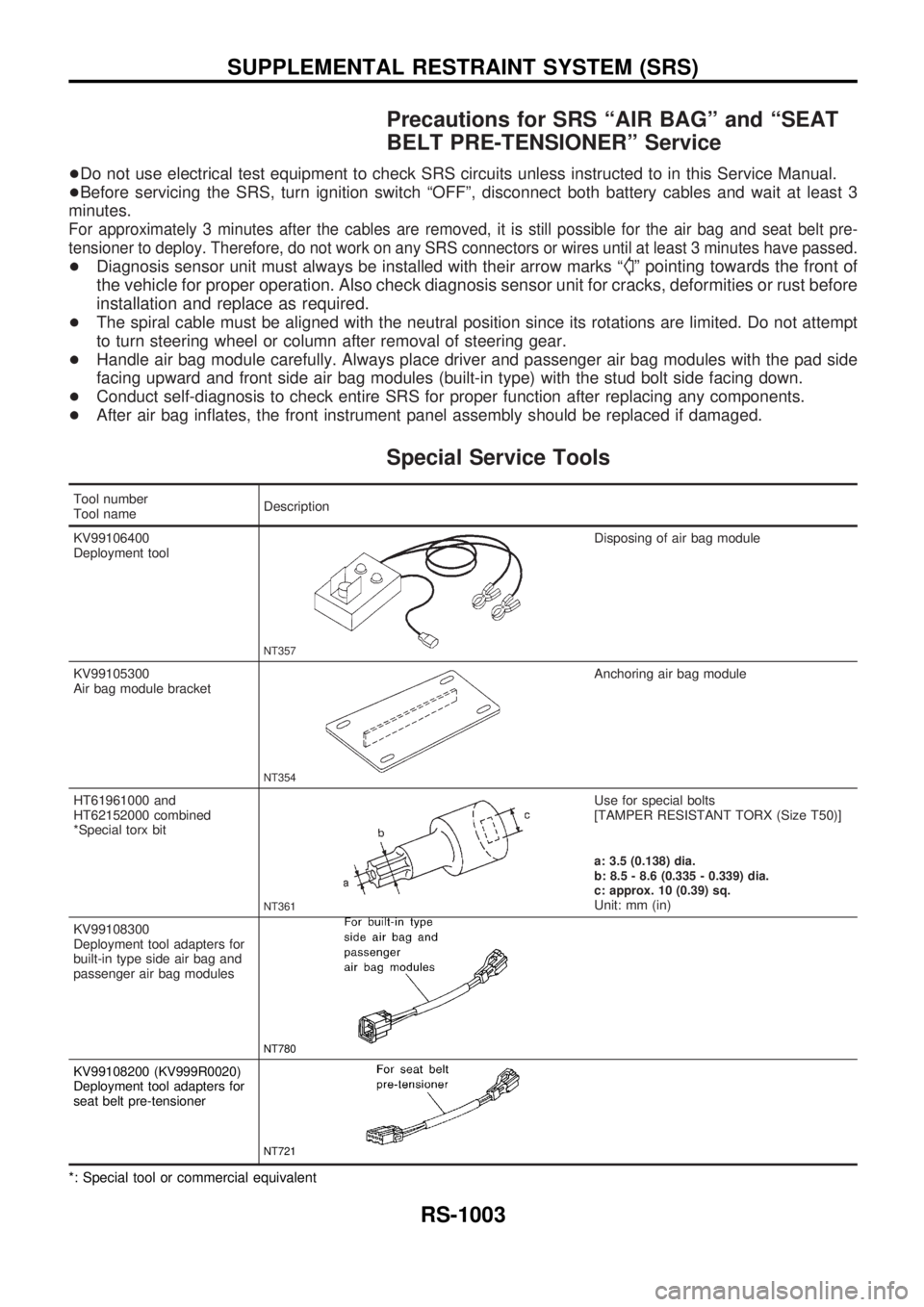
Special Service Tools
Tool number
Tool nameDescription
KV99106400
Deployment tool
NT357
Disposing of air bag module
KV99105300
Air bag module bracket
NT354
Anchoring air bag module
HT61961000 and
HT62152000 combined
*Special torx bit
NT361
Use for special bolts
[TAMPER RESISTANT TORX (Size T50)]
a: 3.5 (0.138) dia.
b: 8.5 - 8.6 (0.335 - 0.339) dia.
c: approx. 10 (0.39) sq.
Unit: mm (in)
KV99108300
Deployment tool adapters for
built-in type side air bag and
passenger air bag modules
NT780
KV99108200 (KV999R0020)
Deployment tool adapters for
seat belt pre-tensioner
NT721
*: Special tool or commercial equivalent
SUPPLEMENTAL RESTRAINT SYSTEM (SRS)
RS-1003
Page 978 of 1033
Maintenance Items
CAUTION:
Do not use electrical test equipment to check SRS circuit.
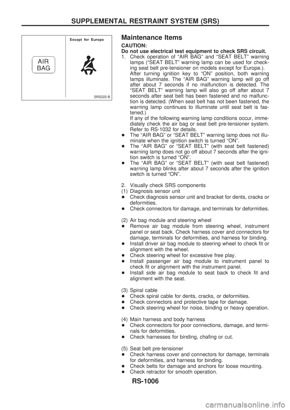
1. Check operation of ªAIR BAGº and ªSEAT BELTº warning
lamps (ªSEAT BELTº warning lamp can be used for check-
ing seat belt pre-tensioner on models except for Europe.).
After turning ignition key to ªONº position, both warning
lamps illuminate. The ªAIR BAGº warning lamp will go off
after about 7 seconds if no malfunction is detected. The
ªSEAT BELTº warning lamp will also go off after about 7
seconds after seat belt has been fastened and no malfunc-
tion is detected. (When seat belt has not been fastened, the
warning lamp continues to illuminate until seat belt is fas-
tened.)
If any of the following warning lamp conditions occur, imme-
diately check the air bag or seat belt pre-tensioner system.
Refer to RS-1032 for details.
+The ªAIR BAGº or ªSEAT BELTº warning lamp does not illu-
minate when the ignition switch is turned ªONº.
+The ªAIR BAGº or ªSEAT BELTº (with seat belt fastened)
warning lamp does not go off about 7 seconds after the igni-
tion switch is turned ªONº.
+The ªAIR BAGº or ªSEAT BELTº (with seat belt fastened)
warning lamp blinks after about 7 seconds after the ignition
switch is turned ªONº.
2. Visually check SRS components
(1) Diagnosis sensor unit
+Check diagnosis sensor unit and bracket for dents, cracks or
deformities.
+Check connectors for damage, and terminals for deformities.
(2) Air bag module and steering wheel
+Remove air bag module from steering wheel, instrument
panel or seat back. Check harness cover and connectors for
damage, terminals for deformities, and harness for binding.
+Install driver air bag module to steering wheel to check fit or
alignment with the wheel.
+Check steering wheel for excessive free play.
+Install passenger air bag module to instrument panel to
check fit or alignment with the instrument panel.
+Install side air bag module to seat back to check fit and
alignment with the seat.
(3) Spiral cable
+Check spiral cable for dents, cracks, or deformities.
+Check connectors and protective tape for damage.
+Check steering wheel for noise, binding or heavy operation.
(4) Main harness and body harness
+Check connectors for poor connections, damage, and termi-
nals for deformities.
+Check harnesses for binding, chafing or cut.
(5) Seat belt pre-tensioner
+Check harness cover and connectors for damage, terminals
for deformities, and harness for binding.
+Check belts for damage and anchors for loose mounting.
+Check retractor for smooth operation.
SRS222-B
SUPPLEMENTAL RESTRAINT SYSTEM (SRS)
RS-1006
Page 982 of 1033
CAUTION:
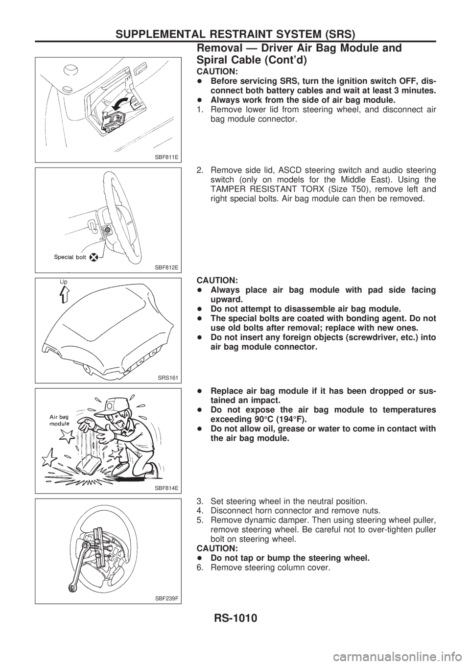
+Before servicing SRS, turn the ignition switch OFF, dis-
connect both battery cables and wait at least 3 minutes.
+Always work from the side of air bag module.
1. Remove lower lid from steering wheel, and disconnect air
bag module connector.
2. Remove side lid, ASCD steering switch and audio steering
switch (only on models for the Middle East). Using the
TAMPER RESISTANT TORX (Size T50), remove left and
right special bolts. Air bag module can then be removed.
CAUTION:
+Always place air bag module with pad side facing
upward.
+Do not attempt to disassemble air bag module.
+The special bolts are coated with bonding agent. Do not
use old bolts after removal; replace with new ones.
+Do not insert any foreign objects (screwdriver, etc.) into
air bag module connector.
+Replace air bag module if it has been dropped or sus-
tained an impact.
+Do not expose the air bag module to temperatures
exceeding 90ÉC (194ÉF).
+Do not allow oil, grease or water to come in contact with
the air bag module.
3. Set steering wheel in the neutral position.
4. Disconnect horn connector and remove nuts.
5. Remove dynamic damper. Then using steering wheel puller,
remove steering wheel. Be careful not to over-tighten puller
bolt on steering wheel.
CAUTION:
+Do not tap or bump the steering wheel.
6. Remove steering column cover.
SBF811E
SBF812E
SRS161
SBF814E
SBF239F
SUPPLEMENTAL RESTRAINT SYSTEM (SRS)
Removal Ð Driver Air Bag Module and
Spiral Cable (Cont'd)
RS-1010
Page 983 of 1033
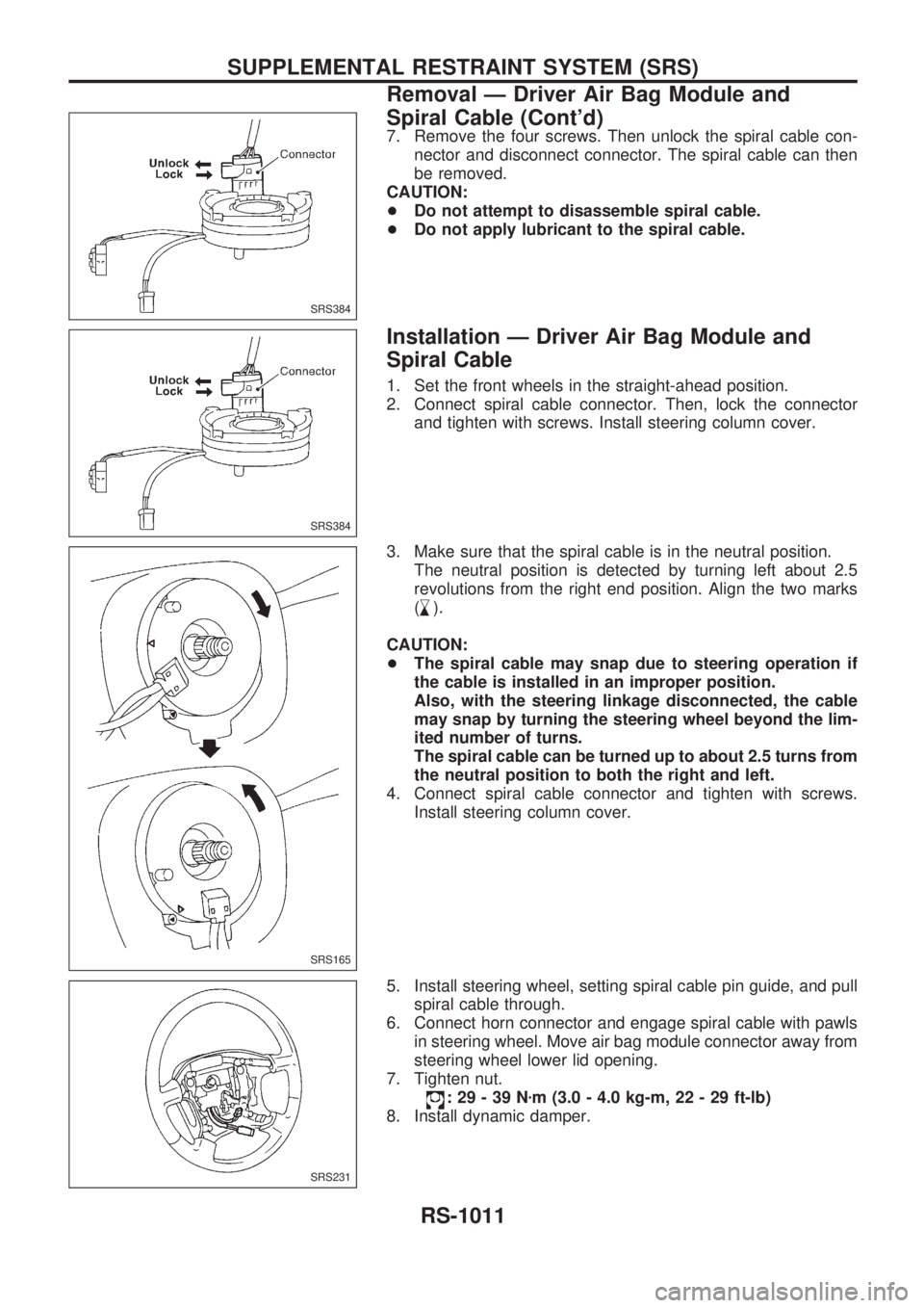
7. Remove the four screws. Then unlock the spiral cable con-
nector and disconnect connector. The spiral cable can then
be removed.
CAUTION:
+Do not attempt to disassemble spiral cable.
+Do not apply lubricant to the spiral cable.
Installation Ð Driver Air Bag Module and
Spiral Cable
1. Set the front wheels in the straight-ahead position.
2. Connect spiral cable connector. Then, lock the connector
and tighten with screws. Install steering column cover.
3. Make sure that the spiral cable is in the neutral position.
The neutral position is detected by turning left about 2.5
revolutions from the right end position. Align the two marks
(
,
m).
CAUTION:
+The spiral cable may snap due to steering operation if
the cable is installed in an improper position.
Also, with the steering linkage disconnected, the cable
may snap by turning the steering wheel beyond the lim-
ited number of turns.
The spiral cable can be turned up to about 2.5 turns from
the neutral position to both the right and left.
4. Connect spiral cable connector and tighten with screws.
Install steering column cover.
5. Install steering wheel, setting spiral cable pin guide, and pull
spiral cable through.
6. Connect horn connector and engage spiral cable with pawls
in steering wheel. Move air bag module connector away from
steering wheel lower lid opening.
7. Tighten nut.
:29-39Nzm (3.0 - 4.0 kg-m, 22 - 29 ft-lb)
8. Install dynamic damper.
SRS384
SRS384
SRS165
SRS231
SUPPLEMENTAL RESTRAINT SYSTEM (SRS)
Removal Ð Driver Air Bag Module and
Spiral Cable (Cont'd)
RS-1011