2000 NISSAN PATROL Harness
[x] Cancel search: HarnessPage 95 of 1033
VA
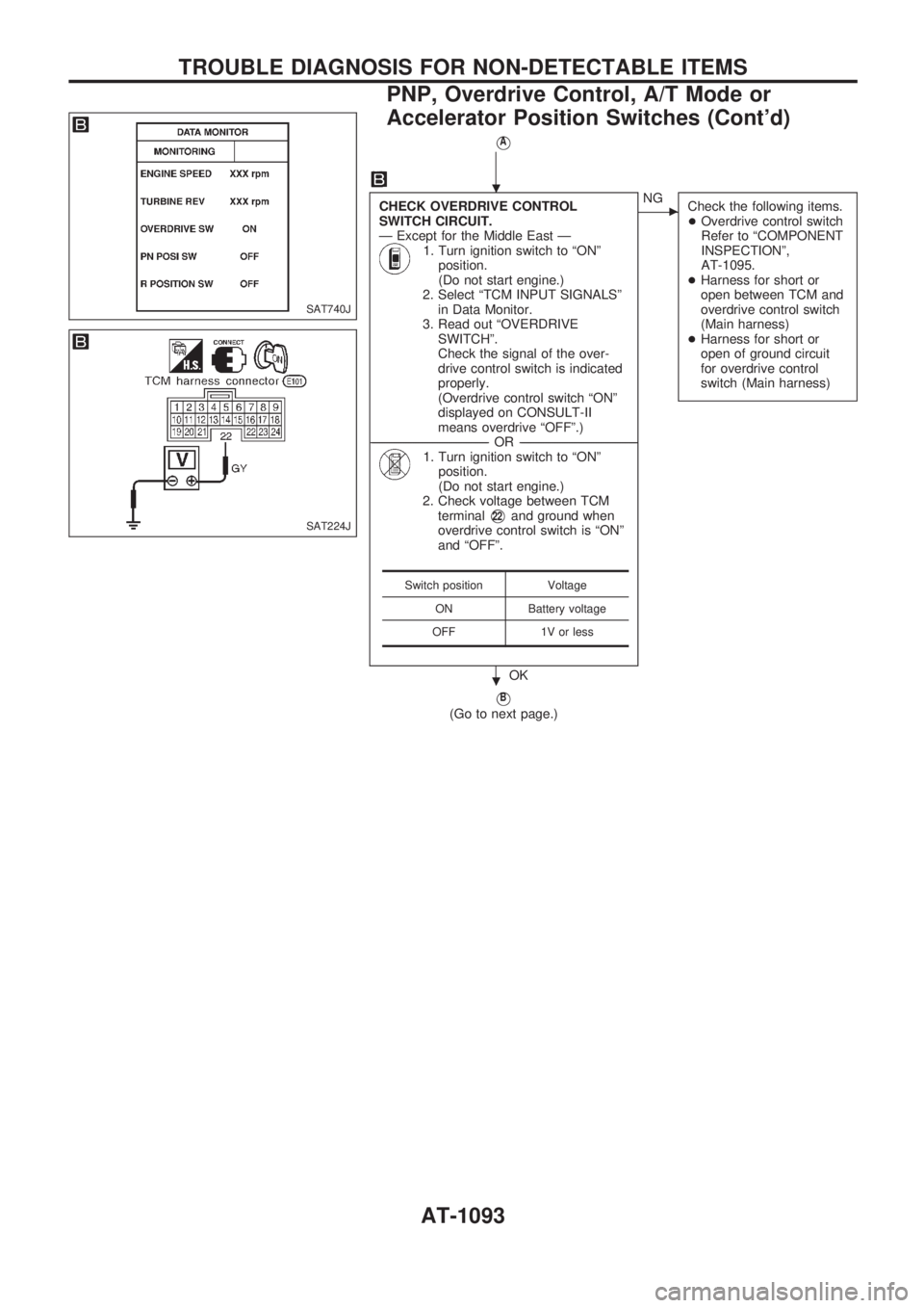
CHECK OVERDRIVE CONTROL
SWITCH CIRCUIT.
Ð Except for the Middle East Ð
1. Turn ignition switch to ªONº
position.
(Do not start engine.)
2. Select ªTCM INPUT SIGNALSº
in Data Monitor.
3. Read out ªOVERDRIVE
SWITCHº.
Check the signal of the over-
drive control switch is indicated
properly.
(Overdrive control switch ªONº
displayed on CONSULT-II
means overdrive ªOFFº.)
------------------------------------------------------------------------------------------------------------------------------------OR------------------------------------------------------------------------------------------------------------------------------------
1. Turn ignition switch to ªONº
position.
(Do not start engine.)
2. Check voltage between TCM
terminal
V22and ground when
overdrive control switch is ªONº
and ªOFFº.
OK
cNG
Check the following items.
+Overdrive control switch
Refer to ªCOMPONENT
INSPECTIONº,
AT-1095.
+Harness for short or
open between TCM and
overdrive control switch
(Main harness)
+Harness for short or
open of ground circuit
for overdrive control
switch (Main harness)
VB
(Go to next page.)
Switch position Voltage
ON Battery voltage
OFF 1V or less
SAT740J
SAT224J
.
.
TROUBLE DIAGNOSIS FOR NON-DETECTABLE ITEMS
PNP, Overdrive Control, A/T Mode or
Accelerator Position Switches (Cont'd)
AT-1093
Page 96 of 1033
VB
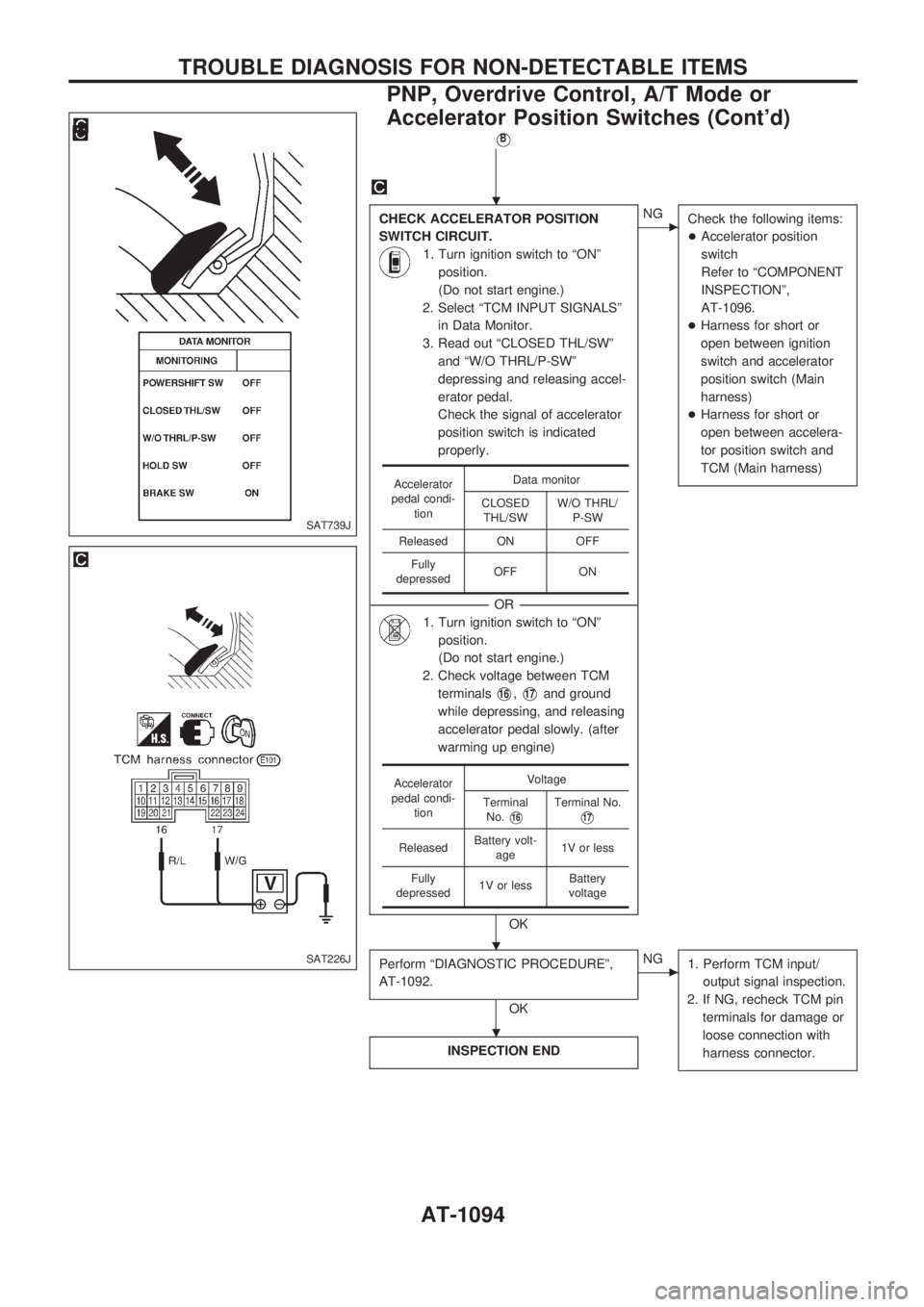
CHECK ACCELERATOR POSITION
SWITCH CIRCUIT.
1. Turn ignition switch to ªONº
position.
(Do not start engine.)
2. Select ªTCM INPUT SIGNALSº
in Data Monitor.
3. Read out ªCLOSED THL/SWº
and ªW/O THRL/P-SWº
depressing and releasing accel-
erator pedal.
Check the signal of accelerator
position switch is indicated
properly.
------------------------------------------------------------------------------------------------------------------------------------OR------------------------------------------------------------------------------------------------------------------------------------
1. Turn ignition switch to ªONº
position.
(Do not start engine.)
2. Check voltage between TCM
terminals
V16,V17and ground
while depressing, and releasing
accelerator pedal slowly. (after
warming up engine)
OK
cNG
Check the following items:
+Accelerator position
switch
Refer to ªCOMPONENT
INSPECTIONº,
AT-1096.
+Harness for short or
open between ignition
switch and accelerator
position switch (Main
harness)
+Harness for short or
open between accelera-
tor position switch and
TCM (Main harness)
Perform ªDIAGNOSTIC PROCEDUREº,
AT-1092.
OK
cNG
1. Perform TCM input/
output signal inspection.
2. If NG, recheck TCM pin
terminals for damage or
loose connection with
harness connector.
INSPECTION END
Accelerator
pedal condi-
tionData monitor
CLOSED
THL/SWW/O THRL/
P-SW
Released ON OFF
Fully
depressedOFF ON
Accelerator
pedal condi-
tionVoltage
Terminal
No.
V16Terminal No.
V17
ReleasedBattery volt-
age1V or less
Fully
depressed1V or lessBattery
voltage
SAT739J
SAT226J
.
.
.
TROUBLE DIAGNOSIS FOR NON-DETECTABLE ITEMS
PNP, Overdrive Control, A/T Mode or
Accelerator Position Switches (Cont'd)
AT-1094
Page 99 of 1033
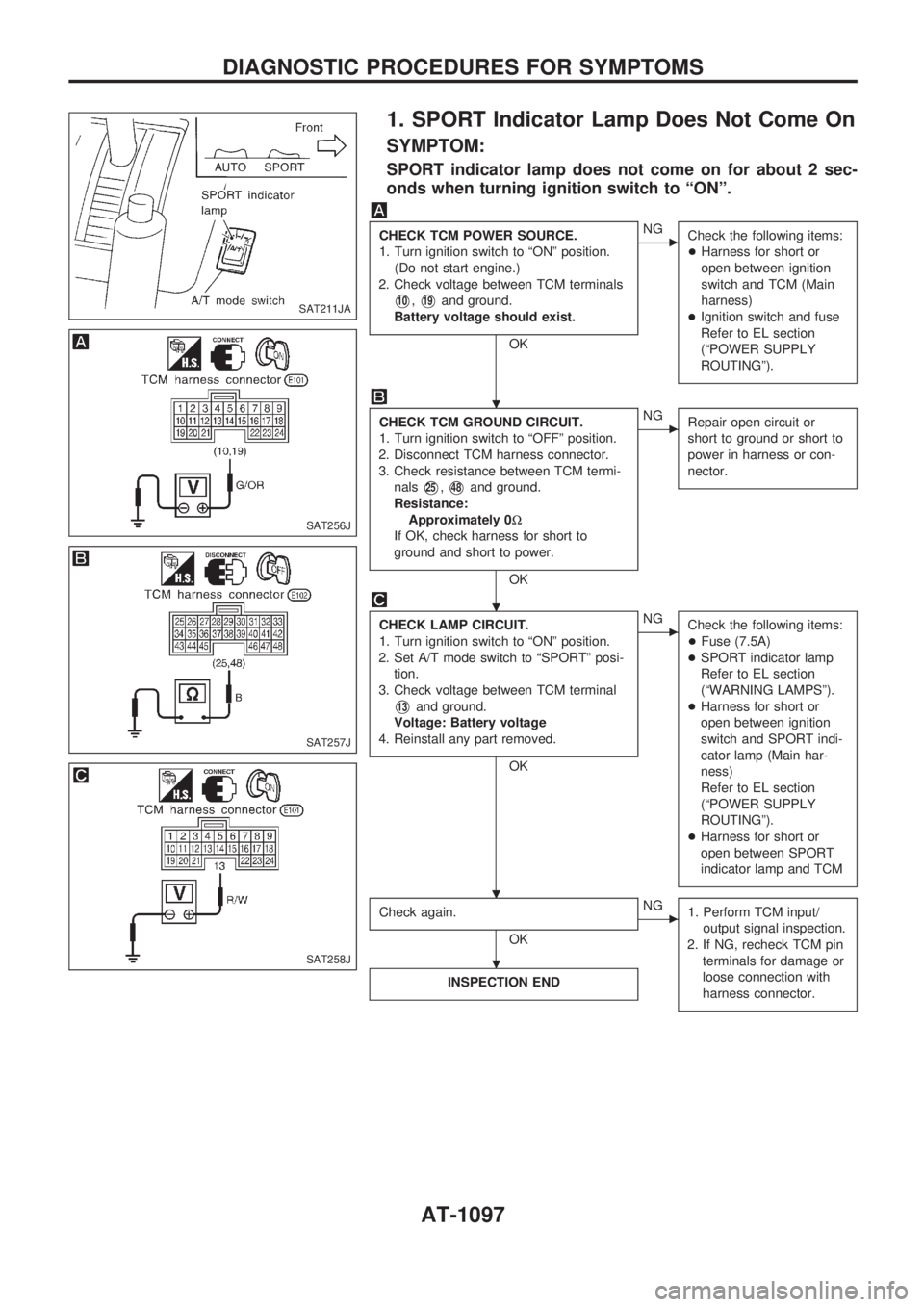
1. SPORT Indicator Lamp Does Not Come On
SYMPTOM:
SPORT indicator lamp does not come on for about 2 sec-
onds when turning ignition switch to ªONº.
CHECK TCM POWER SOURCE.
1. Turn ignition switch to ªONº position.
(Do not start engine.)
2. Check voltage between TCM terminals
V10,V19and ground.
Battery voltage should exist.
OK
cNG
Check the following items:
+Harness for short or
open between ignition
switch and TCM (Main
harness)
+Ignition switch and fuse
Refer to EL section
(ªPOWER SUPPLY
ROUTINGº).
CHECK TCM GROUND CIRCUIT.
1. Turn ignition switch to ªOFFº position.
2. Disconnect TCM harness connector.
3. Check resistance between TCM termi-
nals
V25,V48and ground.
Resistance:
Approximately 0W
If OK, check harness for short to
ground and short to power.
OK
cNG
Repair open circuit or
short to ground or short to
power in harness or con-
nector.
CHECK LAMP CIRCUIT.
1. Turn ignition switch to ªONº position.
2. Set A/T mode switch to ªSPORTº posi-
tion.
3. Check voltage between TCM terminal
V13and ground.
Voltage: Battery voltage
4. Reinstall any part removed.
OK
cNG
Check the following items:
+Fuse (7.5A)
+SPORT indicator lamp
Refer to EL section
(ªWARNING LAMPSº).
+Harness for short or
open between ignition
switch and SPORT indi-
cator lamp (Main har-
ness)
Refer to EL section
(ªPOWER SUPPLY
ROUTINGº).
+Harness for short or
open between SPORT
indicator lamp and TCM
Check again.
OK
cNG
1. Perform TCM input/
output signal inspection.
2. If NG, recheck TCM pin
terminals for damage or
loose connection with
harness connector.
INSPECTION END
SAT211JA
SAT256J
SAT257J
SAT258J
.
.
. .
.
DIAGNOSTIC PROCEDURES FOR SYMPTOMS
AT-1097
Page 100 of 1033
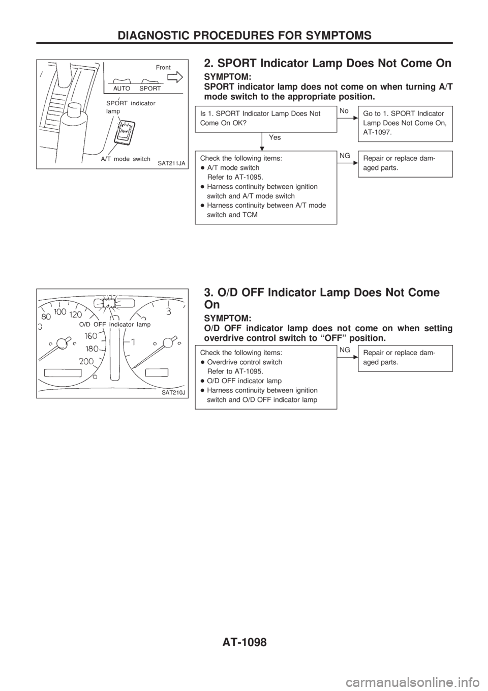
2. SPORT Indicator Lamp Does Not Come On
SYMPTOM:
SPORT indicator lamp does not come on when turning A/T
mode switch to the appropriate position.
Is 1. SPORT Indicator Lamp Does Not
Come On OK?
Yes
cNo
Go to 1. SPORT Indicator
Lamp Does Not Come On,
AT-1097.
Check the following items:
+A/T mode switch
Refer to AT-1095.
+Harness continuity between ignition
switch and A/T mode switch
+Harness continuity between A/T mode
switch and TCMcNG
Repair or replace dam-
aged parts.
3. O/D OFF Indicator Lamp Does Not Come
On
SYMPTOM:
O/D OFF indicator lamp does not come on when setting
overdrive control switch to ªOFFº position.
Check the following items:
+Overdrive control switch
Refer to AT-1095.
+O/D OFF indicator lamp
+Harness continuity between ignition
switch and O/D OFF indicator lampcNG
Repair or replace dam-
aged parts.
SAT211JA
SAT210J
.
DIAGNOSTIC PROCEDURES FOR SYMPTOMS
AT-1098
Page 103 of 1033
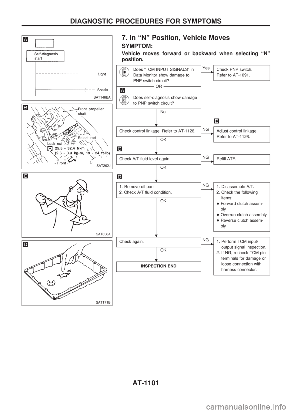
7. In ªNº Position, Vehicle Moves
SYMPTOM:
Vehicle moves forward or backward when selecting ªNº
position.
Does ªTCM INPUT SIGNALSº in
Data Monitor show damage to
PNP switch circuit?
------------------------------------------------------------------------------------------------------------------------------------OR------------------------------------------------------------------------------------------------------------------------------------
Does self-diagnosis show damage
to PNP switch circuit?
No
cYes
Check PNP switch.
Refer to AT-1091.
Check control linkage. Refer to AT-1126.
OK
cNG
Adjust control linkage.
Refer to AT-1126.
Check A/T fluid level again.
OK
cNG
Refill ATF.
1. Remove oil pan.
2. Check A/T fluid condition.
OK
cNG
1. Disassemble A/T.
2. Check the following
items:
+Forward clutch assem-
bly
+Overrun clutch assembly
+Reverse clutch assem-
bly
Check again.
OK
cNG
1. Perform TCM input/
output signal inspection.
2. If NG, recheck TCM pin
terminals for damage or
loose connection with
harness connector.
INSPECTION END
SAT146BA
SAT262J
SAT638A
SAT171B
.
.
.
. .
.
DIAGNOSTIC PROCEDURES FOR SYMPTOMS
AT-1101
Page 104 of 1033
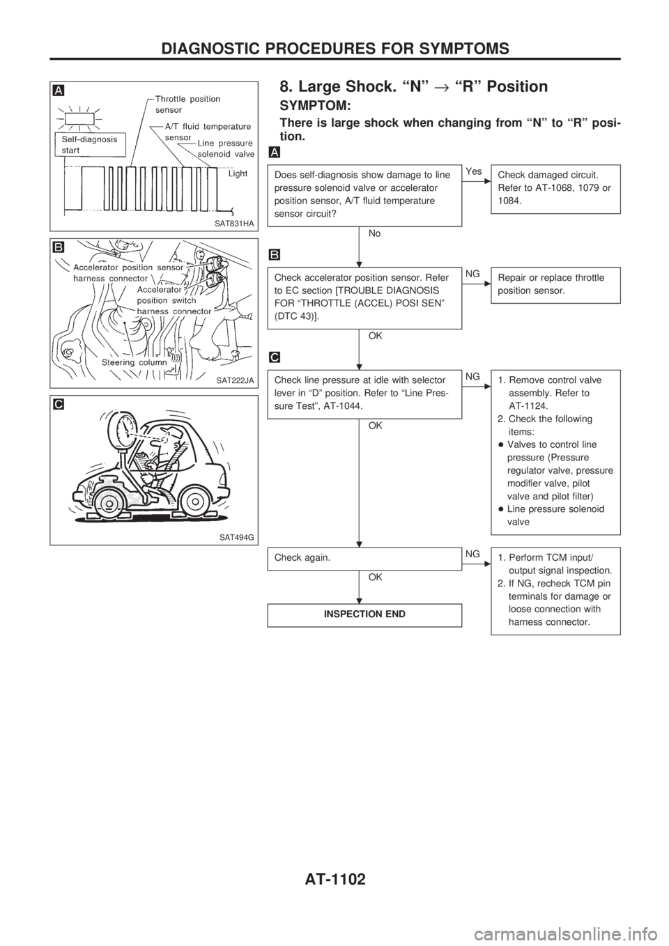
8. Large Shock. ªNº®ªRº Position
SYMPTOM:
There is large shock when changing from ªNº to ªRº posi-
tion.
Does self-diagnosis show damage to line
pressure solenoid valve or accelerator
position sensor, A/T fluid temperature
sensor circuit?
No
cYes
Check damaged circuit.
Refer to AT-1068, 1079 or
1084.
Check accelerator position sensor. Refer
to EC section [TROUBLE DIAGNOSIS
FOR ªTHROTTLE (ACCEL) POSI SENº
(DTC 43)].
OK
cNG
Repair or replace throttle
position sensor.
Check line pressure at idle with selector
lever in ªDº position. Refer to ªLine Pres-
sure Testº, AT-1044.
OK
cNG
1. Remove control valve
assembly. Refer to
AT-1124.
2. Check the following
items:
+Valves to control line
pressure (Pressure
regulator valve, pressure
modifier valve, pilot
valve and pilot filter)
+Line pressure solenoid
valve
Check again.
OK
cNG
1. Perform TCM input/
output signal inspection.
2. If NG, recheck TCM pin
terminals for damage or
loose connection with
harness connector.
INSPECTION END
SAT831HA
SAT222JA
SAT494G
.
.
. .
.
DIAGNOSTIC PROCEDURES FOR SYMPTOMS
AT-1102
Page 105 of 1033
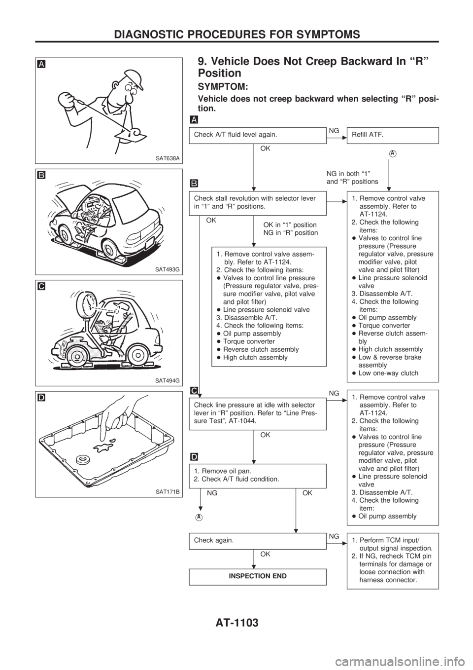
9. Vehicle Does Not Creep Backward In ªRº
Position
SYMPTOM:
Vehicle does not creep backward when selecting ªRº posi-
tion.
Check A/T fluid level again.
OK
cNG
Refill ATF.
VA
NG in both ª1º
and ªRº positions
Check stall revolution with selector lever
in ª1º and ªRº positions.
OK
OK in ª1º position
NG in ªRº position
c1. Remove control valve
assembly. Refer to
AT-1124.
2. Check the following
items:
+Valves to control line
pressure (Pressure
regulator valve, pressure
modifier valve, pilot
valve and pilot filter)
+Line pressure solenoid
valve
3. Disassemble A/T.
4. Check the following
items:
+Oil pump assembly
+Torque converter
+Reverse clutch assem-
bly
+High clutch assembly
+Low & reverse brake
assembly
+Low one-way clutch
1. Remove control valve assem-
bly. Refer to AT-1124.
2. Check the following items:
+Valves to control line pressure
(Pressure regulator valve, pres-
sure modifier valve, pilot valve
and pilot filter)
+Line pressure solenoid valve
3. Disassemble A/T.
4. Check the following items:
+Oil pump assembly
+Torque converter
+Reverse clutch assembly
+High clutch assembly
Check line pressure at idle with selector
lever in ªRº position. Refer to ªLine Pres-
sure Testº, AT-1044.
OK
cNG
1. Remove control valve
assembly. Refer to
AT-1124.
2. Check the following
items:
+Valves to control line
pressure (Pressure
regulator valve, pressure
modifier valve, pilot
valve and pilot filter)
+Line pressure solenoid
valve
3. Disassemble A/T.
4. Check the following
item:
+Oil pump assembly
1. Remove oil pan.
2. Check A/T fluid condition.
NG OK
VA
Check again.
OK
cNG
1. Perform TCM input/
output signal inspection.
2. If NG, recheck TCM pin
terminals for damage or
loose connection with
harness connector.
INSPECTION END
SAT638A
SAT493G
SAT494G
SAT171B
..
.
.
.
.
.
.
DIAGNOSTIC PROCEDURES FOR SYMPTOMS
AT-1103
Page 107 of 1033
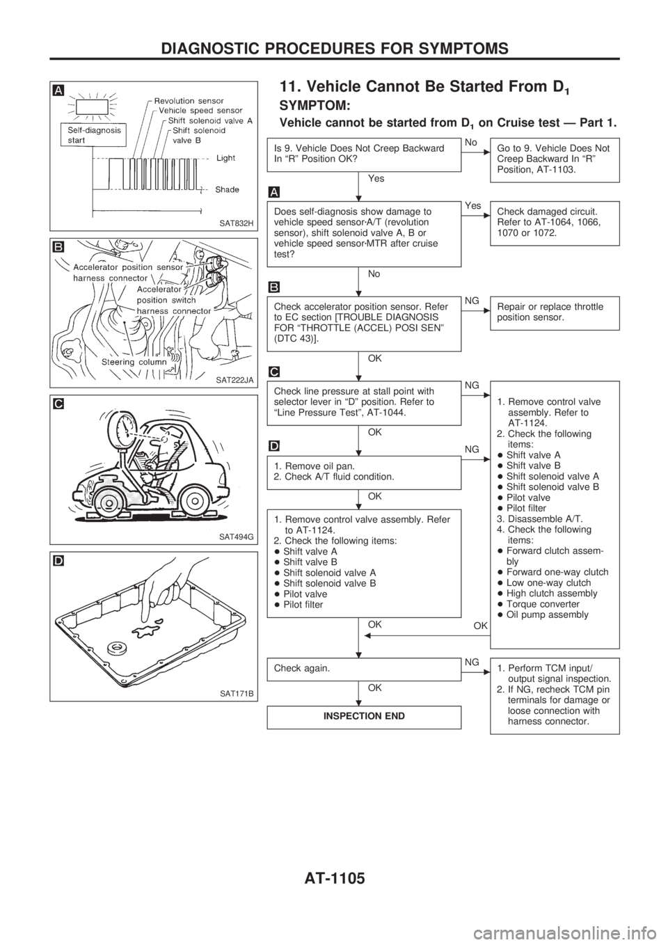
11. Vehicle Cannot Be Started From D1
SYMPTOM:
Vehicle cannot be started from D1on Cruise test Ð Part 1.
Is 9. Vehicle Does Not Creep Backward
In ªRº Position OK?
Yes
cNo
Go to 9. Vehicle Does Not
Creep Backward In ªRº
Position, AT-1103.
Does self-diagnosis show damage to
vehicle speed sensorzA/T (revolution
sensor), shift solenoid valve A, B or
vehicle speed sensorzMTR after cruise
test?
No
cYes
Check damaged circuit.
Refer to AT-1064, 1066,
1070 or 1072.
Check accelerator position sensor. Refer
to EC section [TROUBLE DIAGNOSIS
FOR ªTHROTTLE (ACCEL) POSI SENº
(DTC 43)].
OK
cNG
Repair or replace throttle
position sensor.
Check line pressure at stall point with
selector lever in ªDº position. Refer to
ªLine Pressure Testº, AT-1044.
OK
cNG
1. Remove control valve
assembly. Refer to
AT-1124.
2. Check the following
items:
+Shift valve A
+Shift valve B
+Shift solenoid valve A
+Shift solenoid valve B
+Pilot valve
+Pilot filter
3. Disassemble A/T.
4. Check the following
items:
+Forward clutch assem-
bly
+Forward one-way clutch
+Low one-way clutch
+High clutch assembly
+Torque converter
+Oil pump assembly
1. Remove oil pan.
2. Check A/T fluid condition.
OK
cNG
1. Remove control valve assembly. Refer
to AT-1124.
2. Check the following items:
+Shift valve A
+Shift valve B
+Shift solenoid valve A
+Shift solenoid valve B
+Pilot valve
+Pilot filter
OK
OKb
Check again.
OK
cNG
1. Perform TCM input/
output signal inspection.
2. If NG, recheck TCM pin
terminals for damage or
loose connection with
harness connector.
INSPECTION END
SAT832H
SAT222JA
SAT494G
SAT171B
.
.
.
.
.
. .
.
DIAGNOSTIC PROCEDURES FOR SYMPTOMS
AT-1105