2000 NISSAN PATROL turn signal
[x] Cancel search: turn signalPage 666 of 1033
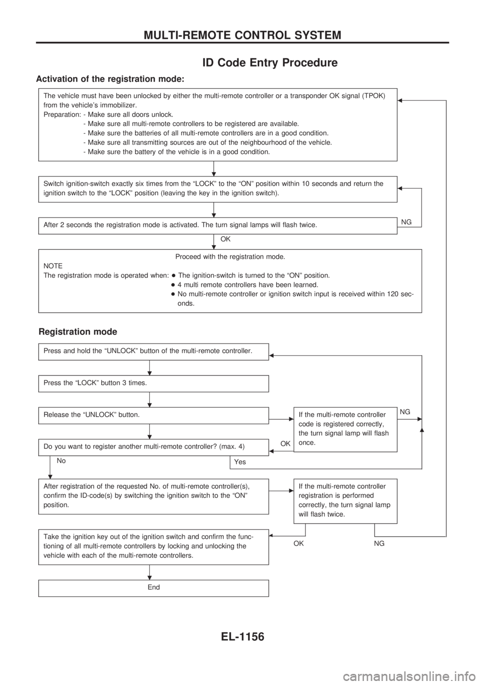
ID Code Entry Procedure
Activation of the registration mode:
The vehicle must have been unlocked by either the multi-remote controller or a transponder OK signal (TPOK)
from the vehicle's immobilizer.
Preparation: - Make sure all doors unlock.
- Make sure all multi-remote controllers to be registered are available.
- Make sure the batteries of all multi-remote controllers are in a good condition.
- Make sure all transmitting sources are out of the neighbourhood of the vehicle.
- Make sure the battery of the vehicle is in a good condition.b
Switch ignition-switch exactly six times from the ªLOCKº to the ªONº position within 10 seconds and return the
ignition switch to the ªLOCKº position (leaving the key in the ignition switch).b
After 2 seconds the registration mode is activated. The turn signal lamps will flash twice.
OKNG
Proceed with the registration mode.
NOTE
The registration mode is operated when:+The ignition-switch is turned to the ªONº position.
+4 multi remote controllers have been learned.
+No multi-remote controller or ignition switch input is received within 120 sec-
onds.
Registration mode
Press and hold the ªUNLOCKº button of the multi-remote controller.b
Press the ªLOCKº button 3 times.
Release the ªUNLOCKº button.cIf the multi-remote controller
code is registered correctly,
the turn signal lamp will flash
once.cNG
Do you want to register another multi-remote controller? (max. 4)
No
Yes
bOK
m
After registration of the requested No. of multi-remote controller(s),
confirm the ID-code(s) by switching the ignition switch to the ªONº
position.cIf the multi-remote controller
registration is performed
correctly, the turn signal lamp
will flash twice.
Take the ignition key out of the ignition switch and confirm the func-
tioning of all multi-remote controllers by locking and unlocking the
vehicle with each of the multi-remote controllers.b
OKNG
End
.
.
.
.
.
.
.
.
MULTI-REMOTE CONTROL SYSTEM
EL-1156
Page 672 of 1033
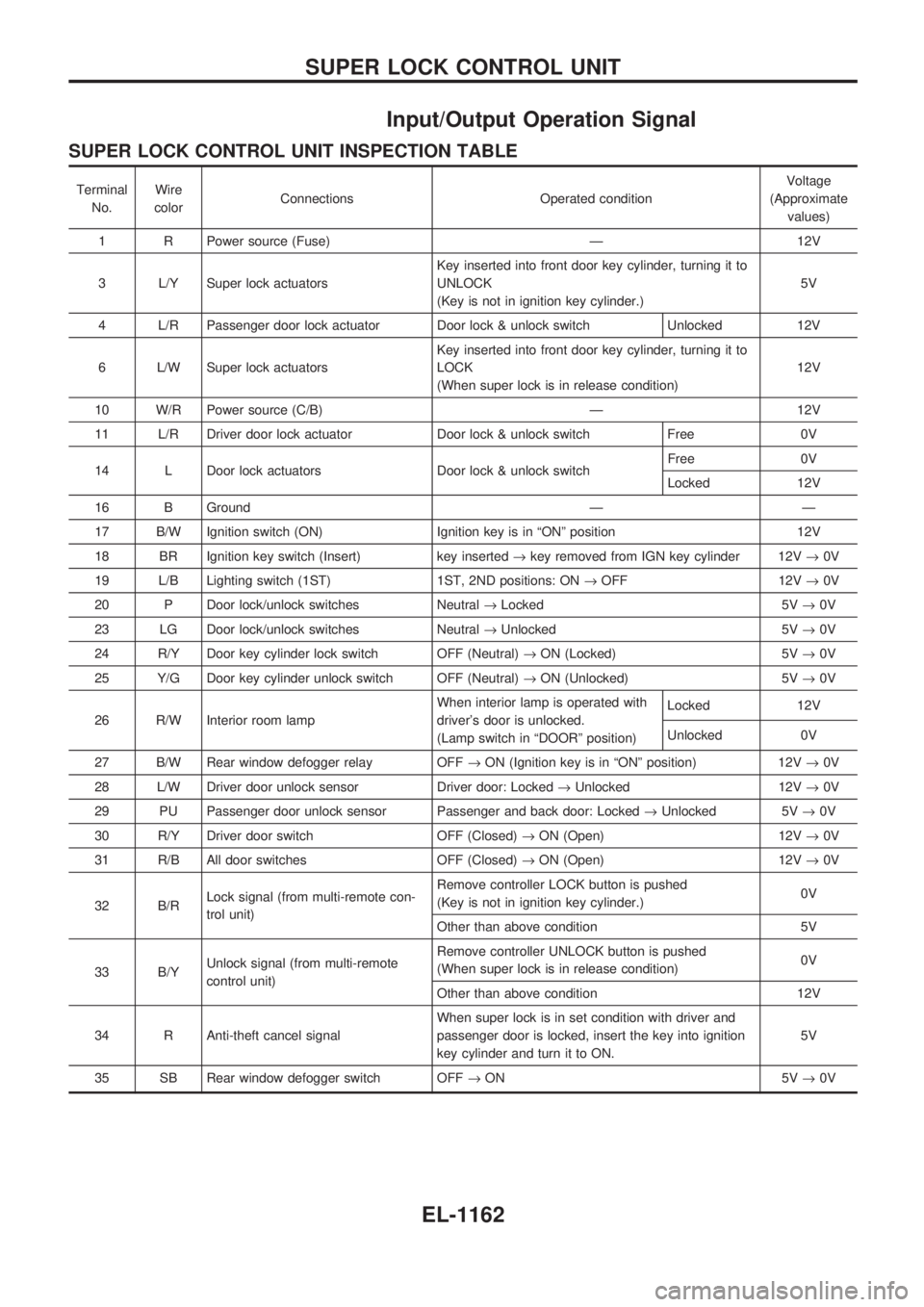
Input/Output Operation Signal
SUPER LOCK CONTROL UNIT INSPECTION TABLE
Terminal
No.Wire
colorConnections Operated conditionVoltage
(Approximate
values)
1 R Power source (Fuse) Ð 12V
3 L/Y Super lock actuatorsKey inserted into front door key cylinder, turning it to
UNLOCK
(Key is not in ignition key cylinder.)5V
4 L/R Passenger door lock actuator Door lock & unlock switch Unlocked 12V
6 L/W Super lock actuatorsKey inserted into front door key cylinder, turning it to
LOCK
(When super lock is in release condition)12V
10 W/R Power source (C/B) Ð 12V
11 L/R Driver door lock actuator Door lock & unlock switch Free 0V
14 L Door lock actuators Door lock & unlock switchFree 0V
Locked 12V
16 B Ground Ð Ð
17 B/W Ignition switch (ON) Ignition key is in ªONº position 12V
18 BR Ignition key switch (Insert) key inserted®key removed from IGN key cylinder 12V®0V
19 L/B Lighting switch (1ST) 1ST, 2ND positions: ON®OFF 12V®0V
20 P Door lock/unlock switches Neutral®Locked 5V®0V
23 LG Door lock/unlock switches Neutral®Unlocked 5V®0V
24 R/Y Door key cylinder lock switch OFF (Neutral)®ON (Locked) 5V®0V
25 Y/G Door key cylinder unlock switch OFF (Neutral)®ON (Unlocked) 5V®0V
26 R/W Interior room lampWhen interior lamp is operated with
driver's door is unlocked.
(Lamp switch in ªDOORº position)Locked 12V
Unlocked 0V
27 B/W Rear window defogger relay OFF®ON (Ignition key is in ªONº position) 12V®0V
28 L/W Driver door unlock sensor Driver door: Locked®Unlocked 12V®0V
29 PU Passenger door unlock sensor Passenger and back door: Locked®Unlocked 5V®0V
30 R/Y Driver door switch OFF (Closed)®ON (Open) 12V®0V
31 R/B All door switches OFF (Closed)®ON (Open) 12V®0V
32 B/RLock signal (from multi-remote con-
trol unit)Remove controller LOCK button is pushed
(Key is not in ignition key cylinder.)0V
Other than above condition 5V
33 B/YUnlock signal (from multi-remote
control unit)Remove controller UNLOCK button is pushed
(When super lock is in release condition)0V
Other than above condition 12V
34 R Anti-theft cancel signalWhen super lock is in set condition with driver and
passenger door is locked, insert the key into ignition
key cylinder and turn it to ON.5V
35 SB Rear window defogger switch OFF®ON 5V®0V
SUPER LOCK CONTROL UNIT
EL-1162
Page 687 of 1033
VA
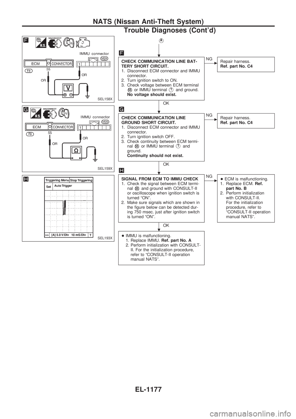
CHECK COMMUNICATION LINE BAT-
TERY SHORT CIRCUIT.
1. Disconnect ECM connector and IMMU
connector.
2. Turn ignition switch to ON.
3. Check voltage between ECM terminal
V55or IMMU terminalV1and ground.
No voltage should exist.
OK
cNG
Repair harness.
Ref. part No. C4
CHECK COMMUNICATION LINE
GROUND SHORT CIRCUIT.
1. Disconnect ECM connector and IMMU
connector.
2. Turn ignition switch OFF.
3. Check continuity between ECM termi-
nal
V55or IMMU terminalV1and
ground.
Continuity should not exist.
OK
cNG
Repair harness.
Ref. part No. C4
SIGNAL FROM ECM TO IMMU CHECK
1. Check the signal between ECM termi-
nal
V55and ground with CONSULT-II
or oscilloscope when ignition switch is
turned ªONº.
2. Make sure signals which are shown in
the figure below can be detected dur-
ing 750 msec. just after ignition switch
is turned ªONº.
OK
cNG
+ECM is malfunctioning.
1. Replace ECM.Ref.
part No. B
2. Perform initialization
with CONSULT-II.
For the initialization
procedure, refer to
ªCONSULT-II operation
manual NATSº.
+IMMU is malfunctioning.
1. Replace IMMU.Ref. part No. A
2. Perform initialization with CONSULT-
II. For the initialization procedure,
refer to ªCONSULT-II operation
manual NATSº.
SEL158X
SEL159X
SEL193X
.
.
.
.
NATS (Nissan Anti-Theft System)
Trouble Diagnoses (Cont'd)
EL-1177
Page 737 of 1033
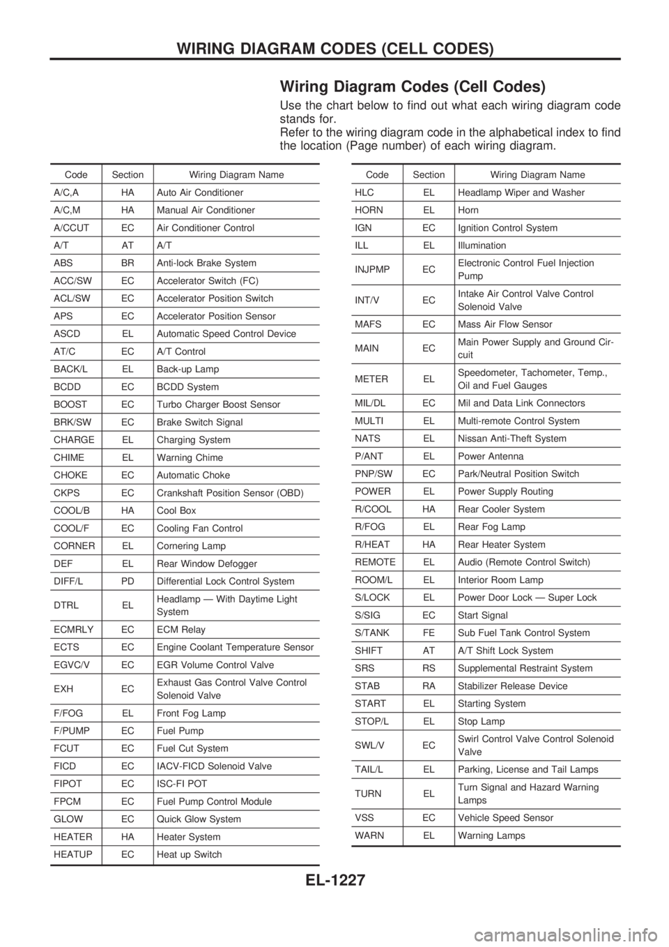
Wiring Diagram Codes (Cell Codes)
Use the chart below to find out what each wiring diagram code
stands for.
Refer to the wiring diagram code in the alphabetical index to find
the location (Page number) of each wiring diagram.
Code Section Wiring Diagram Name
A/C,A HA Auto Air Conditioner
A/C,M HA Manual Air Conditioner
A/CCUT EC Air Conditioner Control
A/T AT A/T
ABS BR Anti-lock Brake System
ACC/SW EC Accelerator Switch (FC)
ACL/SW EC Accelerator Position Switch
APS EC Accelerator Position Sensor
ASCD EL Automatic Speed Control Device
AT/C EC A/T Control
BACK/L EL Back-up Lamp
BCDD EC BCDD System
BOOST EC Turbo Charger Boost Sensor
BRK/SW EC Brake Switch Signal
CHARGE EL Charging System
CHIME EL Warning Chime
CHOKE EC Automatic Choke
CKPS EC Crankshaft Position Sensor (OBD)
COOL/B HA Cool Box
COOL/F EC Cooling Fan Control
CORNER EL Cornering Lamp
DEF EL Rear Window Defogger
DIFF/L PD Differential Lock Control System
DTRL ELHeadlamp Ð With Daytime Light
System
ECMRLY EC ECM Relay
ECTS EC Engine Coolant Temperature Sensor
EGVC/V EC EGR Volume Control Valve
EXH ECExhaust Gas Control Valve Control
Solenoid Valve
F/FOG EL Front Fog Lamp
F/PUMP EC Fuel Pump
FCUT EC Fuel Cut System
FICD EC IACV-FICD Solenoid Valve
FIPOT EC ISC-FI POT
FPCM EC Fuel Pump Control Module
GLOW EC Quick Glow System
HEATER HA Heater System
HEATUP EC Heat up SwitchCode Section Wiring Diagram Name
HLC EL Headlamp Wiper and Washer
HORN EL Horn
IGN EC Ignition Control System
ILL EL Illumination
INJPMP ECElectronic Control Fuel Injection
Pump
INT/V ECIntake Air Control Valve Control
Solenoid Valve
MAFS EC Mass Air Flow Sensor
MAIN ECMain Power Supply and Ground Cir-
cuit
METER ELSpeedometer, Tachometer, Temp.,
Oil and Fuel Gauges
MIL/DL EC Mil and Data Link Connectors
MULTI EL Multi-remote Control System
NATS EL Nissan Anti-Theft System
P/ANT EL Power Antenna
PNP/SW EC Park/Neutral Position Switch
POWER EL Power Supply Routing
R/COOL HA Rear Cooler System
R/FOG EL Rear Fog Lamp
R/HEAT HA Rear Heater System
REMOTE EL Audio (Remote Control Switch)
ROOM/L EL Interior Room Lamp
S/LOCK EL Power Door Lock Ð Super Lock
S/SIG EC Start Signal
S/TANK FE Sub Fuel Tank Control System
SHIFT AT A/T Shift Lock System
SRS RS Supplemental Restraint System
STAB RA Stabilizer Release Device
START EL Starting System
STOP/L EL Stop Lamp
SWL/V ECSwirl Control Valve Control Solenoid
Valve
TAIL/L EL Parking, License and Tail Lamps
TURN ELTurn Signal and Hazard Warning
Lamps
VSS EC Vehicle Speed Sensor
WARN EL Warning Lamps
WIRING DIAGRAM CODES (CELL CODES)
EL-1227
Page 883 of 1033
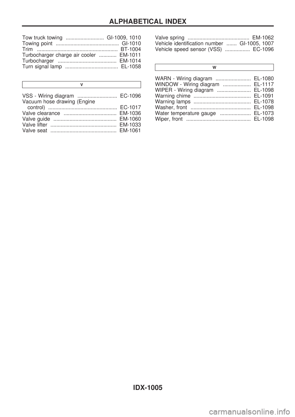
Tow truck towing .......................... GI-1009, 1010
Towing point ........................................... GI-1010
Trim ....................................................... BT-1004
Turbocharger charge air cooler ............ EM-1011
Turbocharger ........................................ EM-1014
Turn signal lamp .................................... EL-1058
V
VSS - Wiring diagram ........................... EC-1096
Vacuum hose drawing (Engine
control) ............................................... EC-1017
Valve clearance .................................... EM-1036
Valve guide ........................................... EM-1060
Valve lifter ............................................. EM-1033
Valve seat ............................................. EM-1061Valve spring .......................................... EM-1062
Vehicle identification number ....... GI-1005, 1007
Vehicle speed sensor (VSS) ................. EC-1096
W
WARN - Wiring diagram ........................ EL-1080
WINDOW - Wiring diagram ................... EL-1117
WIPER - Wiring diagram ....................... EL-1098
Warning chime ....................................... EL-1091
Warning lamps ....................................... EL-1078
Washer, front ......................................... EL-1098
Water temperature gauge ..................... EL-1073
Wiper, front ............................................ EL-1098
ALPHABETICAL INDEX
IDX-1005