2000 NISSAN PATROL turn signal
[x] Cancel search: turn signalPage 485 of 1033
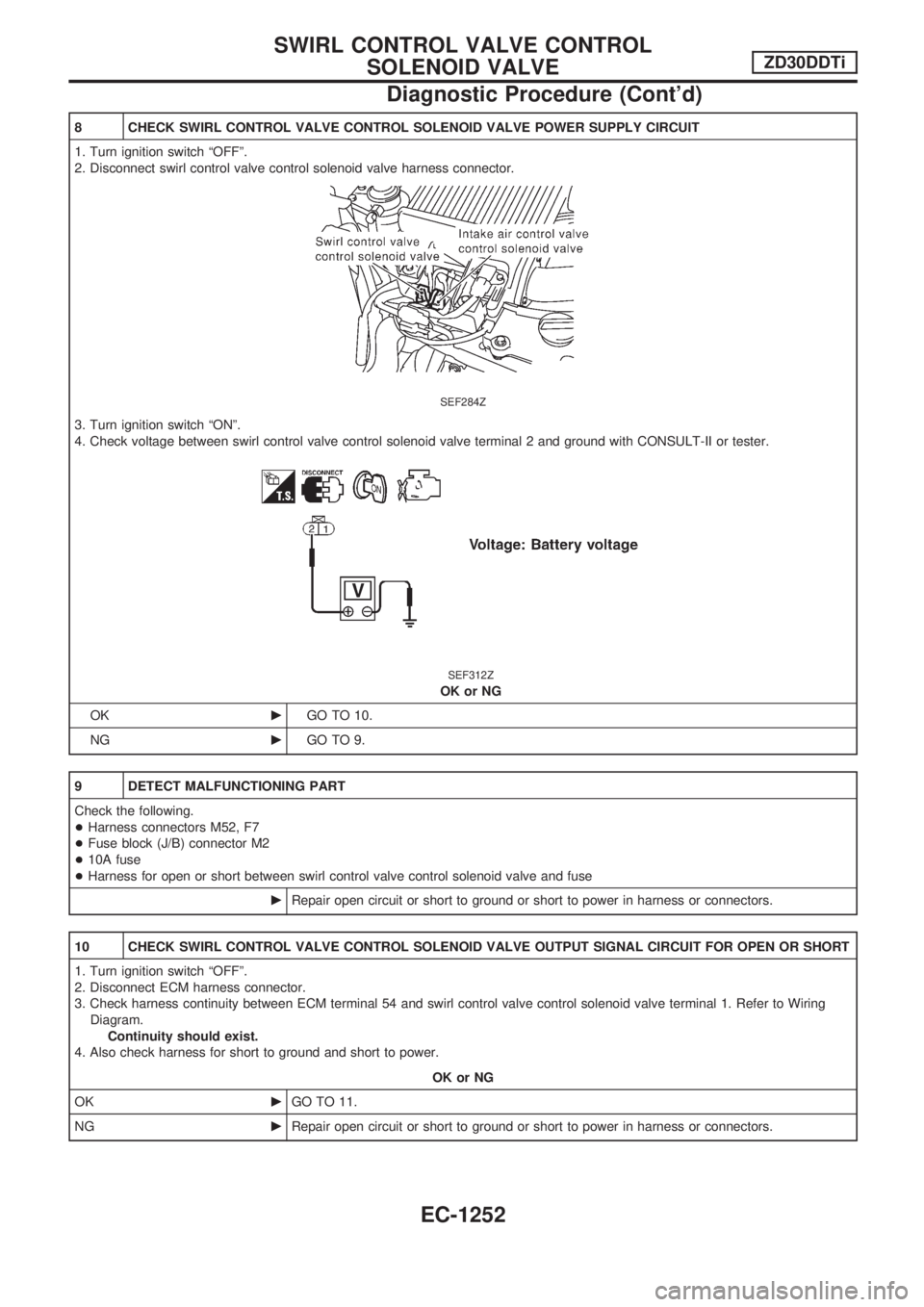
8 CHECK SWIRL CONTROL VALVE CONTROL SOLENOID VALVE POWER SUPPLY CIRCUIT
1. Turn ignition switch ªOFFº.
2. Disconnect swirl control valve control solenoid valve harness connector.
SEF284Z
3. Turn ignition switch ªONº.
4. Check voltage between swirl control valve control solenoid valve terminal 2 and ground with CONSULT-II or tester.
SEF312Z
OK or NG
OKcGO TO 10.
NGcGO TO 9.
9 DETECT MALFUNCTIONING PART
Check the following.
+Harness connectors M52, F7
+Fuse block (J/B) connector M2
+10A fuse
+Harness for open or short between swirl control valve control solenoid valve and fuse
cRepair open circuit or short to ground or short to power in harness or connectors.
10 CHECK SWIRL CONTROL VALVE CONTROL SOLENOID VALVE OUTPUT SIGNAL CIRCUIT FOR OPEN OR SHORT
1. Turn ignition switch ªOFFº.
2. Disconnect ECM harness connector.
3. Check harness continuity between ECM terminal 54 and swirl control valve control solenoid valve terminal 1. Refer to Wiring
Diagram.
Continuity should exist.
4. Also check harness for short to ground and short to power.
OK or NG
OKcGO TO 11.
NGcRepair open circuit or short to ground or short to power in harness or connectors.
SWIRL CONTROL VALVE CONTROL
SOLENOID VALVEZD30DDTi
Diagnostic Procedure (Cont'd)
EC-1252
Page 493 of 1033
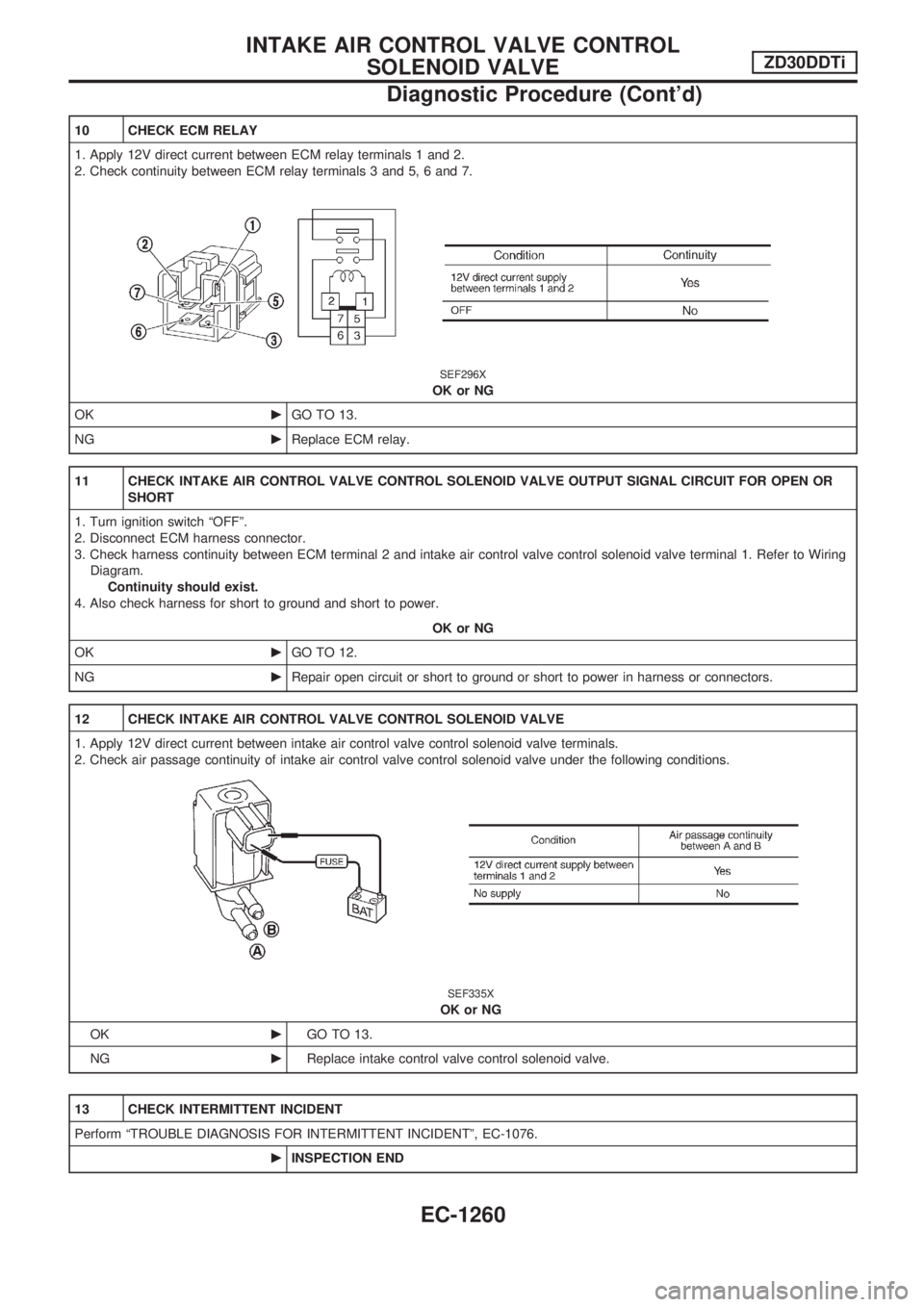
10 CHECK ECM RELAY
1. Apply 12V direct current between ECM relay terminals 1 and 2.
2. Check continuity between ECM relay terminals 3 and 5, 6 and 7.
SEF296X
OK or NG
OKcGO TO 13.
NGcReplace ECM relay.
11 CHECK INTAKE AIR CONTROL VALVE CONTROL SOLENOID VALVE OUTPUT SIGNAL CIRCUIT FOR OPEN OR
SHORT
1. Turn ignition switch ªOFFº.
2. Disconnect ECM harness connector.
3. Check harness continuity between ECM terminal 2 and intake air control valve control solenoid valve terminal 1. Refer to Wiring
Diagram.
Continuity should exist.
4. Also check harness for short to ground and short to power.
OK or NG
OKcGO TO 12.
NGcRepair open circuit or short to ground or short to power in harness or connectors.
12 CHECK INTAKE AIR CONTROL VALVE CONTROL SOLENOID VALVE
1. Apply 12V direct current between intake air control valve control solenoid valve terminals.
2. Check air passage continuity of intake air control valve control solenoid valve under the following conditions.
SEF335X
OK or NG
OKcGO TO 13.
NGcReplace intake control valve control solenoid valve.
13 CHECK INTERMITTENT INCIDENT
Perform ªTROUBLE DIAGNOSIS FOR INTERMITTENT INCIDENTº, EC-1076.
cINSPECTION END
INTAKE AIR CONTROL VALVE CONTROL
SOLENOID VALVEZD30DDTi
Diagnostic Procedure (Cont'd)
EC-1260
Page 500 of 1033
7 DETECT MALFUNCTIONING PART
Check the following.
+Harness connectors M21, E127
+Harness connectors E69, E202
+Fuse block (J/B) connector M2
+10A fuse
+Harness for open or short between variable nozzle turbocharger control solenoid valve and fuse
cRepair open circuit or short to ground or short to power in harness or connectors.
8 CHECK VARIABLE NOZZLE TURBOCHARGER CONTROL SOLENOID VALVE OUTPUT SIGNAL CIRCUIT FOR
OPEN OR SHORT
1. Turn ignition switch ªOFFº.
2. Disconnect ECM harness connector.
3. Check harness continuity between ECM terminal 101 and variable nozzle turbocharger control solenoid valve terminal 1. Refer
to Wiring Diagram.
Continuity should exist.
4. Also check harness for short to ground and short to power.
OK or NG
OKcGO TO 10.
NGcGO TO 9.
9 DETECT MALFUNCTIONING PART
Check the following.
+Harness connectors E230, F12
+Harness for open or short between variable nozzle turbocharger control solenoid valve and ECM
cRepair open circuit or short to ground or short to power in harness or connectors.
VARIABLE NOZZLE TURBOCHARGER CONTROL
SOLENOID VALVEZD30DDTi
Diagnostic Procedure (Cont'd)
EC-1267
Page 507 of 1033
7 DETECT MALFUNCTIONING PART
Check the following.
+Harness connectors M21, E127
+Fuse block (J/B) connector M2
+10A fuse
+Harness for open or short between exhaust gas control valve control solenoid valve and fuse
cRepair open circuit or short to ground or short to power in harness or connectors.
8 CHECK EXHAUST GAS CONTROL VALVE CONTROL SOLENOID VALVE OUTPUT SIGNAL CIRCUIT FOR OPEN
OR SHORT
1. Turn ignition switch ªOFFº.
2. Disconnect ECM harness connector.
3. Check harness continuity between ECM terminal 11 and exhaust gas control valve control solenoid valve terminal 1. Refer to
Wiring Diagram.
Continuity should exist.
4. Also check harness for short to ground and short to power.
OK or NG
OKcGO TO 10.
NGcGO TO 9.
9 DETECT MALFUNCTIONING PART
Check the following.
+Harness connectors M21, E127
+Harness connectors M50, F5
+Harness for open or short between exhaust gas control valve control solenoid valve and ECM
cRepair open circuit or short to ground or short to power in harness or connectors.
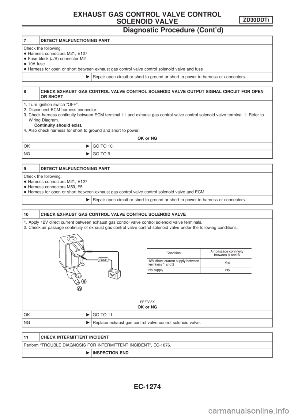
10 CHECK EXHAUST GAS CONTROL VALVE CONTROL SOLENOID VALVE
1. Apply 12V direct current between exhaust gas control valve control solenoid valve terminals.
2. Check air passage continuity of exhaust gas control valve control solenoid valve under the following conditions.
SEF335X
OK or NG
OKcGO TO 11.
NGcReplace exhaust gas control valve control solenoid valve.
11 CHECK INTERMITTENT INCIDENT
Perform ªTROUBLE DIAGNOSIS FOR INTERMITTENT INCIDENTº, EC-1076.
cINSPECTION END
EXHAUST GAS CONTROL VALVE CONTROL
SOLENOID VALVEZD30DDTi
Diagnostic Procedure (Cont'd)
EC-1274
Page 512 of 1033
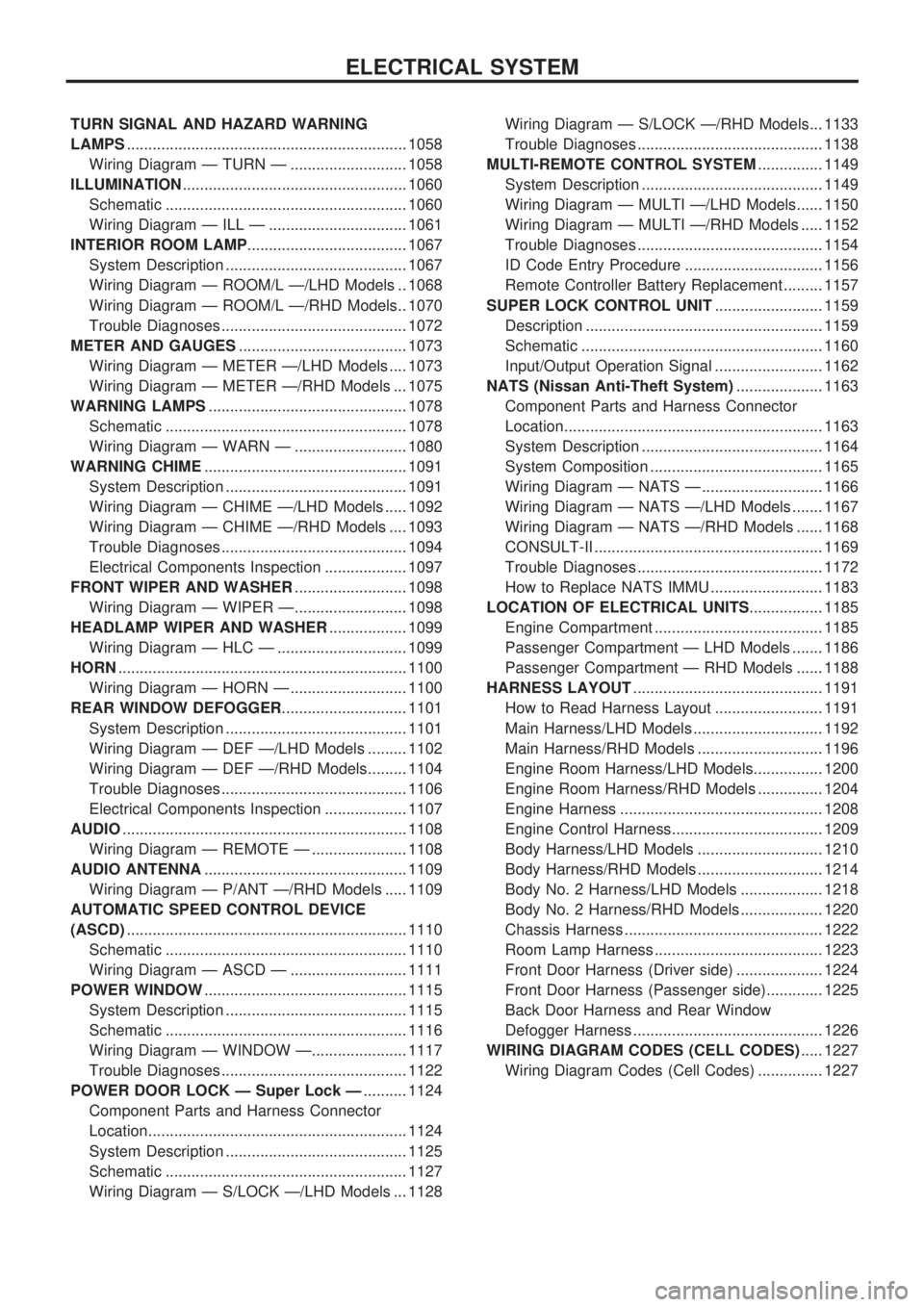
TURN SIGNAL AND HAZARD WARNING
LAMPS................................................................. 1058
Wiring Diagram Ð TURN Ð ........................... 1058
ILLUMINATION .................................................... 1060
Schematic ........................................................ 1060
Wiring Diagram Ð ILL Ð ................................ 1061
INTERIOR ROOM LAMP ..................................... 1067
System Description .......................................... 1067
Wiring Diagram Ð ROOM/L Ð/LHD Models .. 1068
Wiring Diagram Ð ROOM/L Ð/RHD Models.. 1070
Trouble Diagnoses ........................................... 1072
METER AND GAUGES ....................................... 1073
Wiring Diagram Ð METER Ð/LHD Models .... 1073
Wiring Diagram Ð METER Ð/RHD Models ... 1075
WARNING LAMPS .............................................. 1078
Schematic ........................................................ 1078
Wiring Diagram Ð WARN Ð .......................... 1080
WARNING CHIME ............................................... 1091
System Description .......................................... 1091
Wiring Diagram Ð CHIME Ð/LHD Models ..... 1092
Wiring Diagram Ð CHIME Ð/RHD Models .... 1093
Trouble Diagnoses ........................................... 1094
Electrical Components Inspection ................... 1097
FRONT WIPER AND WASHER .......................... 1098
Wiring Diagram Ð WIPER Ð.......................... 1098
HEADLAMP WIPER AND WASHER .................. 1099
Wiring Diagram Ð HLC Ð .............................. 1099
HORN ................................................................... 1100
Wiring Diagram Ð HORN Ð ........................... 1100
REAR WINDOW DEFOGGER ............................. 1101
System Description .......................................... 1101
Wiring Diagram Ð DEF Ð/LHD Models ......... 1102
Wiring Diagram Ð DEF Ð/RHD Models......... 1104
Trouble Diagnoses ........................................... 1106
Electrical Components Inspection ................... 1107
AUDIO .................................................................. 1108
Wiring Diagram Ð REMOTE Ð ...................... 1108
AUDIO ANTENNA ............................................... 1109
Wiring Diagram Ð P/ANT Ð/RHD Models ..... 1109
AUTOMATIC SPEED CONTROL DEVICE
(ASCD) ................................................................. 1110
Schematic ........................................................ 1110
Wiring Diagram Ð ASCD Ð ........................... 1111
POWER WINDOW ............................................... 1115
System Description .......................................... 1115
Schematic ........................................................ 1116
Wiring Diagram Ð WINDOW Ð...................... 1117
Trouble Diagnoses ........................................... 1122
POWER DOOR LOCK Ð Super Lock Ð .......... 1124
Component Parts and Harness Connector
Location............................................................ 1124
System Description .......................................... 1125
Schematic ........................................................ 1127
Wiring Diagram Ð S/LOCK Ð/LHD Models ... 1128 Wiring Diagram Ð S/LOCK Ð/RHD Models... 1133
Trouble Diagnoses ........................................... 1138
MULTI-REMOTE CONTROL SYSTEM ............... 1149
System Description .......................................... 1149
Wiring Diagram Ð MULTI Ð/LHD Models...... 1150
Wiring Diagram Ð MULTI Ð/RHD Models ..... 1152
Trouble Diagnoses ........................................... 1154
ID Code Entry Procedure ................................ 1156
Remote Controller Battery Replacement ......... 1157
SUPER LOCK CONTROL UNIT ......................... 1159
Description ....................................................... 1159
Schematic ........................................................ 1160
Input/Output Operation Signal ......................... 1162
NATS (Nissan Anti-Theft System) .................... 1163
Component Parts and Harness Connector
Location............................................................ 1163
System Description .......................................... 1164
System Composition ........................................ 1165
Wiring Diagram Ð NATS Ð ............................ 1166
Wiring Diagram Ð NATS Ð/LHD Models ....... 1167
Wiring Diagram Ð NATS Ð/RHD Models ...... 1168
CONSULT-II ..................................................... 1169
Trouble Diagnoses ........................................... 1172
How to Replace NATS IMMU .......................... 1183
LOCATION OF ELECTRICAL UNITS ................. 1185
Engine Compartment ....................................... 1185
Passenger Compartment Ð LHD Models ....... 1186
Passenger Compartment Ð RHD Models ...... 1188
HARNESS LAYOUT ............................................ 1191
How to Read Harness Layout ......................... 1191
Main Harness/LHD Models .............................. 1192
Main Harness/RHD Models ............................. 1196
Engine Room Harness/LHD Models................ 1200
Engine Room Harness/RHD Models ............... 1204
Engine Harness ............................................... 1208
Engine Control Harness................................... 1209
Body Harness/LHD Models ............................. 1210
Body Harness/RHD Models ............................. 1214
Body No. 2 Harness/LHD Models ................... 1218
Body No. 2 Harness/RHD Models ................... 1220
Chassis Harness .............................................. 1222
Room Lamp Harness ....................................... 1223
Front Door Harness (Driver side) .................... 1224
Front Door Harness (Passenger side)............. 1225
Back Door Harness and Rear Window
Defogger Harness ............................................ 1226
WIRING DIAGRAM CODES (CELL CODES) ..... 1227
Wiring Diagram Codes (Cell Codes) ............... 1227
ELECTRICAL SYSTEM
Page 565 of 1033
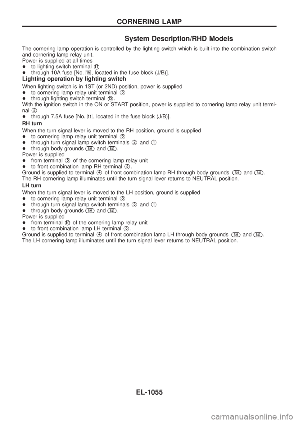
System Description/RHD Models
The cornering lamp operation is controlled by the lighting switch which is built into the combination switch
and cornering lamp relay unit.
Power is supplied at all times
+to lighting switch terminal
V11
+through 10A fuse [No.15, located in the fuse block (J/B)].
Lighting operation by lighting switch
When lighting switch is in 1ST (or 2ND) position, power is supplied
+to cornering lamp relay unit terminal
V3
+through lighting switch terminalV12.
With the ignition switch in the ON or START position, power is supplied to cornering lamp relay unit termi-
nal
V2
+through 7.5A fuse [No.11, located in the fuse block (J/B)].
RH turn
When the turn signal lever is moved to the RH position, ground is supplied
+to cornering lamp relay unit terminal
V6
+through turn signal lamp switch terminalsV2andV1
+through body groundsE25andE40.
Power is supplied
+from terminal
V5of the cornering lamp relay unit
+to front combination lamp RH terminal
V3.
Ground is supplied to terminal
V4of front combination lamp RH through body groundsE25andE40.
The RH cornering lamp illuminates until the turn signal lever returns to NEUTRAL position.
LH turn
When the turn signal lever is moved to the LH position, ground is supplied
+to cornering lamp relay unit terminal
V8
+through turn signal lamp switch terminalsV3andV1
+through body groundsE25andE40.
Power is supplied
+from terminal
V10of the cornering lamp relay unit
+to front combination lamp LH terminal
V3.
Ground is supplied to terminal
V4of front combination lamp LH through body groundsE25andE40.
The LH cornering lamp illuminates until the turn signal lever returns to NEUTRAL position.
CORNERING LAMP
EL-1055
Page 567 of 1033
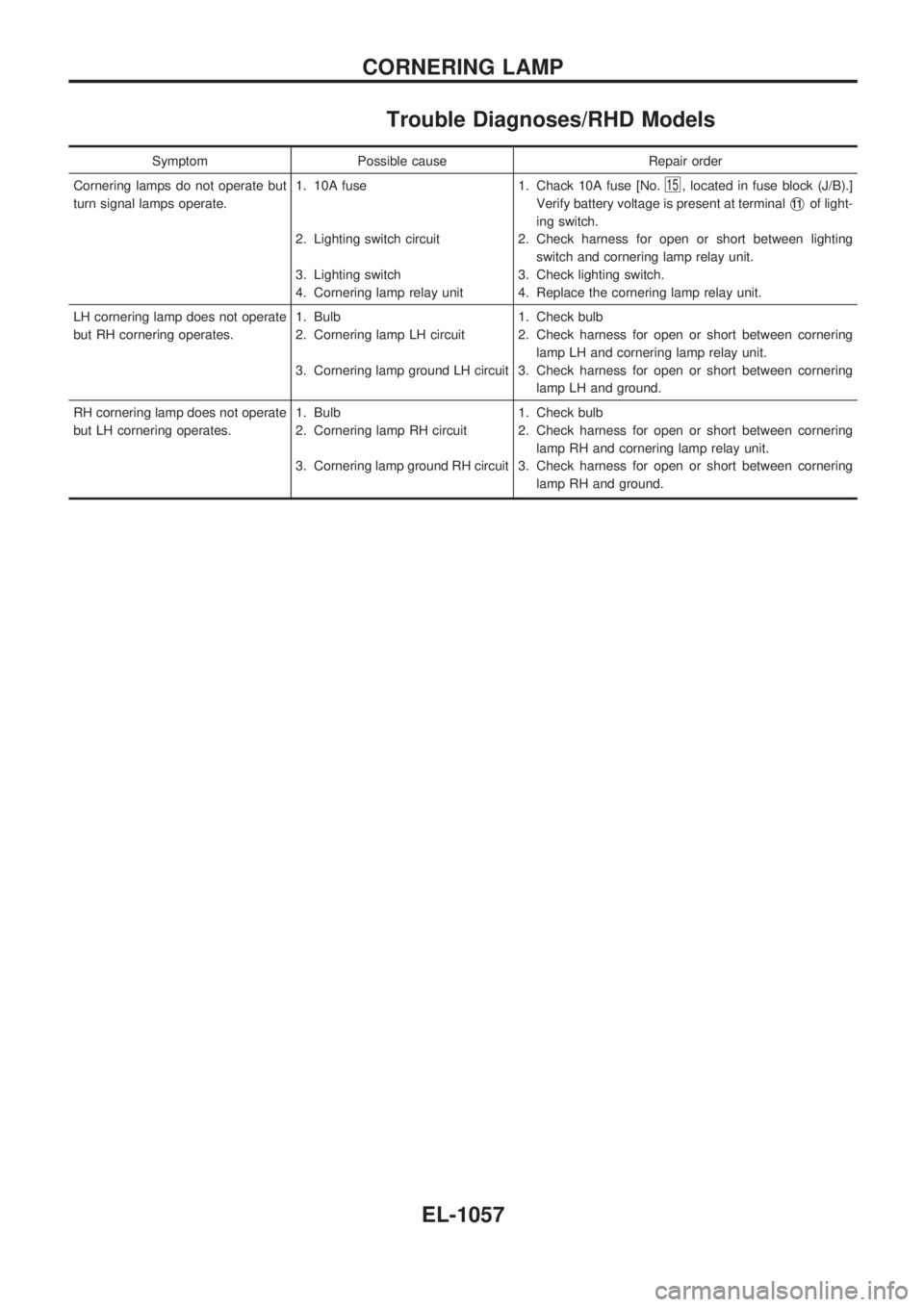
Trouble Diagnoses/RHD Models
Symptom Possible cause Repair order
Cornering lamps do not operate but
turn signal lamps operate.1. 10A fuse
2. Lighting switch circuit
3. Lighting switch
4. Cornering lamp relay unit1. Chack 10A fuse [No.
15, located in fuse block (J/B).]
Verify battery voltage is present at terminal
V11of light-
ing switch.
2. Check harness for open or short between lighting
switch and cornering lamp relay unit.
3. Check lighting switch.
4. Replace the cornering lamp relay unit.
LH cornering lamp does not operate
but RH cornering operates.1. Bulb
2. Cornering lamp LH circuit
3. Cornering lamp ground LH circuit1. Check bulb
2. Check harness for open or short between cornering
lamp LH and cornering lamp relay unit.
3. Check harness for open or short between cornering
lamp LH and ground.
RH cornering lamp does not operate
but LH cornering operates.1. Bulb
2. Cornering lamp RH circuit
3. Cornering lamp ground RH circuit1. Check bulb
2. Check harness for open or short between cornering
lamp RH and cornering lamp relay unit.
3. Check harness for open or short between cornering
lamp RH and ground.
CORNERING LAMP
EL-1057
Page 568 of 1033
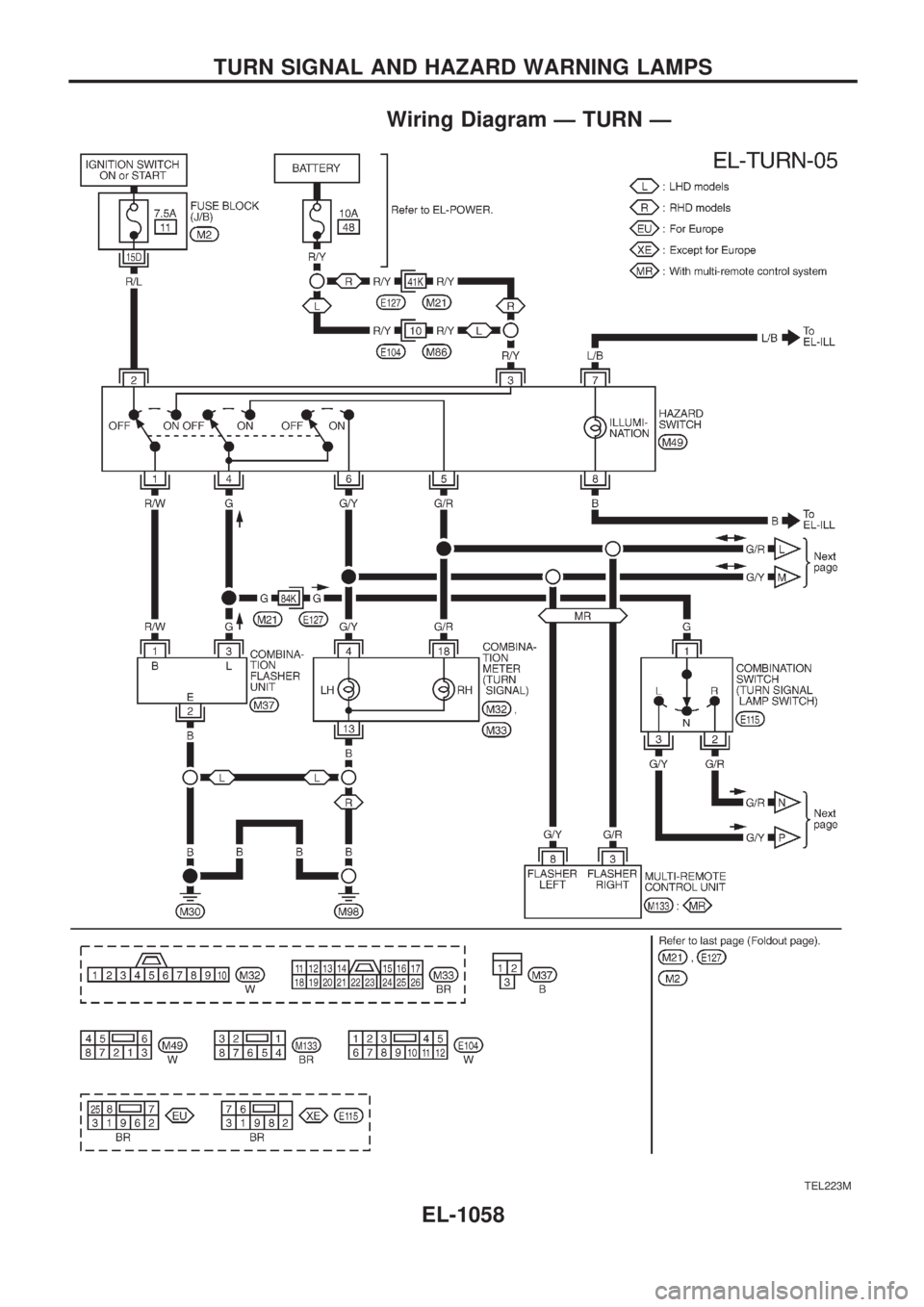
Wiring Diagram Ð TURN Ð
TEL223M
TURN SIGNAL AND HAZARD WARNING LAMPS
EL-1058