Page 431 of 1033
Diagnostic Procedure
1 CHECK ECM POWER SUPPLY CIRCUIT
1. Turn ignition switch ªOFFº.
2. Disconnect ECM relay.
SEF225Z
3. Check voltage between ECM terminals 1, 3 and ground with CONSULT-II or tester.
SEF289Z
OK or NG
OKcGO TO 3.
NGcGO TO 2.
2 DETECT MALFUNCTIONING PART
Check the following.
1. Harness connectors E104, M86 or E127, M21
2. 20A fuse
3. Harness for open and short between ECM relay and battery
cRepair open circuit or short to ground or short to power in harness or connectors.
3 CHECK ECM INPUT SIGNAL CIRCUIT FOR OPEN AND SHORT
1. Turn ignition switch ªOFFº.
2. Disconnect ECM harness connector.
3. Check harness continuity between ECM terminals 56, 61, 116 and ECM relay terminal 5. Refer to Wiring Diagram.
Continuity should exist.
4. Also check harness for short to ground and short to power.
OK or NG
OKcGO TO 5.
NGcGO TO 4.
DTC 0902 ECM RLYZD30DDTi
EC-1198
Page 433 of 1033
Description
The ECM consists of a microcomputer and connectors for signal
input and output and for power supply. The unit controls the
engine.
On Board Diagnosis Logic
Malfunction is detected when ... Check Items (Possible Cause)
+ECM input signal processing function is malfunctioning.+ECM
(ECCS-D control module)
DTC Confirmation Procedure
WITH CONSULT-II
1) Turn ignition switch ªONº.
2) Select ªDATA MONITORº mode with CONSULT-II.
3) Turn ignition switch ªOFFº, wait at least 20 seconds and then
turn ªONº.
4) If DTC is detected, go to ªDiagnostic Procedureº, EC-1201.
WITHOUT CONSULT-II
1) Turn ignition switch ªONº and wait at least 2 seconds.
2) Turn ignition switch ªOFFº, wait at least 20 seconds and then
turn ªONº.
3) Perform ªDiagnostic Test Mode II (Self-diagnostic results)º
with ECM.
4) If DTC is detected, go to ªDiagnostic Procedureº, EC-1201.
SEC220B
SEF817Y
DTC 0903 ECM 15ZD30DDTi
EC-1200
Page 439 of 1033

4 CHECK CHARGE AIR PRESSURE SENSOR INPUT SIGNAL CIRCUIT FOR OPEN AND SHORT
1. Disconnect ECM harness connector.
2. Check harness continuity between ECM terminal 46 and charge air pressure sensor terminal 2. Refer to Wiring Diagram.
Continuity should exist.
3. Also check harness for short to ground and short to power.
OK or NG
OKcGO TO 5.
NGcRepair open circuit or short to ground or short to power in harness or connectors.
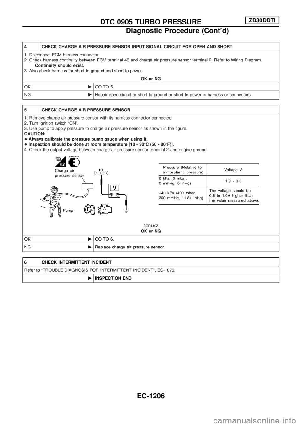
5 CHECK CHARGE AIR PRESSURE SENSOR
1. Remove charge air pressure sensor with its harness connector connected.
2. Turn ignition switch ªONº.
3. Use pump to apply pressure to charge air pressure sensor as shown in the figure.
CAUTION:
+Always calibrate the pressure pump gauge when using it.
+Inspection should be done at room temperature [10 - 30ÉC (50 - 86ÉF)].
4. Check the output voltage between charge air pressure sensor terminal 2 and engine ground.
SEF449Z
OK or NG
OKcGO TO 6.
NGcReplace charge air pressure sensor.
6 CHECK INTERMITTENT INCIDENT
Refer to ªTROUBLE DIAGNOSIS FOR INTERMITTENT INCIDENTº, EC-1076.
cINSPECTION END
DTC 0905 TURBO PRESSUREZD30DDTi
Diagnostic Procedure (Cont'd)
EC-1206
Page 441 of 1033

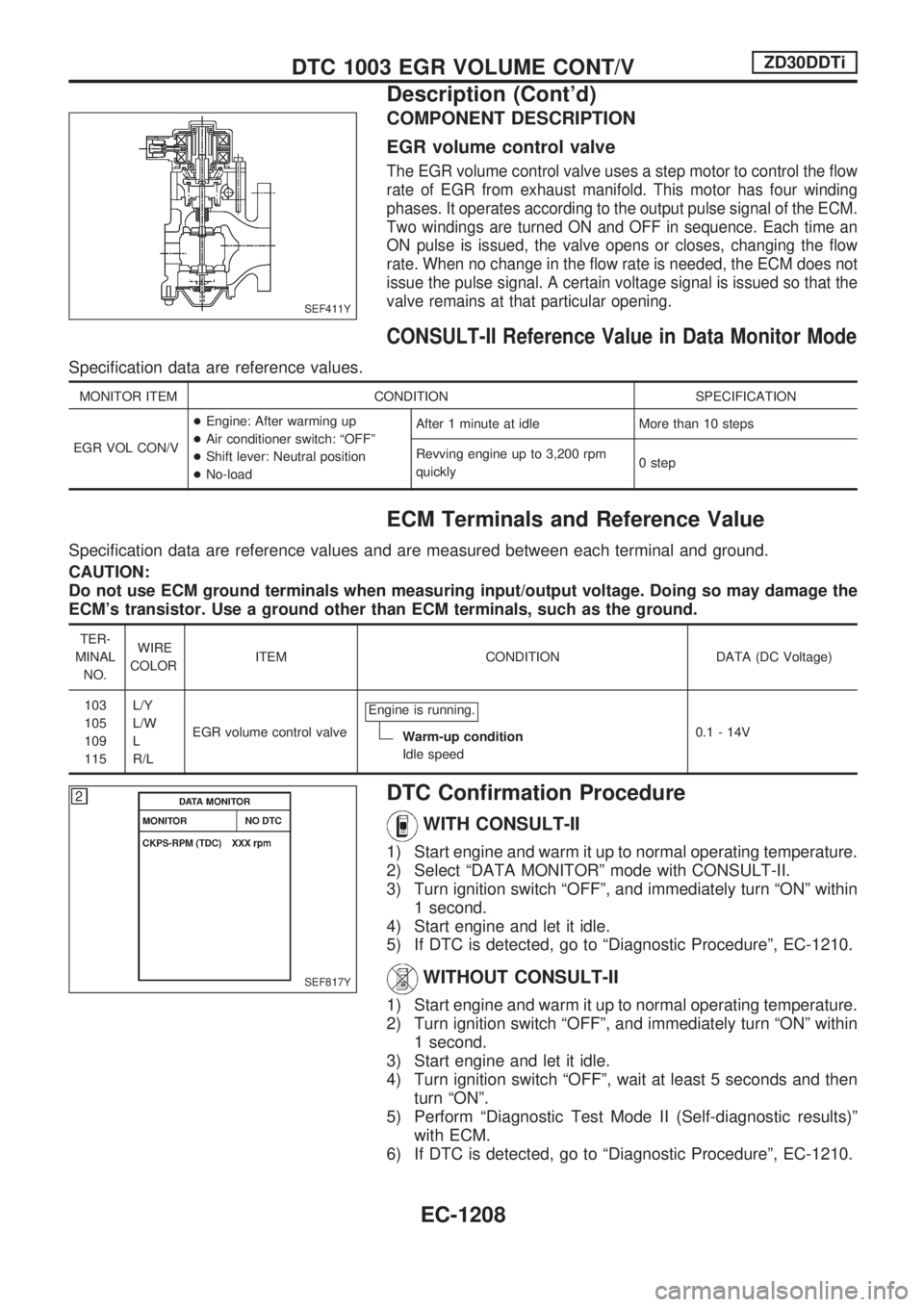
COMPONENT DESCRIPTION
EGR volume control valve
The EGR volume control valve uses a step motor to control the flow
rate of EGR from exhaust manifold. This motor has four winding
phases. It operates according to the output pulse signal of the ECM.
Two windings are turned ON and OFF in sequence. Each time an
ON pulse is issued, the valve opens or closes, changing the flow
rate. When no change in the flow rate is needed, the ECM does not
issue the pulse signal. A certain voltage signal is issued so that the
valve remains at that particular opening.
CONSULT-II Reference Value in Data Monitor Mode
Specification data are reference values.
MONITOR ITEM CONDITION SPECIFICATION
EGR VOL CON/V+Engine: After warming up
+Air conditioner switch: ªOFFº
+Shift lever: Neutral position
+No-loadAfter 1 minute at idle More than 10 steps
Revving engine up to 3,200 rpm
quickly0 step
ECM Terminals and Reference Value
Specification data are reference values and are measured between each terminal and ground.
CAUTION:
Do not use ECM ground terminals when measuring input/output voltage. Doing so may damage the
ECM's transistor. Use a ground other than ECM terminals, such as the ground.
TER-
MINAL
NO.WIRE
COLORITEM CONDITION DATA (DC Voltage)
103
105
109
115L/Y
L/W
L
R/LEGR volume control valveEngine is running.
Warm-up condition
Idle speed0.1 - 14V
DTC Confirmation Procedure
WITH CONSULT-II
1) Start engine and warm it up to normal operating temperature.
2) Select ªDATA MONITORº mode with CONSULT-II.
3) Turn ignition switch ªOFFº, and immediately turn ªONº within
1 second.
4) Start engine and let it idle.
5) If DTC is detected, go to ªDiagnostic Procedureº, EC-1210.
WITHOUT CONSULT-II
1) Start engine and warm it up to normal operating temperature.
2) Turn ignition switch ªOFFº, and immediately turn ªONº within
1 second.
3) Start engine and let it idle.
4) Turn ignition switch ªOFFº, wait at least 5 seconds and then
turn ªONº.
5) Perform ªDiagnostic Test Mode II (Self-diagnostic results)º
with ECM.
6) If DTC is detected, go to ªDiagnostic Procedureº, EC-1210.
SEF411Y
SEF817Y
DTC 1003 EGR VOLUME CONT/VZD30DDTi
Description (Cont'd)
EC-1208
Page 445 of 1033
6 CHECK ECM RELAY
1. Apply 12V direct current between ECM relay terminals 1 and 2.
2. Check continuity between ECM relay terminals 3 and 5, 6 and 7.
SEF296X
OK or NG
OKcGO TO 7.
NGcReplace ECM relay.
7 CHECK EGR VOLUME CONTROL VALVE OUTPUT SIGNAL CIRCUIT FOR OPEN AND SHORT
1. Turn ignition switch ªOFFº.
2. Disconnect ECM harness connector.
3. Check harness continuity between ECM terminals and EGR volume control valve terminals as follows.
Refer to Wiring Diagram.
MTBL0442
Continuity should exist.
4. Also check harness for short to ground and short to power.
OK or NG
OKcGO TO 8.
NGcRepair open circuit or short to ground or short to power in harness or connectors.
DTC 1003 EGR VOLUME CONT/VZD30DDTi
Diagnostic Procedure (Cont'd)
EC-1212
Page 454 of 1033

Description
SYSTEM DESCRIPTION
Sensor Input Signal to ECMECM
FunctionActuator
Crankshaft position
sensor (TDC)Engine speed
Glow
controlGlow lamp,
Glow relay
¯
Glow plugs Engine coolant tem-
perature sensorEngine coolant tem-
perature
When engine coolant temperature is more than approximately
75ÉC (167ÉF), the glow relay turns off, inactivating the quick-glow
control until coolant temperature drops below approximately
55ÉC (131ÉF).
When coolant temperature is lower than approximately 75ÉC
(167ÉF):
+Ignition switch ON
After ignition switch has turned to ON, the glow relay turns
ON for a certain period of time in relation to engine coolant
temperature, allowing current to flow through glow plug.
+Cranking
The glow relay turns ON, allowing current to flow through
glow plug.
+Starting
After engine has started, current continues to flow through
glow plug (after-glow mode) for a certain period in relation to
engine coolant temperature.
When engine speed exceeds approximately 4,800 rpm, cur-
rent flow through glow plug is interrupted.
The glow indicator lamp turns ON for a certain period of time in
relation to engine coolant temperature at the time glow relay is
turned ON.
COMPONENT DESCRIPTION
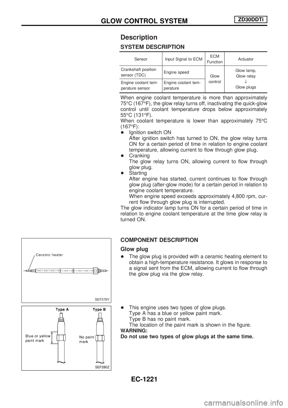
Glow plug
+The glow plug is provided with a ceramic heating element to
obtain a high-temperature resistance. It glows in response to
a signal sent from the ECM, allowing current to flow through
the glow plug via the glow relay.
+This engine uses two types of glow plugs.
Type A has a blue or yellow paint mark.
Type B has no paint mark.
The location of the paint mark is shown in the figure.
WARNING:
Do not use two types of glow plugs at the same time.
SEF376Y
SEF280Z
GLOW CONTROL SYSTEMZD30DDTi
EC-1221
Page 459 of 1033

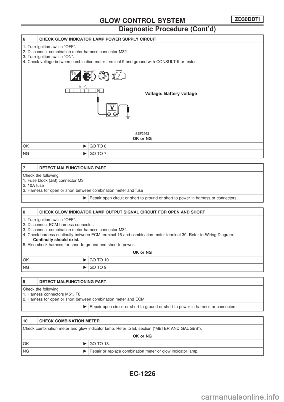
6 CHECK GLOW INDICATOR LAMP POWER SUPPLY CIRCUIT
1. Turn ignition switch ªOFFº.
2. Disconnect combination meter harness connector M32.
3. Turn ignition switch ªONº.
4. Check voltage between combination meter terminal 9 and ground with CONSULT-II or tester.
SEF296Z
OK or NG
OKcGO TO 8.
NGcGO TO 7.
7 DETECT MALFUNCTIONING PART
Check the following.
1. Fuse block (J/B) connector M3
2. 10A fuse
3. Harness for open or short between combination meter and fuse
cRepair open circuit or short to ground or short to power in harness or connectors.
8 CHECK GLOW INDICATOR LAMP OUTPUT SIGNAL CIRCUIT FOR OPEN AND SHORT
1. Turn ignition switch ªOFFº.
2. Disconnect ECM harness connector.
3. Disconnect combination meter harness connector M34.
4. Check harness continuity between ECM terminal 16 and combination meter terminal 30. Refer to Wiring Diagram.
Continuity should exist.
5. Also check harness for short to ground and short to power.
OK or NG
OKcGO TO 10.
NGcGO TO 9.
9 DETECT MALFUNCTIONING PART
Check the following.
1. Harness connectors M51, F6
2. Harness for open or short between combination meter and ECM
cRepair open circuit or short to ground or short to power in harness or connectors.
10 CHECK COMBINATION METER
Check combination meter and glow indicator lamp. Refer to EL section (ªMETER AND GAUGESº).
OK or NG
OKcGO TO 18.
NGcRepair or replace combination meter or glow indicator lamp.
GLOW CONTROL SYSTEMZD30DDTi
Diagnostic Procedure (Cont'd)
EC-1226
Page 460 of 1033
11 CHECK GLOW RELAY POWER SUPPLY CIRCUIT
1. Turn ignition switch ªOFFº.
2. Disconnect glow relay.
SEF235Z
3. Check voltage between glow relay terminals 1, 3 and ground with CONSULT-II or tester.
SEF451Z
OK or NG
OKcGO TO 13.
NGcGO TO 12.
12 DETECT MALFUNCTIONING PART
Check the following.
+100A fusible link
+Harness for open or short between glow relay and battery
cRepair harness or connectors.
13 CHECK GLOW RELAY OUTPUT SIGNAL CIRCUIT FOR OPEN AND SHORT
1. Disconnect ECM harness connector.
2. Check harness continuity between ECM terminal 111 and glow relay terminal 2. Refer to Wiring Diagram.
Continuity should exist.
3. Also check harness for short to ground and short to power.
OK or NG
OKcGO TO 15.
NGcGO TO 14.
GLOW CONTROL SYSTEMZD30DDTi
Diagnostic Procedure (Cont'd)
EC-1227