2000 NISSAN PATROL turn signal
[x] Cancel search: turn signalPage 99 of 1033
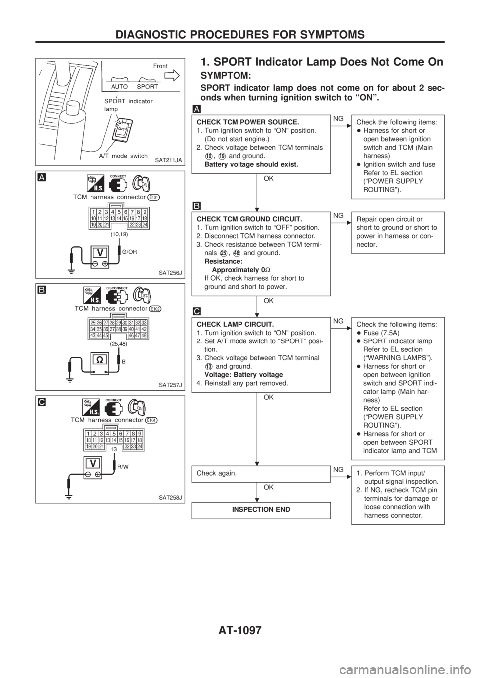
1. SPORT Indicator Lamp Does Not Come On
SYMPTOM:
SPORT indicator lamp does not come on for about 2 sec-
onds when turning ignition switch to ªONº.
CHECK TCM POWER SOURCE.
1. Turn ignition switch to ªONº position.
(Do not start engine.)
2. Check voltage between TCM terminals
V10,V19and ground.
Battery voltage should exist.
OK
cNG
Check the following items:
+Harness for short or
open between ignition
switch and TCM (Main
harness)
+Ignition switch and fuse
Refer to EL section
(ªPOWER SUPPLY
ROUTINGº).
CHECK TCM GROUND CIRCUIT.
1. Turn ignition switch to ªOFFº position.
2. Disconnect TCM harness connector.
3. Check resistance between TCM termi-
nals
V25,V48and ground.
Resistance:
Approximately 0W
If OK, check harness for short to
ground and short to power.
OK
cNG
Repair open circuit or
short to ground or short to
power in harness or con-
nector.
CHECK LAMP CIRCUIT.
1. Turn ignition switch to ªONº position.
2. Set A/T mode switch to ªSPORTº posi-
tion.
3. Check voltage between TCM terminal
V13and ground.
Voltage: Battery voltage
4. Reinstall any part removed.
OK
cNG
Check the following items:
+Fuse (7.5A)
+SPORT indicator lamp
Refer to EL section
(ªWARNING LAMPSº).
+Harness for short or
open between ignition
switch and SPORT indi-
cator lamp (Main har-
ness)
Refer to EL section
(ªPOWER SUPPLY
ROUTINGº).
+Harness for short or
open between SPORT
indicator lamp and TCM
Check again.
OK
cNG
1. Perform TCM input/
output signal inspection.
2. If NG, recheck TCM pin
terminals for damage or
loose connection with
harness connector.
INSPECTION END
SAT211JA
SAT256J
SAT257J
SAT258J
.
.
. .
.
DIAGNOSTIC PROCEDURES FOR SYMPTOMS
AT-1097
Page 113 of 1033
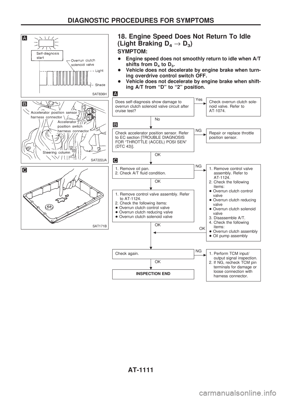
18. Engine Speed Does Not Return To Idle
(Light Braking D
4®D3)
SYMPTOM:
+Engine speed does not smoothly return to idle when A/T
shifts from D
4to D3.
+Vehicle does not decelerate by engine brake when turn-
ing overdrive control switch OFF.
+Vehicle does not decelerate by engine brake when shift-
ing A/T from ªDº to ª2º position.
Does self-diagnosis show damage to
overrun clutch solenoid valve circuit after
cruise test?
No
cYes
Check overrun clutch sole-
noid valve. Refer to
AT-1074.
Check accelerator position sensor. Refer
to EC section [TROUBLE DIAGNOSIS
FOR ªTHROTTLE (ACCEL) POSI SENº
(DTC 43)].
OK
cNG
Repair or replace throttle
position sensor.
1. Remove oil pan.
2. Check A/T fluid condition.
OK
cNG
1. Remove control valve
assembly. Refer to
AT-1124.
2. Check the following
items:
+Overrun clutch control
valve
+Overrun clutch reducing
valve
+Overrun clutch solenoid
valve
3. Disassemble A/T.
4. Check the following
items:
+Overrun clutch assembly
+Oil pump assembly
1. Remove control valve assembly. Refer
to AT-1124.
2. Check the following items:
+Overrun clutch control valve
+Overrun clutch reducing valve
+Overrun clutch solenoid valve
OK
OK
b
Check again.
OK
cNG
1. Perform TCM input/
output signal inspection.
2. If NG, recheck TCM pin
terminals for damage or
loose connection with
harness connector.
INSPECTION END
SAT836H
SAT222JA
SAT171B
.
.
.
. .
.
DIAGNOSTIC PROCEDURES FOR SYMPTOMS
AT-1111
Page 117 of 1033
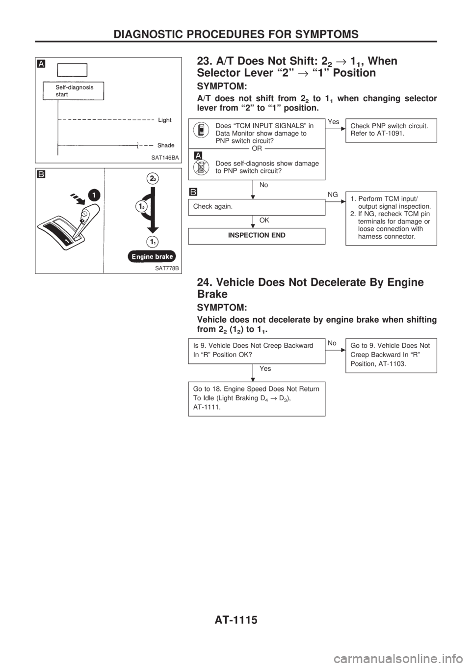
23. A/T Does Not Shift: 22®11, When
Selector Lever ª2º®ª1º Position
SYMPTOM:
A/T does not shift from 22to 11when changing selector
lever from ª2º to ª1º position.
Does ªTCM INPUT SIGNALSº in
Data Monitor show damage to
PNP switch circuit?
------------------------------------------------------------------------------------------------------------------------------------OR------------------------------------------------------------------------------------------------------------------------------------
Does self-diagnosis show damage
to PNP switch circuit?
No
cYes
Check PNP switch circuit.
Refer to AT-1091.
Check again.
OK
cNG
1. Perform TCM input/
output signal inspection.
2. If NG, recheck TCM pin
terminals for damage or
loose connection with
harness connector.
INSPECTION END
24. Vehicle Does Not Decelerate By Engine
Brake
SYMPTOM:
Vehicle does not decelerate by engine brake when shifting
from 2
2(12)to11.
Is 9. Vehicle Does Not Creep Backward
In ªRº Position OK?
Yes
cNo
Go to 9. Vehicle Does Not
Creep Backward In ªRº
Position, AT-1103.
Go to 18. Engine Speed Does Not Return
To Idle (Light Braking D
4®D3),
AT-1111.
SAT146BA
SAT778B
.
.
.
DIAGNOSTIC PROCEDURES FOR SYMPTOMS
AT-1115
Page 120 of 1033
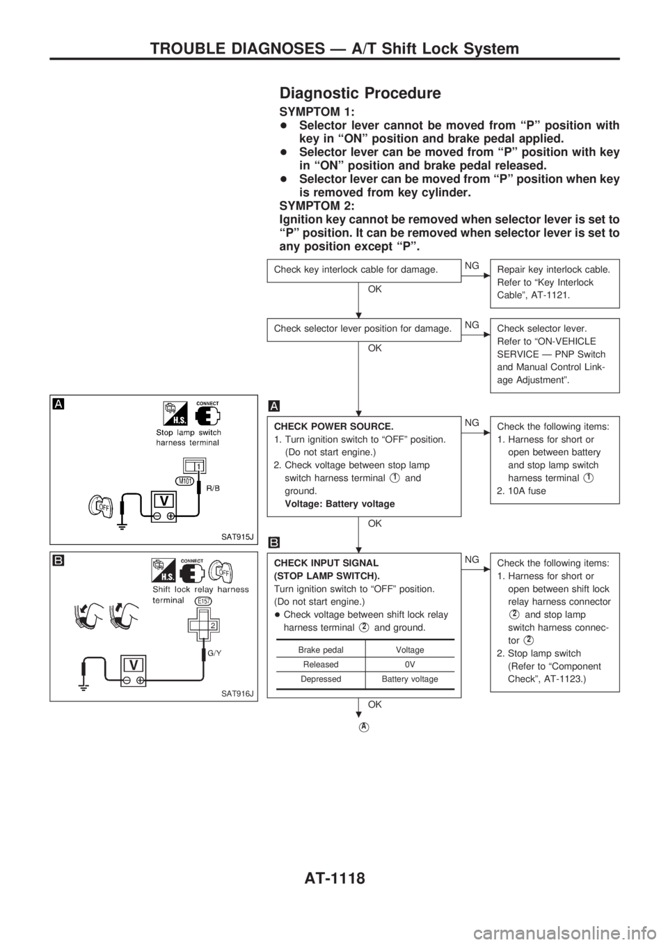
Diagnostic Procedure
SYMPTOM 1:
+Selector lever cannot be moved from ªPº position with
key in ªONº position and brake pedal applied.
+Selector lever can be moved from ªPº position with key
in ªONº position and brake pedal released.
+Selector lever can be moved from ªPº position when key
is removed from key cylinder.
SYMPTOM 2:
Ignition key cannot be removed when selector lever is set to
ªPº position. It can be removed when selector lever is set to
any position except ªPº.
Check key interlock cable for damage.
OK
cNG
Repair key interlock cable.
Refer to ªKey Interlock
Cableº, AT-1121.
Check selector lever position for damage.
OK
cNG
Check selector lever.
Refer to ªON-VEHICLE
SERVICE Ð PNP Switch
and Manual Control Link-
age Adjustmentº.
CHECK POWER SOURCE.
1. Turn ignition switch to ªOFFº position.
(Do not start engine.)
2. Check voltage between stop lamp
switch harness terminal
V1and
ground.
Voltage: Battery voltage
OK
cNG
Check the following items:
1. Harness for short or
open between battery
and stop lamp switch
harness terminal
V1
2. 10A fuse
CHECK INPUT SIGNAL
(STOP LAMP SWITCH).
Turn ignition switch to ªOFFº position.
(Do not start engine.)
+Check voltage between shift lock relay
harness terminal
V2and ground.
OK
cNG
Check the following items:
1. Harness for short or
open between shift lock
relay harness connector
V2and stop lamp
switch harness connec-
tor
V2
2. Stop lamp switch
(Refer to ªComponent
Checkº, AT-1123.)
VA
Brake pedal Voltage
Released 0V
Depressed Battery voltage
SAT915J
SAT916J
.
.
.
.
TROUBLE DIAGNOSES Ð A/T Shift Lock System
AT-1118
Page 121 of 1033
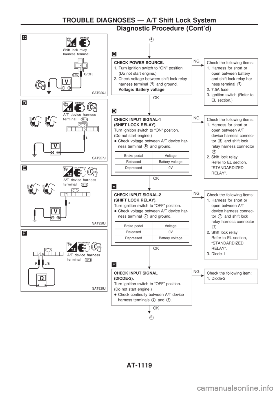
VA
CHECK POWER SOURCE.
1. Turn ignition switch to ªONº position.
(Do not start engine.)
2. Check voltage between shift lock relay
harness terminal
V4and ground.
Voltage: Battery voltage
OK
cNG
Check the following items:
1. Harness for short or
open between battery
and shift lock relay har-
ness terminal
V4
2. 7.5A fuse
3. Ignition switch (Refer to
EL section.)
CHECK INPUT SIGNAL-1
(SHIFT LOCK RELAY).
Turn ignition switch to ªONº position.
(Do not start engine.)
+Check voltage between A/T device har-
ness terminal
V5and ground.
OK
cNG
Check the following items:
1. Harness for short or
open between A/T
device harness connec-
tor
V5and shift lock
relay harness connector
V3
2. Shift lock relay
Refer to EL section,
ªSTANDARDIZED
RELAYº.
CHECK INPUT SIGNAL-2
(SHIFT LOCK RELAY).
Turn ignition switch to ªOFFº position.
+Check voltage between A/T device har-
ness terminal
V7and ground.
OK
cNG
Check the following items:
1. Harness for short or
open between A/T
device harness connec-
tor
V7and shift lock
relay harness connector
V1
2. Shift lock relay
Refer to EL section,
ªSTANDARDIZED
RELAYº.
3. Diode-1
CHECK INPUT SIGNAL
(DIODE-2).
Turn ignition switch to ªOFFº position.
(Do not start engine.)
+Check continuity between A/T device
harness terminals
V6andV7.
OK
cNG
Check the following item:
1. Diode-2
VB
Brake pedal Voltage
Released Battery voltage
Depressed 0V
Brake pedal Voltage
Released 0V
Depressed Battery voltage
SAT926J
SAT927J
SAT928J
SAT929J
.
.
.
.
.
TROUBLE DIAGNOSES Ð A/T Shift Lock System
Diagnostic Procedure (Cont'd)
AT-1119
Page 122 of 1033
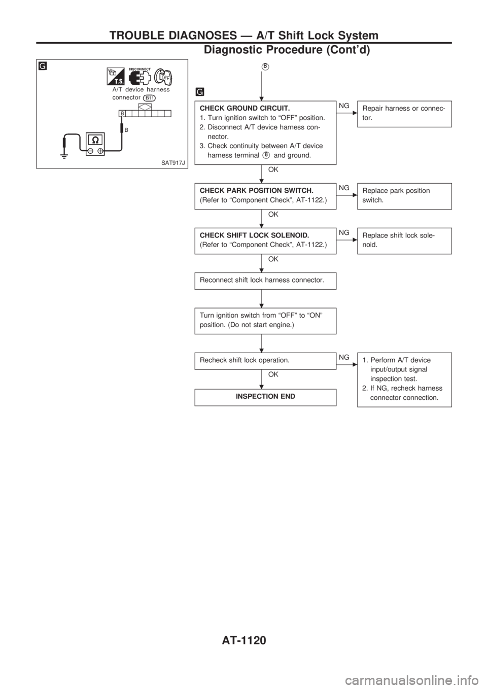
VB
CHECK GROUND CIRCUIT.
1. Turn ignition switch to ªOFFº position.
2. Disconnect A/T device harness con-
nector.
3. Check continuity between A/T device
harness terminal
V8and ground.
OK
cNG
Repair harness or connec-
tor.
CHECK PARK POSITION SWITCH.
(Refer to ªComponent Checkº, AT-1122.)
OK
cNG
Replace park position
switch.
CHECK SHIFT LOCK SOLENOID.
(Refer to ªComponent Checkº, AT-1122.)
OK
cNG
Replace shift lock sole-
noid.
Reconnect shift lock harness connector.
Turn ignition switch from ªOFFº to ªONº
position. (Do not start engine.)
Recheck shift lock operation.
OK
cNG
1. Perform A/T device
input/output signal
inspection test.
2. If NG, recheck harness
connector connection.
INSPECTION END
SAT917J
.
.
.
.
.
.
.
TROUBLE DIAGNOSES Ð A/T Shift Lock System
Diagnostic Procedure (Cont'd)
AT-1120
Page 254 of 1033
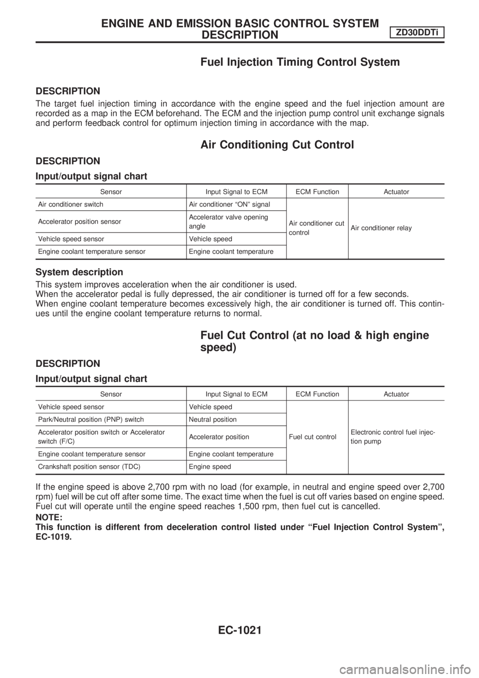
Fuel Injection Timing Control System
DESCRIPTION
The target fuel injection timing in accordance with the engine speed and the fuel injection amount are
recorded as a map in the ECM beforehand. The ECM and the injection pump control unit exchange signals
and perform feedback control for optimum injection timing in accordance with the map.
Air Conditioning Cut Control
DESCRIPTION
Input/output signal chart
Sensor Input Signal to ECM ECM Function Actuator
Air conditioner switch Air conditioner ªONº signal
Air conditioner cut
controlAir conditioner relay Accelerator position sensorAccelerator valve opening
angle
Vehicle speed sensor Vehicle speed
Engine coolant temperature sensor Engine coolant temperature
System description
This system improves acceleration when the air conditioner is used.
When the accelerator pedal is fully depressed, the air conditioner is turned off for a few seconds.
When engine coolant temperature becomes excessively high, the air conditioner is turned off. This contin-
ues until the engine coolant temperature returns to normal.
Fuel Cut Control (at no load & high engine
speed)
DESCRIPTION
Input/output signal chart
Sensor Input Signal to ECM ECM Function Actuator
Vehicle speed sensor Vehicle speed
Fuel cut controlElectronic control fuel injec-
tion pump Park/Neutral position (PNP) switch Neutral position
Accelerator position switch or Accelerator
switch (F/C)Accelerator position
Engine coolant temperature sensor Engine coolant temperature
Crankshaft position sensor (TDC) Engine speed
If the engine speed is above 2,700 rpm with no load (for example, in neutral and engine speed over 2,700
rpm) fuel will be cut off after some time. The exact time when the fuel is cut off varies based on engine speed.
Fuel cut will operate until the engine speed reaches 1,500 rpm, then fuel cut is cancelled.
NOTE:
This function is different from deceleration control listed under ªFuel Injection Control Systemº,
EC-1019.
ENGINE AND EMISSION BASIC CONTROL SYSTEM
DESCRIPTIONZD30DDTi
EC-1021
Page 295 of 1033
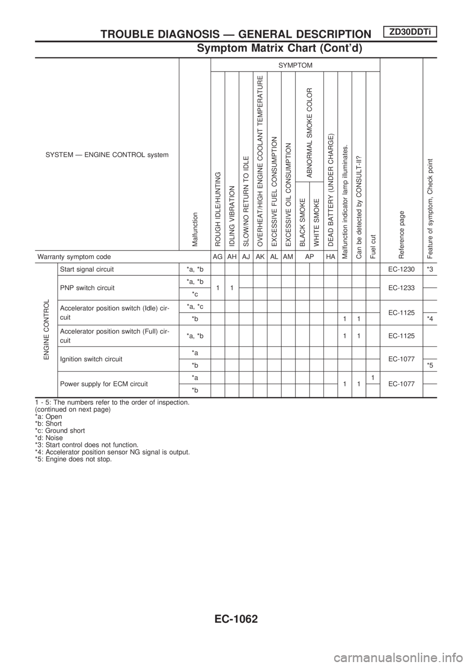
SYSTEM Ð ENGINE CONTROL system
Malfunction
SYMPTOM
Reference page
Feature of symptom, Check pointROUGH IDLE/HUNTING
IDLING VIBRATION
SLOW/NO RETURN TO IDLE
OVERHEAT/HIGH ENGINE COOLANT TEMPERATURE
EXCESSIVE FUEL CONSUMPTION
EXCESSIVE OIL CONSUMPTION
ABNORMAL SMOKE COLOR
DEAD BATTERY (UNDER CHARGE)
Malfunction indicator lamp illuminates.
Can be detected by CONSULT-II?
Fuel cutBLACK SMOKE
WHITE SMOKEWarranty symptom code AG AH AJ AK AL AM AP HA
ENGINE CONTROL
Start signal circuit *a, *b EC-1230 *3
PNP switch circuit*a, *b
1 1 EC-1233
*c
Accelerator position switch (Idle) cir-
cuit*a, *c
EC-1125
*b 1 1 *4
Accelerator position switch (Full) cir-
cuit*a, *b 1 1 EC-1125
Ignition switch circuit*a
EC-1077
*b*5
Power supply for ECM circuit*a
111
EC-1077
*b
1 - 5: The numbers refer to the order of inspection.
(continued on next page)
*a: Open
*b: Short
*c: Ground short
*d: Noise
*3: Start control does not function.
*4: Accelerator position sensor NG signal is output.
*5: Engine does not stop.
TROUBLE DIAGNOSIS Ð GENERAL DESCRIPTIONZD30DDTi
Symptom Matrix Chart (Cont'd)
EC-1062