Page 77 of 1033
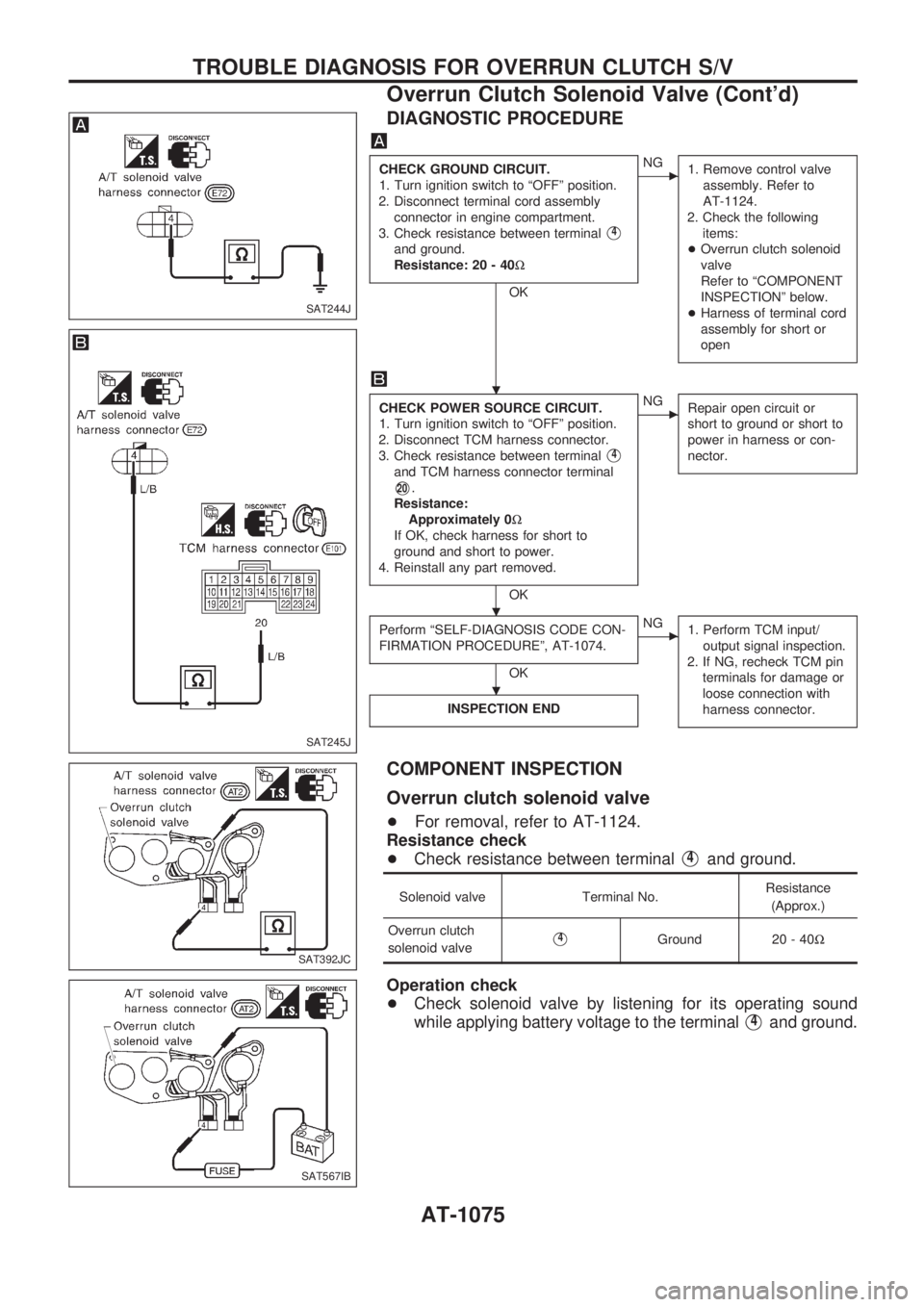
DIAGNOSTIC PROCEDURE
CHECK GROUND CIRCUIT.
1. Turn ignition switch to ªOFFº position.
2. Disconnect terminal cord assembly
connector in engine compartment.
3. Check resistance between terminal
V4
and ground.
Resistance: 20 - 40W
OK
cNG
1. Remove control valve
assembly. Refer to
AT-1124.
2. Check the following
items:
+Overrun clutch solenoid
valve
Refer to ªCOMPONENT
INSPECTIONº below.
+Harness of terminal cord
assembly for short or
open
CHECK POWER SOURCE CIRCUIT.
1. Turn ignition switch to ªOFFº position.
2. Disconnect TCM harness connector.
3. Check resistance between terminal
V4
and TCM harness connector terminal
V20.
Resistance:
Approximately 0W
If OK, check harness for short to
ground and short to power.
4. Reinstall any part removed.
OK
cNG
Repair open circuit or
short to ground or short to
power in harness or con-
nector.
Perform ªSELF-DIAGNOSIS CODE CON-
FIRMATION PROCEDUREº, AT-1074.
OK
cNG
1. Perform TCM input/
output signal inspection.
2. If NG, recheck TCM pin
terminals for damage or
loose connection with
harness connector.
INSPECTION END
COMPONENT INSPECTION
Overrun clutch solenoid valve
+For removal, refer to AT-1124.
Resistance check
+Check resistance between terminal
V4and ground.
Solenoid valve Terminal No.Resistance
(Approx.)
Overrun clutch
solenoid valve
V4Ground 20 - 40W
Operation check
+Check solenoid valve by listening for its operating sound
while applying battery voltage to the terminal
V4and ground.
SAT244J
SAT245J
SAT392JC
SAT567IB
.
.
.
TROUBLE DIAGNOSIS FOR OVERRUN CLUTCH S/V
Overrun Clutch Solenoid Valve (Cont'd)
AT-1075
Page 79 of 1033
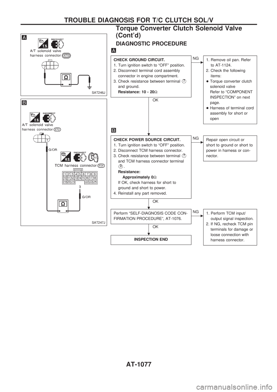
DIAGNOSTIC PROCEDURE
CHECK GROUND CIRCUIT.
1. Turn ignition switch to ªOFFº position.
2. Disconnect terminal cord assembly
connector in engine compartment.
3. Check resistance between terminal
V7
and ground.
Resistance: 10 - 20W
OK
cNG
1. Remove oil pan. Refer
to AT-1124.
2. Check the following
items:
+Torque converter clutch
solenoid valve
Refer to ªCOMPONENT
INSPECTIONº on next
page.
+Harness of terminal cord
assembly for short or
open
CHECK POWER SOURCE CIRCUIT.
1. Turn ignition switch to ªOFFº position.
2. Disconnect TCM harness connector.
3. Check resistance between terminal
V7
and TCM harness connector terminal
V3.
Resistance:
Approximately 0W
If OK, check harness for short to
ground and short to power.
4. Reinstall any part removed.
OK
cNG
Repair open circuit or
short to ground or short to
power in harness or con-
nector.
Perform ªSELF-DIAGNOSIS CODE CON-
FIRMATION PROCEDUREº, AT-1076.
OK
cNG
1. Perform TCM input/
output signal inspection.
2. If NG, recheck TCM pin
terminals for damage or
loose connection with
harness connector.
INSPECTION END
SAT246J
SAT247J
.
.
.
TROUBLE DIAGNOSIS FOR T/C CLUTCH SOL/V
Torque Converter Clutch Solenoid Valve
(Cont'd)
AT-1077
Page 87 of 1033
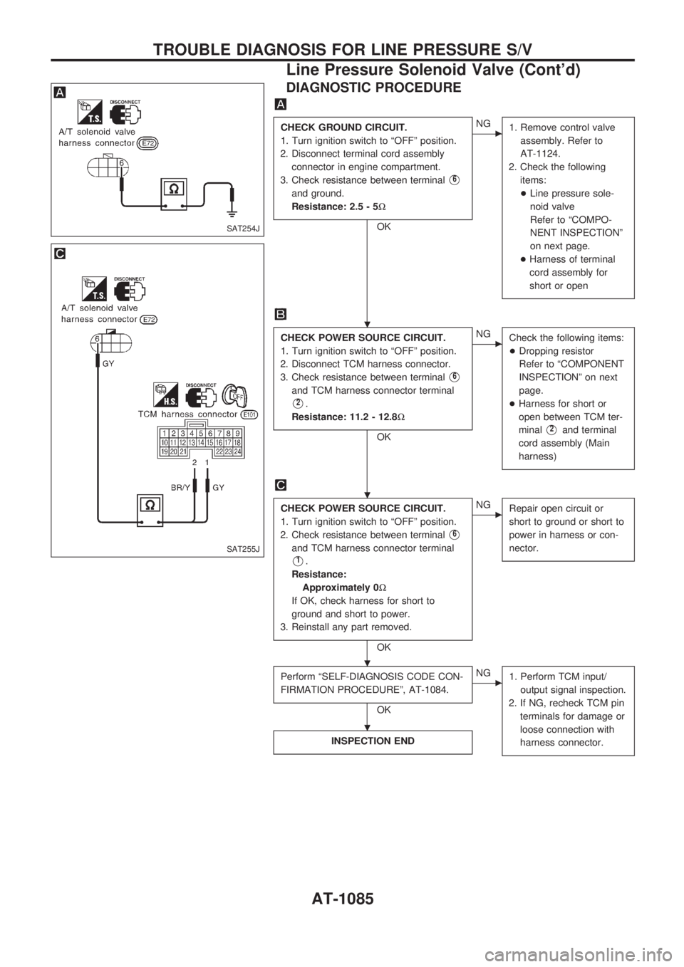
DIAGNOSTIC PROCEDURE
CHECK GROUND CIRCUIT.
1. Turn ignition switch to ªOFFº position.
2. Disconnect terminal cord assembly
connector in engine compartment.
3. Check resistance between terminal
V6
and ground.
Resistance: 2.5 - 5W
OK
cNG
1. Remove control valve
assembly. Refer to
AT-1124.
2. Check the following
items:
+Line pressure sole-
noid valve
Refer to ªCOMPO-
NENT INSPECTIONº
on next page.
+Harness of terminal
cord assembly for
short or open
CHECK POWER SOURCE CIRCUIT.
1. Turn ignition switch to ªOFFº position.
2. Disconnect TCM harness connector.
3. Check resistance between terminal
V6
and TCM harness connector terminal
V2.
Resistance: 11.2 - 12.8W
OK
cNG
Check the following items:
+Dropping resistor
Refer to ªCOMPONENT
INSPECTIONº on next
page.
+Harness for short or
open between TCM ter-
minal
V2and terminal
cord assembly (Main
harness)
CHECK POWER SOURCE CIRCUIT.
1. Turn ignition switch to ªOFFº position.
2. Check resistance between terminal
V6
and TCM harness connector terminal
V1.
Resistance:
Approximately 0W
If OK, check harness for short to
ground and short to power.
3. Reinstall any part removed.
OK
cNG
Repair open circuit or
short to ground or short to
power in harness or con-
nector.
Perform ªSELF-DIAGNOSIS CODE CON-
FIRMATION PROCEDUREº, AT-1084.
OK
cNG
1. Perform TCM input/
output signal inspection.
2. If NG, recheck TCM pin
terminals for damage or
loose connection with
harness connector.
INSPECTION END
SAT254J
SAT255J
.
.
.
.
TROUBLE DIAGNOSIS FOR LINE PRESSURE S/V
Line Pressure Solenoid Valve (Cont'd)
AT-1085
Page 89 of 1033
Description
The TCM consists of a microcomputer and connectors for signal
input and output and for power supply. The unit controls the A/T.
ON BOARD DIAGNOSIS LOGIC
Diagnostic trouble code Malfunction is detected when ...Check item
(Possible cause)
:
CONTROL UNIT (RAM)
TCM memory (RAM) or (ROM) is mal-
functioning.TCM
:CONTROL UNIT (ROM)
SELF-DIAGNOSIS CODE CONFIRMATION
PROCEDURE
NOTE:
If ªSELF-DIAGNOSIS CODE CONFIRMATION PROCEDUREº
has been previously conducted, always turn ignition switch
ªOFFº and wait at least 5 seconds before conducting the
next test.
WITH CONSULT-II
1) Turn ignition switch ªONº and select ªDATA MONITORº
mode for A/T with CONSULT-II.
2) Start engine.
3) Run engine for at least 2 seconds at idle speed.
SAT574J
SAT014K
SAT971J
TROUBLE DIAGNOSIS FOR CONTROL UNIT (RAM), CONTROL UNIT (ROM)
AT-1087
Page 91 of 1033
Description
The TCM consists of a microcomputer and connectors for signal
input and output and for power supply. The unit controls the A/T.
ON BOARD DIAGNOSIS LOGIC
Diagnostic trouble code Malfunction is detected when ... Check item (Possible cause)
: CONT UNIT (EEP ROM)TCM memory (EEP ROM) is malfunc-
tioning.TCM
SELF-DIAGNOSIS CODE CONFIRMATION
PROCEDURE
NOTE:
If ªSELF-DIAGNOSIS CODE CONFIRMATION PROCEDUREº
has been previously conducted, always turn ignition switch
ªOFFº and wait at least 5 seconds before conducting the
next test.
WITH CONSULT-II
1) Turn ignition switch ªONº and select ªDATA MONITORº
mode for A/T with CONSULT-II.
2) Start engine.
3) Run engine for at least 2 seconds at idle speed.
SAT574J
SAT014K
SAT971J
TROUBLE DIAGNOSIS FOR CONTROL UNIT (EFP ROM)
AT-1089
Page 94 of 1033
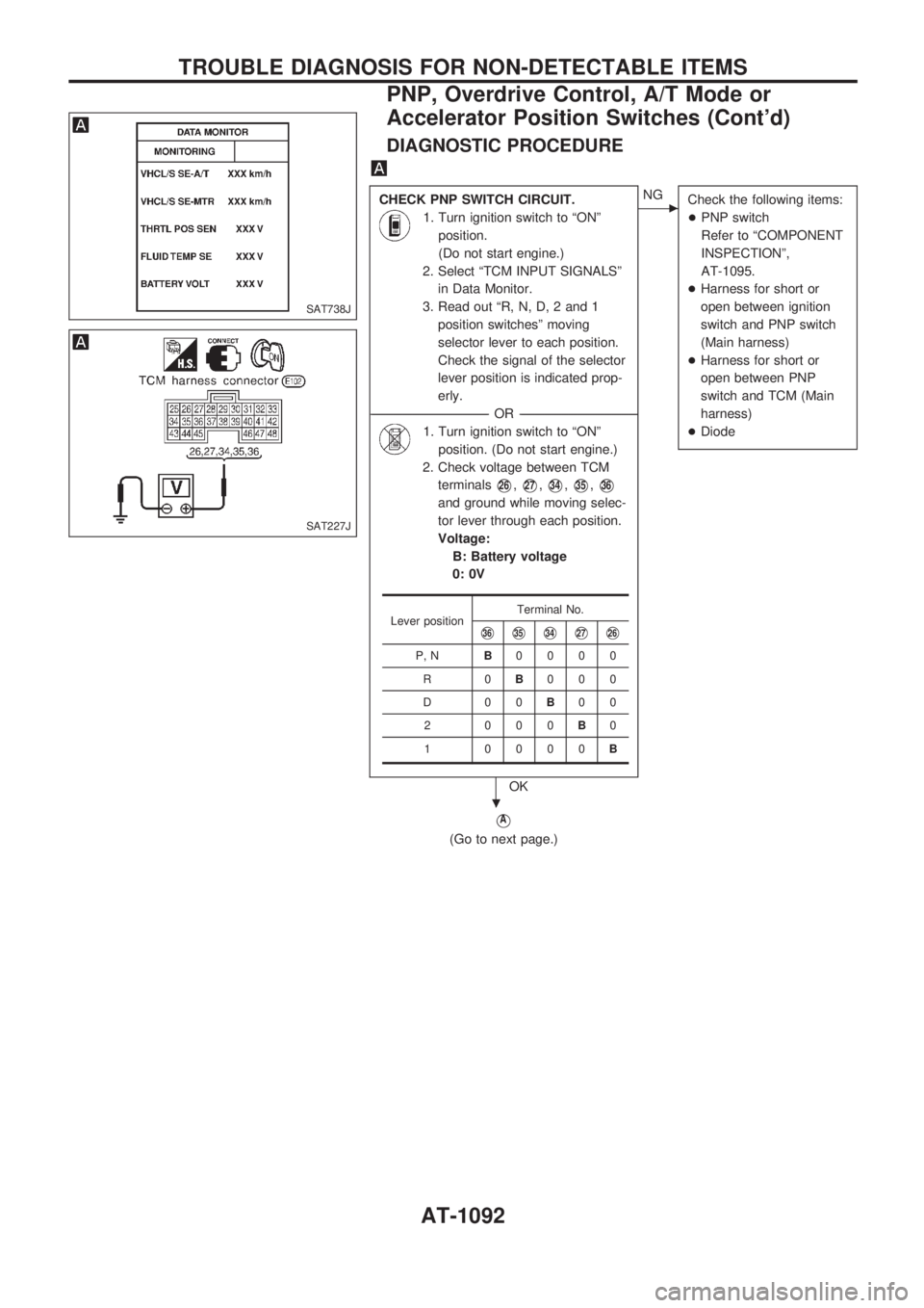
DIAGNOSTIC PROCEDURE
CHECK PNP SWITCH CIRCUIT.
1. Turn ignition switch to ªONº
position.
(Do not start engine.)
2. Select ªTCM INPUT SIGNALSº
in Data Monitor.
3. Read out ªR, N, D, 2 and 1
position switchesº moving
selector lever to each position.
Check the signal of the selector
lever position is indicated prop-
erly.
------------------------------------------------------------------------------------------------------------------------------------OR------------------------------------------------------------------------------------------------------------------------------------
1. Turn ignition switch to ªONº
position. (Do not start engine.)
2. Check voltage between TCM
terminals
V26,V27,V34,V35,V36
and ground while moving selec-
tor lever through each position.
Voltage:
B: Battery voltage
0: 0V
OK
cNG
Check the following items:
+PNP switch
Refer to ªCOMPONENT
INSPECTIONº,
AT-1095.
+Harness for short or
open between ignition
switch and PNP switch
(Main harness)
+Harness for short or
open between PNP
switch and TCM (Main
harness)
+Diode
VA
(Go to next page.)
Lever positionTerminal No.V36V35V34V27V26
P, NB0000
R0B000
D00B00
2 000B0
1 0000B
SAT738J
SAT227J
.
TROUBLE DIAGNOSIS FOR NON-DETECTABLE ITEMS
PNP, Overdrive Control, A/T Mode or
Accelerator Position Switches (Cont'd)
AT-1092
Page 95 of 1033
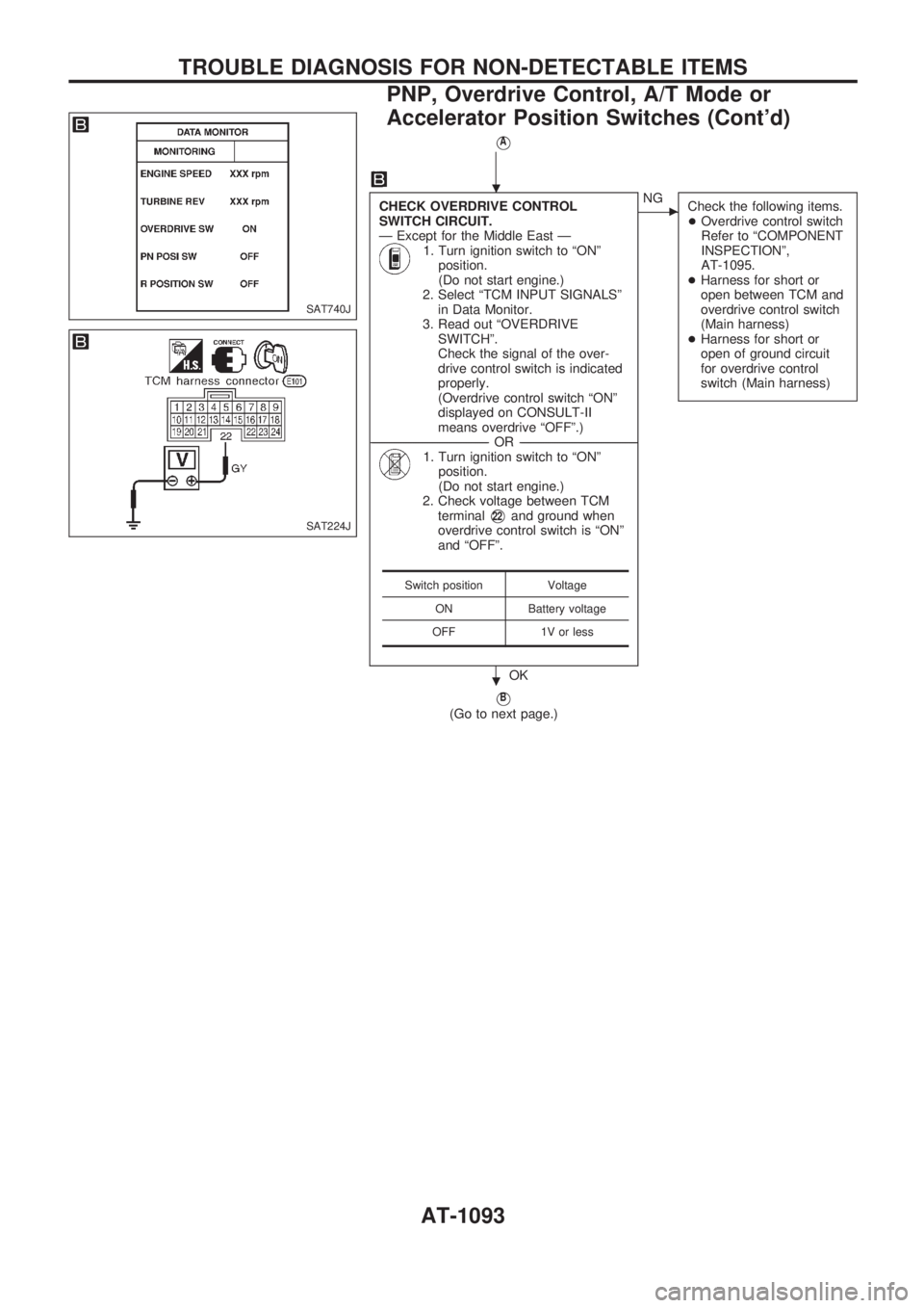
VA
CHECK OVERDRIVE CONTROL
SWITCH CIRCUIT.
Ð Except for the Middle East Ð
1. Turn ignition switch to ªONº
position.
(Do not start engine.)
2. Select ªTCM INPUT SIGNALSº
in Data Monitor.
3. Read out ªOVERDRIVE
SWITCHº.
Check the signal of the over-
drive control switch is indicated
properly.
(Overdrive control switch ªONº
displayed on CONSULT-II
means overdrive ªOFFº.)
------------------------------------------------------------------------------------------------------------------------------------OR------------------------------------------------------------------------------------------------------------------------------------
1. Turn ignition switch to ªONº
position.
(Do not start engine.)
2. Check voltage between TCM
terminal
V22and ground when
overdrive control switch is ªONº
and ªOFFº.
OK
cNG
Check the following items.
+Overdrive control switch
Refer to ªCOMPONENT
INSPECTIONº,
AT-1095.
+Harness for short or
open between TCM and
overdrive control switch
(Main harness)
+Harness for short or
open of ground circuit
for overdrive control
switch (Main harness)
VB
(Go to next page.)
Switch position Voltage
ON Battery voltage
OFF 1V or less
SAT740J
SAT224J
.
.
TROUBLE DIAGNOSIS FOR NON-DETECTABLE ITEMS
PNP, Overdrive Control, A/T Mode or
Accelerator Position Switches (Cont'd)
AT-1093
Page 96 of 1033
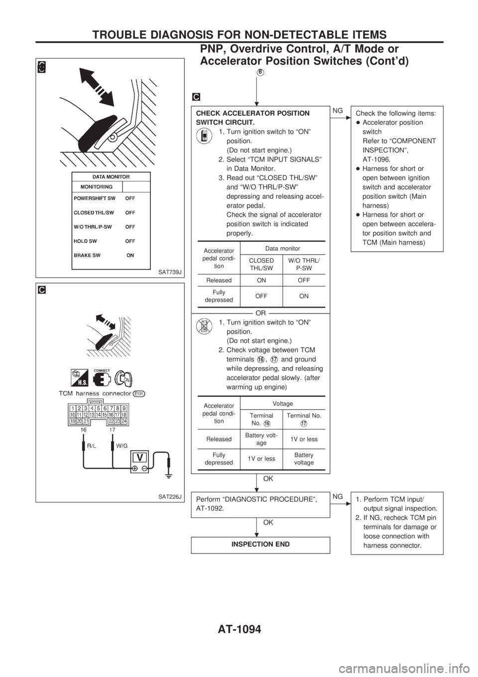
VB
CHECK ACCELERATOR POSITION
SWITCH CIRCUIT.
1. Turn ignition switch to ªONº
position.
(Do not start engine.)
2. Select ªTCM INPUT SIGNALSº
in Data Monitor.
3. Read out ªCLOSED THL/SWº
and ªW/O THRL/P-SWº
depressing and releasing accel-
erator pedal.
Check the signal of accelerator
position switch is indicated
properly.
------------------------------------------------------------------------------------------------------------------------------------OR------------------------------------------------------------------------------------------------------------------------------------
1. Turn ignition switch to ªONº
position.
(Do not start engine.)
2. Check voltage between TCM
terminals
V16,V17and ground
while depressing, and releasing
accelerator pedal slowly. (after
warming up engine)
OK
cNG
Check the following items:
+Accelerator position
switch
Refer to ªCOMPONENT
INSPECTIONº,
AT-1096.
+Harness for short or
open between ignition
switch and accelerator
position switch (Main
harness)
+Harness for short or
open between accelera-
tor position switch and
TCM (Main harness)
Perform ªDIAGNOSTIC PROCEDUREº,
AT-1092.
OK
cNG
1. Perform TCM input/
output signal inspection.
2. If NG, recheck TCM pin
terminals for damage or
loose connection with
harness connector.
INSPECTION END
Accelerator
pedal condi-
tionData monitor
CLOSED
THL/SWW/O THRL/
P-SW
Released ON OFF
Fully
depressedOFF ON
Accelerator
pedal condi-
tionVoltage
Terminal
No.
V16Terminal No.
V17
ReleasedBattery volt-
age1V or less
Fully
depressed1V or lessBattery
voltage
SAT739J
SAT226J
.
.
.
TROUBLE DIAGNOSIS FOR NON-DETECTABLE ITEMS
PNP, Overdrive Control, A/T Mode or
Accelerator Position Switches (Cont'd)
AT-1094