Page 464 of 1033

Diagnostic Procedure
1 CHECK START SIGNAL OVERALL FUNCTION
With CONSULT-II
1. Turn ignition switch ªONº.
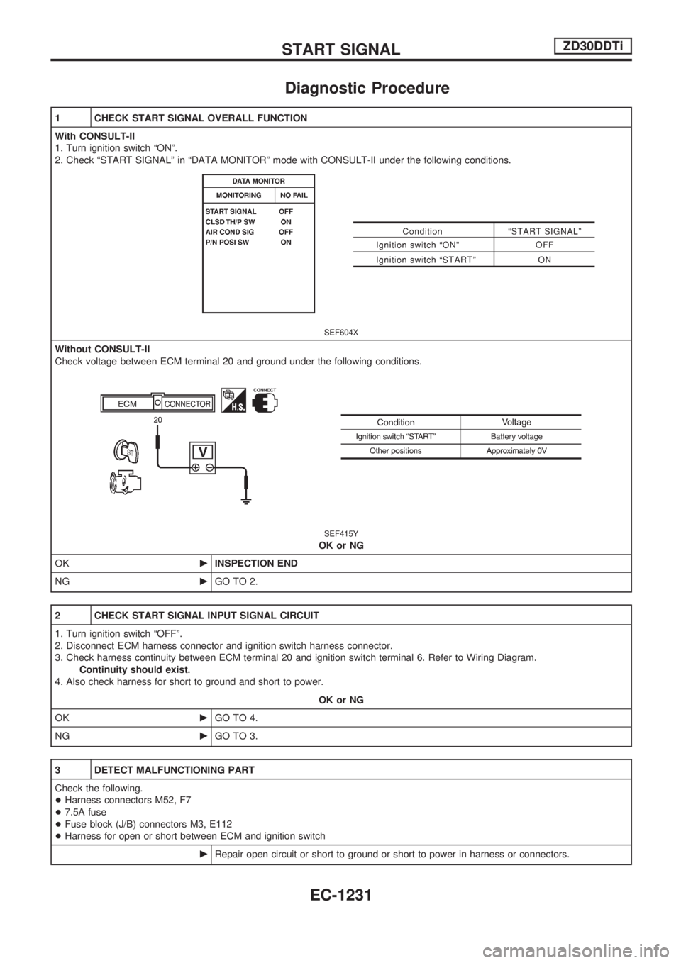
2. Check ªSTART SIGNALº in ªDATA MONITORº mode with CONSULT-II under the following conditions.
SEF604X
Without CONSULT-II
Check voltage between ECM terminal 20 and ground under the following conditions.
SEF415Y
OK or NG
OKcINSPECTION END
NGcGO TO 2.
2 CHECK START SIGNAL INPUT SIGNAL CIRCUIT
1. Turn ignition switch ªOFFº.
2. Disconnect ECM harness connector and ignition switch harness connector.
3. Check harness continuity between ECM terminal 20 and ignition switch terminal 6. Refer to Wiring Diagram.
Continuity should exist.
4. Also check harness for short to ground and short to power.
OK or NG
OKcGO TO 4.
NGcGO TO 3.
3 DETECT MALFUNCTIONING PART
Check the following.
+Harness connectors M52, F7
+7.5A fuse
+Fuse block (J/B) connectors M3, E112
+Harness for open or short between ECM and ignition switch
cRepair open circuit or short to ground or short to power in harness or connectors.
START SIGNALZD30DDTi
EC-1231
Page 468 of 1033
Diagnostic Procedure
FOR M/T MODELS
1 CHECK OVERALL FUNCTION
With CONSULT-II
1. Turn ignition switch ªONº.
2. Select ªP/N POSI SWº in ªDATA MONITORº mode with CONSULT-II.
3. Check ªP/N POSI SWº signal under the following conditions.
SEF049Y
Without CONSULT-II
1. Turn ignition switch ªONº.
2. Check voltage between ECM terminal 22 and ground under the following conditions.
SEF419Y
OK or NG
OKcINSPECTION END
NGcGO TO 2.
PARK/NEUTRAL POSITION (PNP) SWITCHZD30DDTi
EC-1235
Page 469 of 1033

2 CHECK PNP SWITCH GROUND CIRCUIT FOR OPEN AND SHORT
1. Turn ignition switch ªOFFº.
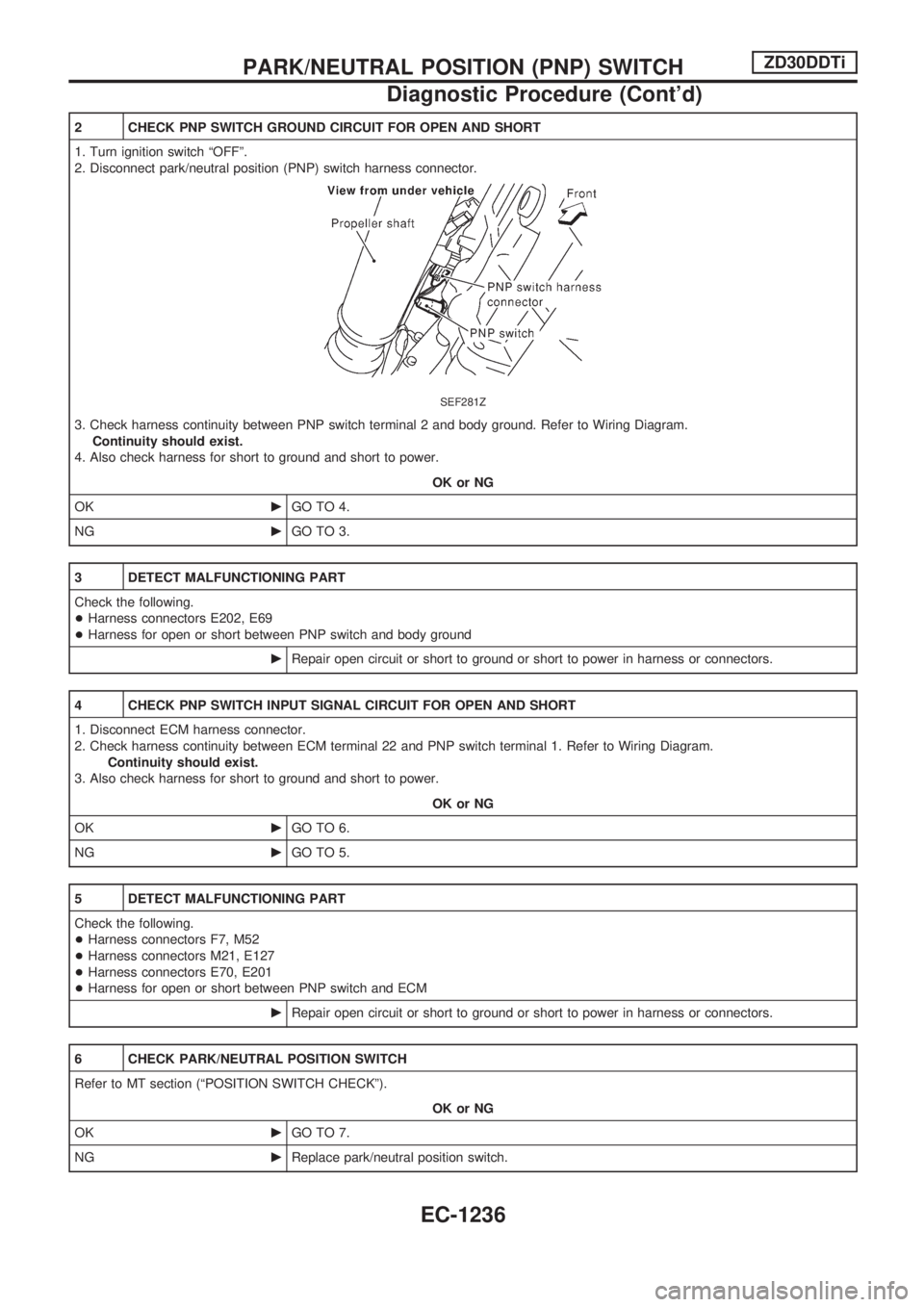
2. Disconnect park/neutral position (PNP) switch harness connector.
SEF281Z
3. Check harness continuity between PNP switch terminal 2 and body ground. Refer to Wiring Diagram.
Continuity should exist.
4. Also check harness for short to ground and short to power.
OK or NG
OKcGO TO 4.
NGcGO TO 3.
3 DETECT MALFUNCTIONING PART
Check the following.
+Harness connectors E202, E69
+Harness for open or short between PNP switch and body ground
cRepair open circuit or short to ground or short to power in harness or connectors.
4 CHECK PNP SWITCH INPUT SIGNAL CIRCUIT FOR OPEN AND SHORT
1. Disconnect ECM harness connector.
2. Check harness continuity between ECM terminal 22 and PNP switch terminal 1. Refer to Wiring Diagram.
Continuity should exist.
3. Also check harness for short to ground and short to power.
OK or NG
OKcGO TO 6.
NGcGO TO 5.
5 DETECT MALFUNCTIONING PART
Check the following.
+Harness connectors F7, M52
+Harness connectors M21, E127
+Harness connectors E70, E201
+Harness for open or short between PNP switch and ECM
cRepair open circuit or short to ground or short to power in harness or connectors.
6 CHECK PARK/NEUTRAL POSITION SWITCH
Refer to MT section (ªPOSITION SWITCH CHECKº).
OK or NG
OKcGO TO 7.
NGcReplace park/neutral position switch.
PARK/NEUTRAL POSITION (PNP) SWITCHZD30DDTi
Diagnostic Procedure (Cont'd)
EC-1236
Page 470 of 1033
7 CHECK INTERMITTENT INCIDENT
Refer to ªTROUBLE DIAGNOSIS FOR INTERMITTENT INCIDENTº, EC-1076.
cINSPECTION END
FOR A/T MODELS
1 CHECK OVERALL FUNCTION
With CONSULT-II
1. Turn ignition switch ªONº.
2. Select ªP/N POSI SWº in ªDATA MONITORº mode with CONSULT-II.
3. Check ªP/N POSI SWº signal under the following conditions.
SEF049Y
Without CONSULT-II
1. Turn ignition switch ªONº.
2. Check voltage between ECM terminal 22 and ground under the following conditions.
SEF419Y
OK or NG
OKcINSPECTION END
NGcGO TO 2.
PARK/NEUTRAL POSITION (PNP) SWITCHZD30DDTi
Diagnostic Procedure (Cont'd)
EC-1237
Page 471 of 1033
2 CHECK PNP SWITCH CIRCUIT
With CONSULT-II
1. Select ªA/Tº and then select ªP/N POSI SWº in ªDATA MONITORº mode with CONSULT-II.
2. Check ªP/N POSI SWº signal under the following conditions.
SEF049Y
OK or NG
OKcGO TO 9.
NGcGO TO 4.
3 CHECK PNP SWITCH CIRCUIT
Without CONSULT-II
1. Turn ignition switch ªOFFº.
2. Disconnect TCM (Transmission control module) harness connector.
SEF792V
3. Turn ignition switch ªONº.
4. Check voltage between TCM terminal 36 and ground under the following conditions.
SEF298Z
OK or NG
OKcGO TO 9.
NGcGO TO 4.
PARK/NEUTRAL POSITION (PNP) SWITCHZD30DDTi
Diagnostic Procedure (Cont'd)
EC-1238
Page 472 of 1033
4 CHECK PNP SWITCH POWER SUPPLY CIRCUIT
1. Turn ignition switch ªOFFº.
2. Disconnect PNP switch harness connector.
3. Turn ignition switch ªONº.
4. Check voltage between PNP switch terminal 3 and ground with CONSULT-II or tester.
SEF299Z
OK or NG
OKcGO TO 6.
NGcGO TO 5.
5 DETECT MALFUNCTIONING PART
Check the following.
+Fuse block (J/B) connector E112
+7.5A fuse
+Harness for open or short between PNP switch and fuse
cRepair open circuit or short to ground or short to power in harness or connectors.
6 CHECK PNP SWITCH INPUT SIGNAL CIRCUIT FOR OPEN OR SHORT-I
1. Turn ignition switch ªOFFº.
2. Disconnect TCM (Transmission control module) harness connector.
3. Check harness continuity between TCM terminal 36 and PNP switch terminals 7, 9 under the following conditions.
SEF300Z
4. Also check harness for short to ground and short to power.
OK or NG
OKcGO TO 8.
NGcGO TO 7.
PARK/NEUTRAL POSITION (PNP) SWITCHZD30DDTi
Diagnostic Procedure (Cont'd)
EC-1239
Page 473 of 1033

7 DETECT MALFUNCTIONING PART
Check the following.
+Diode E103
+Harness for open or short between PNP switch and TCM (Transmission control module)
cRepair open circuit or short to ground or short to power in harness or connectors.
8 CHECK PARK/NEUTRAL POSITION (PNP) SWITCH
Refer to ªTROUBLE DIAGNOSIS FOR NON-DETECTABLE ITEMSº in AT section.
OK or NG
OKcGO TO 9.
NGcReplace park/neutral position (PNP) switch.
9 CHECK PNP SWITCH INPUT SIGNAL CIRCUIT FOR OPEN OR SHORT-II
1. Turn ignition switch ªOFFº.
2. Disconnect ECM harness connector.
3. Check harness continuity between ECM terminal 22 and TCM terminal 14. Refer to Wiring Diagram.
Continuity should exist.
4. Also check harness for short to ground and short to power.
OK or NG
OKcGO TO 11.
NGcGO TO 10.
10 DETECT MALFUNCTIONING PART
Check the following.
+Harness connectors F7, M52
+Harness connectors M21, E127
+Harness for open or short between ECM and TCM (Transmission control module)
cRepair open circuit or short to ground or short to power in harness or connectors.
11 CHECK INTERMITTENT INCIDENT
Perform ªTROUBLE DIAGNOSIS FOR INTERMITTENT INCIDENTº, EC-1076.
cINSPECTION END
PARK/NEUTRAL POSITION (PNP) SWITCHZD30DDTi
Diagnostic Procedure (Cont'd)
EC-1240
Page 477 of 1033

4 CHECK HEAT UP SWITCH POWER SUPPLY CIRCUIT
1. Turn heat up switch ªOFFº.
2. Turn ignition switch ªOFFº.
3. Disconnect heat up switch harness connector.
4. Turn ignition switch ªONº.
5. Check voltage between heat up switch terminal 6 and ground with CONSULT-II or tester.
SEF304Z
OK or NG
OKcGO TO 6.
NGcGO TO 5.
5 DETECT MALFUNCTIONING PART
Check the following.
+Fuse block (J/B) connector M3
+10A fuse
+Harness for open or short between heat up switch and fuse
cRepair open circuit or short to ground or short to power in harness or connectors.
6 CHECK HEAT UP SWITCH INPUT SIGNAL CIRCUIT FOR OPEN OR SHORT
1. Turn ignition switch ªOFFº.
2. Disconnect ECM harness connector.
3. Check harness continuity between ECM terminal 59 and heat up switch terminal 5. Refer to Wiring Diagram.
Continuity should exist.
4. Also check harness for short to ground and short to power.
OK or NG
OKcGO TO 8.
NGcGO TO 7.
7 DETECT MALFUNCTIONING PART
Check the following.
+Harness connectors M51, F6
+Harness for open or short between heat up switch and ECM
cRepair open circuit or short to ground or short to power in harness or connectors.
HEAT UP SWITCHZD30DDTi
Diagnostic Procedure (Cont'd)
EC-1244