2000 NISSAN PATROL ECU
[x] Cancel search: ECUPage 682 of 1033
Trouble Diagnoses
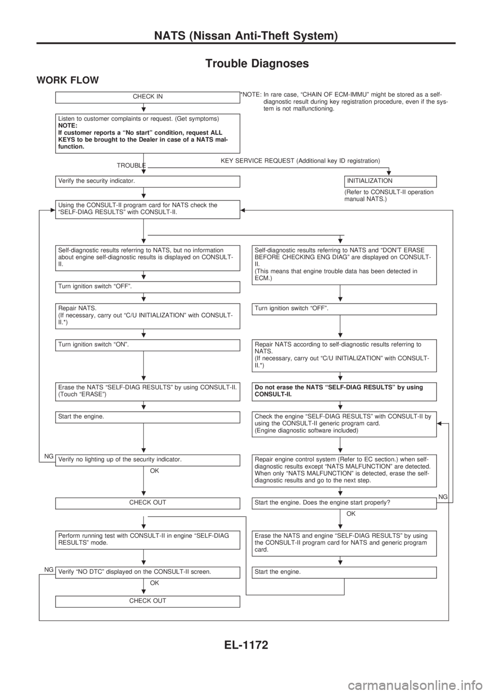
WORK FLOW
CHECK IN*NOTE: In rare case, ªCHAIN OF ECM-IMMUº might be stored as a self-
diagnostic result during key registration procedure, even if the sys-
tem is not malfunctioning.
Listen to customer complaints or request. (Get symptoms)
NOTE:
If customer reports a ªNo startº condition, request ALL
KEYS to be brought to the Dealer in case of a NATS mal-
function.
TROUBLEKEY SERVICE REQUEST (Additional key ID registration).Verify the security indicator.INITIALIZATION
(Refer to CONSULT-II operation
manual NATS.)
cUsing the CONSULT-II program card for NATS check the
ªSELF-DIAG RESULTSº with CONSULT-II.b
Self-diagnostic results referring to NATS, but no information
about engine self-diagnostic results is displayed on CONSULT-
II.Self-diagnostic results referring to NATS and ªDON'T ERASE
BEFORE CHECKING ENG DIAGº are displayed on CONSULT-
II.
(This means that engine trouble data has been detected in
ECM.)
Turn ignition switch ªOFFº.
Repair NATS.
(If necessary, carry out ªC/U INITIALIZATIONº with CONSULT-
II.*)Turn ignition switch ªOFFº.
Turn ignition switch ªONº.Repair NATS according to self-diagnostic results referring to
NATS.
(If necessary, carry out ªC/U INITIALIZATIONº with CONSULT-
II.*)
Erase the NATS ªSELF-DIAG RESULTSº by using CONSULT-II.
(Touch ªERASEº)Do not erase the NATS ªSELF-DIAG RESULTSº by using
CONSULT-II.
Start the engine.Check the engine ªSELF-DIAG RESULTSº with CONSULT-II by
using the CONSULT-II generic program card.
(Engine diagnostic software included)b
NGVerify no lighting up of the security indicator.
OKRepair engine control system (Refer to EC section.) when self-
diagnostic results except ªNATS MALFUNCTIONº are detected.
When only ªNATS MALFUNCTIONº is detected, erase the self-
diagnostic results and go to the next step.
CHECK OUTStart the engine. Does the engine start properly?
OKNG
Perform running test with CONSULT-II in engine ªSELF-DIAG
RESULTSº mode.Erase the NATS and engine ªSELF-DIAG RESULTSº by using
the CONSULT-II program card for NATS and generic program
card.
NGVerify ªNO DTCº displayed on the CONSULT-II screen.
OKStart the engine.
CHECK OUT
.
.
.
..
.
..
..
..
..
..
..
..
..
.
NATS (Nissan Anti-Theft System)
EL-1172
Page 683 of 1033
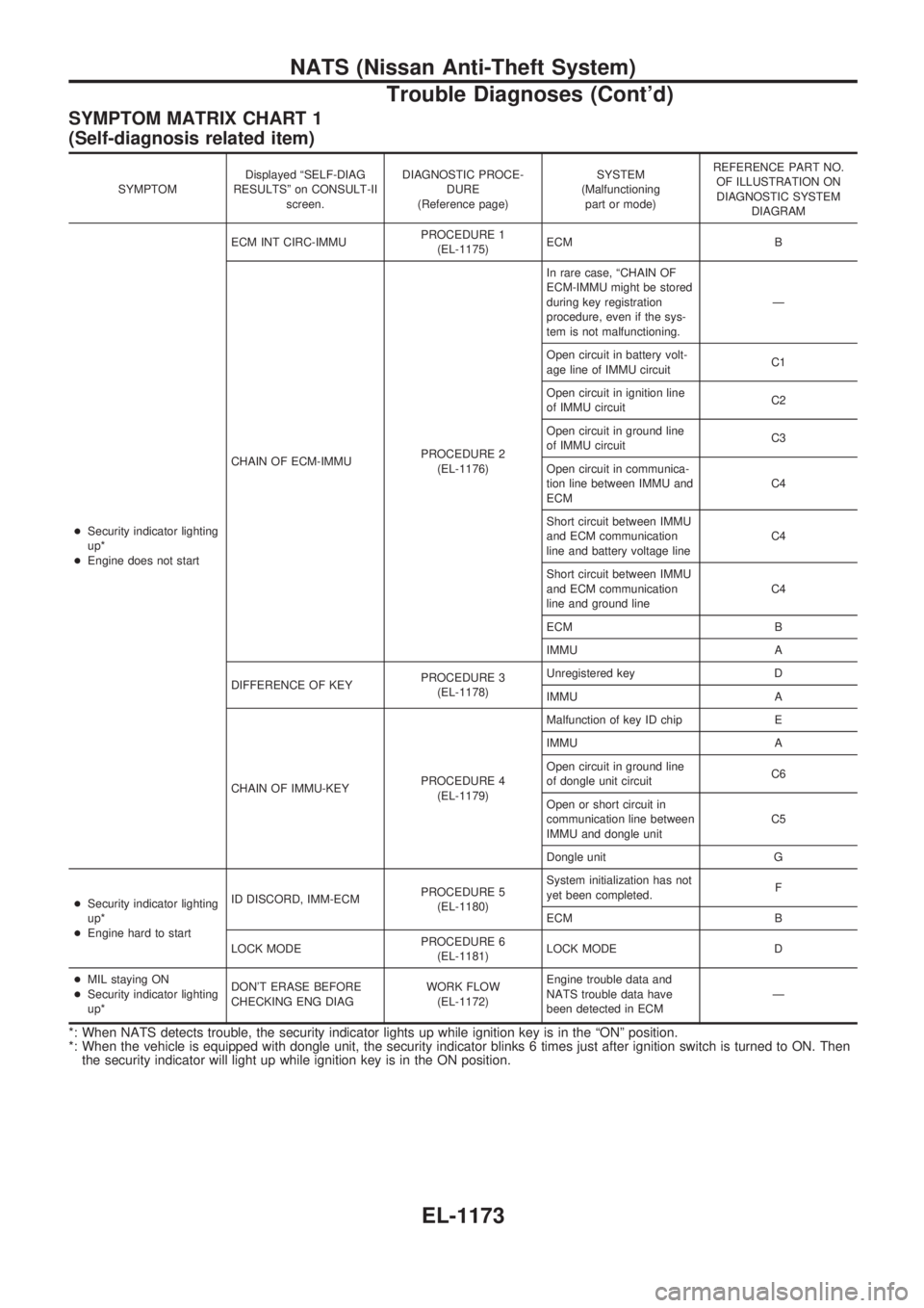
SYMPTOM MATRIX CHART 1
(Self-diagnosis related item)
SYMPTOMDisplayed ªSELF-DIAG
RESULTSº on CONSULT-II
screen.DIAGNOSTIC PROCE-
DURE
(Reference page)SYSTEM
(Malfunctioning
part or mode)REFERENCE PART NO.
OF ILLUSTRATION ON
DIAGNOSTIC SYSTEM
DIAGRAM
+Security indicator lighting
up*
+Engine does not startECM INT CIRC-IMMUPROCEDURE 1
(EL-1175)ECM B
CHAIN OF ECM-IMMUPROCEDURE 2
(EL-1176)In rare case, ªCHAIN OF
ECM-IMMU might be stored
during key registration
procedure, even if the sys-
tem is not malfunctioning.Ð
Open circuit in battery volt-
age line of IMMU circuitC1
Open circuit in ignition line
of IMMU circuitC2
Open circuit in ground line
of IMMU circuitC3
Open circuit in communica-
tion line between IMMU and
ECMC4
Short circuit between IMMU
and ECM communication
line and battery voltage lineC4
Short circuit between IMMU
and ECM communication
line and ground lineC4
ECM B
IMMU A
DIFFERENCE OF KEYPROCEDURE 3
(EL-1178)Unregistered key D
IMMU A
CHAIN OF IMMU-KEYPROCEDURE 4
(EL-1179)Malfunction of key ID chip E
IMMU A
Open circuit in ground line
of dongle unit circuitC6
Open or short circuit in
communication line between
IMMU and dongle unitC5
Dongle unit G
+Security indicator lighting
up*
+Engine hard to startID DISCORD, IMM-ECMPROCEDURE 5
(EL-1180)System initialization has not
yet been completed.F
ECM B
LOCK MODEPROCEDURE 6
(EL-1181)LOCK MODE D
+MIL staying ON
+Security indicator lighting
up*DON'T ERASE BEFORE
CHECKING ENG DIAGWORK FLOW
(EL-1172)Engine trouble data and
NATS trouble data have
been detected in ECMÐ
*: When NATS detects trouble, the security indicator lights up while ignition key is in the ªONº position.
*: When the vehicle is equipped with dongle unit, the security indicator blinks 6 times just after ignition switch is turned to ON. Then
the security indicator will light up while ignition key is in the ON position.
NATS (Nissan Anti-Theft System)
Trouble Diagnoses (Cont'd)
EL-1173
Page 684 of 1033
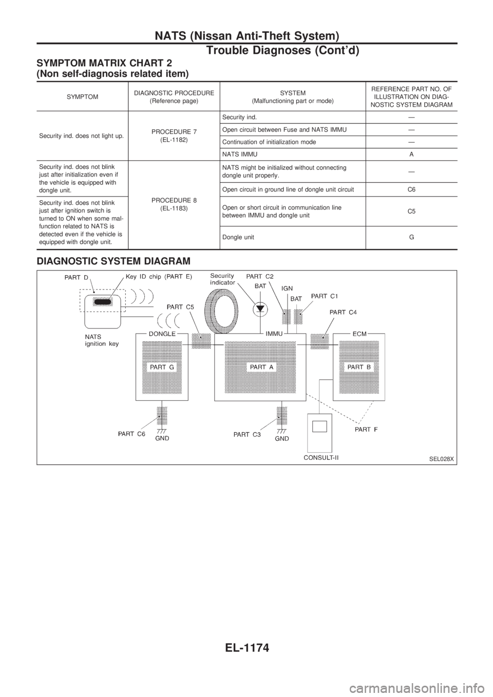
SYMPTOM MATRIX CHART 2
(Non self-diagnosis related item)
SYMPTOMDIAGNOSTIC PROCEDURE
(Reference page)SYSTEM
(Malfunctioning part or mode)REFERENCE PART NO. OF
ILLUSTRATION ON DIAG-
NOSTIC SYSTEM DIAGRAM
Security ind. does not light up.PROCEDURE 7
(EL-1182)Security ind. Ð
Open circuit between Fuse and NATS IMMU Ð
Continuation of initialization mode Ð
NATS IMMU A
Security ind. does not blink
just after initialization even if
the vehicle is equipped with
dongle unit.
PROCEDURE 8
(EL-1183)NATS might be initialized without connecting
dongle unit properly.Ð
Open circuit in ground line of dongle unit circuit C6
Security ind. does not blink
just after ignition switch is
turned to ON when some mal-
function related to NATS is
detected even if the vehicle is
equipped with dongle unit.Open or short circuit in communication line
between IMMU and dongle unitC5
Dongle unit G
DIAGNOSTIC SYSTEM DIAGRAM
SEL028X
NATS (Nissan Anti-Theft System)
Trouble Diagnoses (Cont'd)
EL-1174
Page 692 of 1033
![NISSAN PATROL 2000 Electronic Repair Manual DIAGNOSTIC PROCEDURE 7
ªSECURITY IND. DOES NOT LIGHT UPº
Check 7.5A fuse [No.24, located in the
fuse block (J/B)].
OK
cNG
Replace fuse.
NATS INITIALIZATION
1) Install the 7.5A fuse.
2) Perform initi NISSAN PATROL 2000 Electronic Repair Manual DIAGNOSTIC PROCEDURE 7
ªSECURITY IND. DOES NOT LIGHT UPº
Check 7.5A fuse [No.24, located in the
fuse block (J/B)].
OK
cNG
Replace fuse.
NATS INITIALIZATION
1) Install the 7.5A fuse.
2) Perform initi](/manual-img/5/57367/w960_57367-691.png)
DIAGNOSTIC PROCEDURE 7
ªSECURITY IND. DOES NOT LIGHT UPº
Check 7.5A fuse [No.24, located in the
fuse block (J/B)].
OK
cNG
Replace fuse.
NATS INITIALIZATION
1) Install the 7.5A fuse.
2) Perform initialization with CON-
SULT-II.
For the operation of
initialization, refer to ªCON-
SULT-II operation manual
NATSº.
Turn ignition switch ªOFFº.
Start engine and turn ignition switch
ªOFFº.
Check the security ind. lighting.
NG
cOK
END
Check voltage between security ind. con-
nector terminal
V1and ground.
Voltage: Battery voltage
OK
cNG
Check harness for open or
short between fuse and
security ind.
CHECK INDICATOR LAMP.
OK
cNG
Repair harness.
CHECK NATS IMMU FUNCTION.
1. Connect NATS IMMU connector.
2. Disconnect security ind. connector.
3. Check continuity between NATS IMMU
terminal
V6and ground.
Continuity should exist intermit-
tently.
OK
cNG
NATS IMMU is malfunc-
tioning. Replace IMMU.
Perform initializa-
tion with CON-
SULT-II.
For the operation
of initialization,
refer to ªCON-
SULT-II operation
manual NATSº.
Check harness for open or short between
security indicator and NATS IMMU.
SEL931UA
SEL164X
.
.
.
.
.
.
.
.
.
NATS (Nissan Anti-Theft System)
Trouble Diagnoses (Cont'd)
EL-1182
Page 770 of 1033
3. Remove injection tube and injection nozzle assembly. Refer
to EC section, ªInjection Tube and Injection Nozzleº in
ªBASIC SERVICE PROCEDUREº.
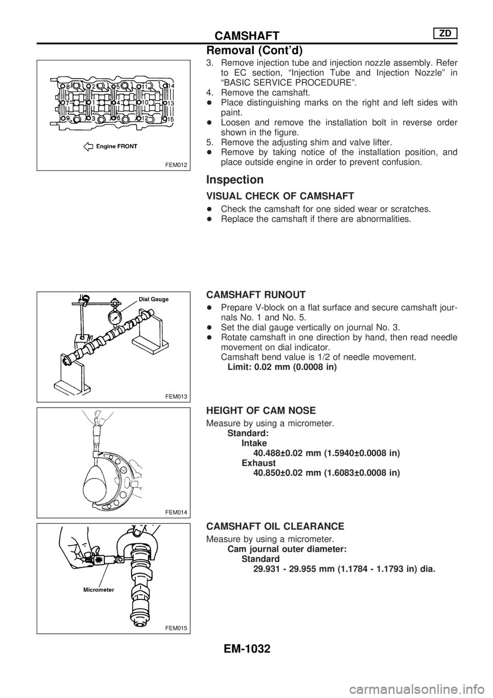
4. Remove the camshaft.
+Place distinguishing marks on the right and left sides with
paint.
+Loosen and remove the installation bolt in reverse order
shown in the figure.
5. Remove the adjusting shim and valve lifter.
+Remove by taking notice of the installation position, and
place outside engine in order to prevent confusion.
Inspection
VISUAL CHECK OF CAMSHAFT
+Check the camshaft for one sided wear or scratches.
+Replace the camshaft if there are abnormalities.
CAMSHAFT RUNOUT
+Prepare V-block on a flat surface and secure camshaft jour-
nals No. 1 and No. 5.
+Set the dial gauge vertically on journal No. 3.
+Rotate camshaft in one direction by hand, then read needle
movement on dial indicator.
Camshaft bend value is 1/2 of needle movement.
Limit: 0.02 mm (0.0008 in)
HEIGHT OF CAM NOSE
Measure by using a micrometer.
Standard:
Intake
40.488 0.02 mm (1.5940 0.0008 in)
Exhaust
40.850 0.02 mm (1.6083 0.0008 in)
CAMSHAFT OIL CLEARANCE
Measure by using a micrometer.
Cam journal outer diameter:
Standard
29.931 - 29.955 mm (1.1784 - 1.1793 in) dia.
FEM012
FEM013
FEM014
FEM015
CAMSHAFTZD
Removal (Cont'd)
EM-1032
Page 775 of 1033
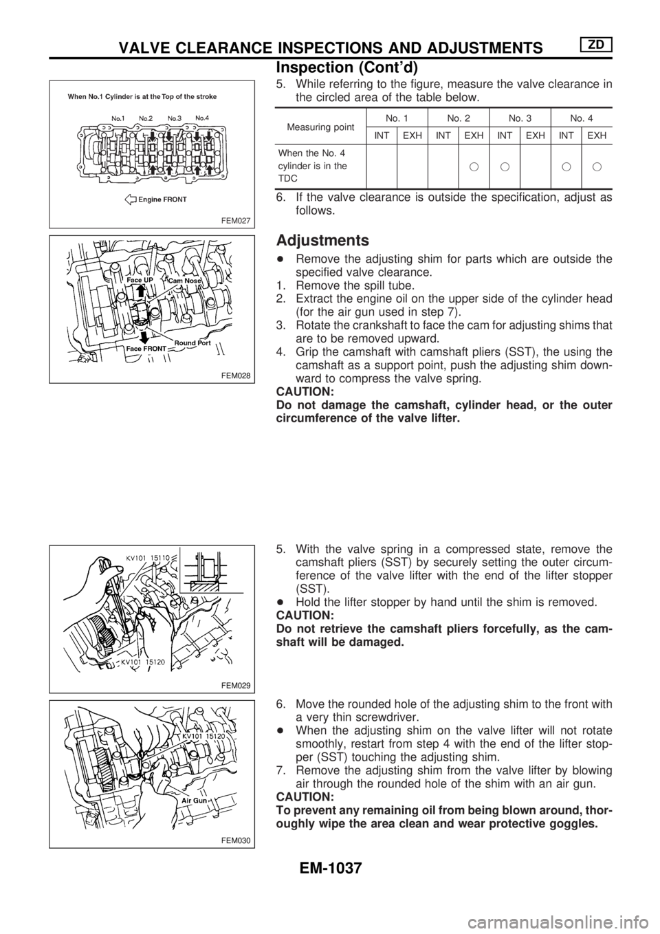
5. While referring to the figure, measure the valve clearance in
the circled area of the table below.
Measuring pointNo. 1 No. 2 No. 3 No. 4
INT EXH INT EXH INT EXH INT EXH
When the No. 4
cylinder is in the
TDCjj jj
6. If the valve clearance is outside the specification, adjust as
follows.
Adjustments
+Remove the adjusting shim for parts which are outside the
specified valve clearance.
1. Remove the spill tube.
2. Extract the engine oil on the upper side of the cylinder head
(for the air gun used in step 7).
3. Rotate the crankshaft to face the cam for adjusting shims that
are to be removed upward.
4. Grip the camshaft with camshaft pliers (SST), the using the
camshaft as a support point, push the adjusting shim down-
ward to compress the valve spring.
CAUTION:
Do not damage the camshaft, cylinder head, or the outer
circumference of the valve lifter.
5. With the valve spring in a compressed state, remove the
camshaft pliers (SST) by securely setting the outer circum-
ference of the valve lifter with the end of the lifter stopper
(SST).
+Hold the lifter stopper by hand until the shim is removed.
CAUTION:
Do not retrieve the camshaft pliers forcefully, as the cam-
shaft will be damaged.
6. Move the rounded hole of the adjusting shim to the front with
a very thin screwdriver.
+When the adjusting shim on the valve lifter will not rotate
smoothly, restart from step 4 with the end of the lifter stop-
per (SST) touching the adjusting shim.
7. Remove the adjusting shim from the valve lifter by blowing
air through the rounded hole of the shim with an air gun.
CAUTION:
To prevent any remaining oil from being blown around, thor-
oughly wipe the area clean and wear protective goggles.
FEM027
FEM028
FEM029
FEM030
VALVE CLEARANCE INSPECTIONS AND ADJUSTMENTSZD
Inspection (Cont'd)
EM-1037
Page 803 of 1033
5. Disconnect harness connectors from alternator and air com-
pressor.
6. Remove alternator.
7. After removing refrigerant, remove pipes of air compressor
and inlet/outlet.
8. Disconnect heating hose, install blank cap to hose to prevent
coolant from leaking.
9. Remove heating pipe.
10. Remove heat insulator.
11. Remove catalytic converter.
Engine room (Right)
12. Remove power steering reservoir tank from bracket, and fix
it to the vehicle with a rope.
CAUTION:
Keep the reservoir tank level when fixing to prevent oil leak.
13. Remove fuel feed and return hoses.
CAUTION:
Install blank caps immediately to avoid fuel leakage.
14. Remove all harness connectors on the engine, and move
harnesses to the side of the vehicle.
Vehicle underfloor
15. Remove starter motor.
16. Detach A/T oil cooler pipes from oil pan. (A/T model)
17. Remove rear propeller shaft.
18. Remove mounting bolts to secure the engine to transmission.
1) Remove torque converter installation bolt. (A/T model)
2) Lift transmission bottom with transmission jack, and remove
rear mount members from the vehicle.
3) Lower transmission with the jack, and remove upper mount-
ing bolts securing the engine to transmission.
4) Lift transmission with the jack, and reinstall rear mount mem-
bers to the vehicle.
5) Position the jack to the front side of transmission.
6) Remove remaining mounting bolts securing the engine to
transmission.
Removal operation
19. Remove air conditioner high pressure pipes at the rear of the
engine room.
+This is due to some inconvenience in the rear slinger instal-
lation.
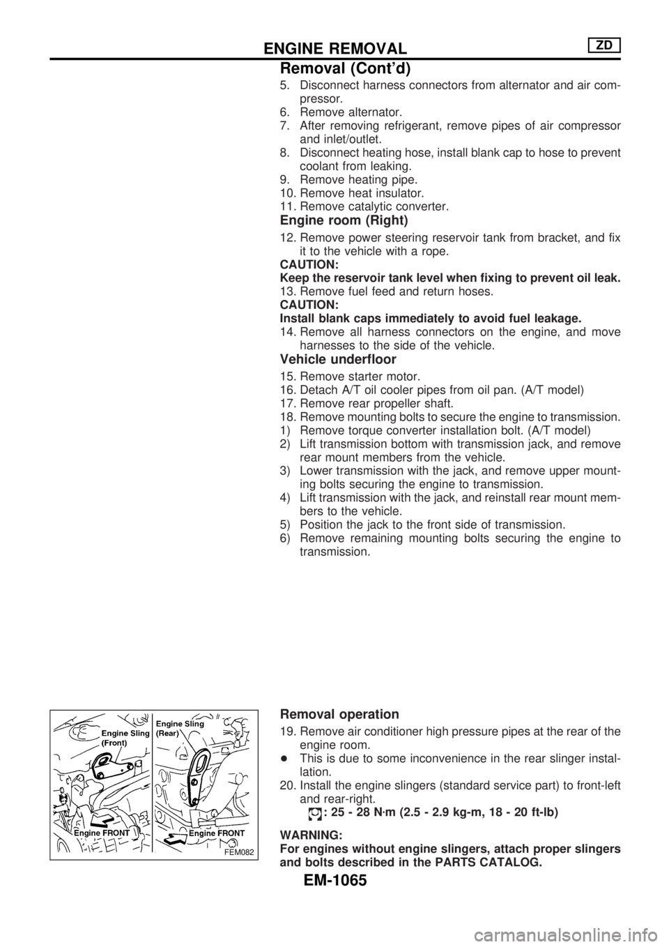
20. Install the engine slingers (standard service part) to front-left
and rear-right.
:25-28Nzm (2.5 - 2.9 kg-m, 18 - 20 ft-lb)
WARNING:
For engines without engine slingers, attach proper slingers
and bolts described in the PARTS CATALOG.
FEM082
ENGINE REMOVALZD
Removal (Cont'd)
EM-1065
Page 804 of 1033
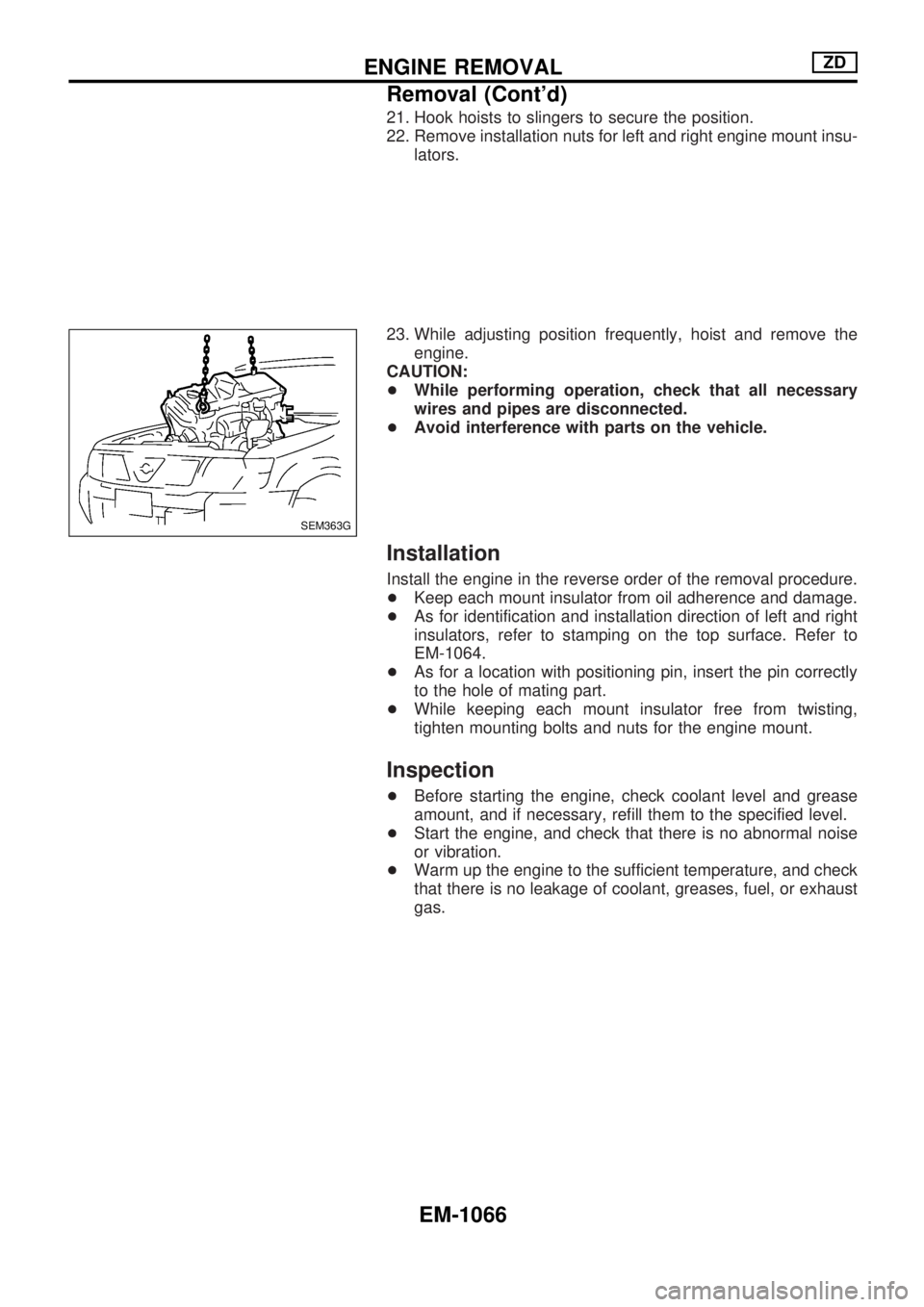
21. Hook hoists to slingers to secure the position.
22. Remove installation nuts for left and right engine mount insu-
lators.
23. While adjusting position frequently, hoist and remove the
engine.
CAUTION:
+While performing operation, check that all necessary
wires and pipes are disconnected.
+Avoid interference with parts on the vehicle.
Installation
Install the engine in the reverse order of the removal procedure.
+Keep each mount insulator from oil adherence and damage.
+As for identification and installation direction of left and right
insulators, refer to stamping on the top surface. Refer to
EM-1064.
+As for a location with positioning pin, insert the pin correctly
to the hole of mating part.
+While keeping each mount insulator free from twisting,
tighten mounting bolts and nuts for the engine mount.
Inspection
+Before starting the engine, check coolant level and grease
amount, and if necessary, refill them to the specified level.
+Start the engine, and check that there is no abnormal noise
or vibration.
+Warm up the engine to the sufficient temperature, and check
that there is no leakage of coolant, greases, fuel, or exhaust
gas.
SEM363G
ENGINE REMOVALZD
Removal (Cont'd)
EM-1066