Page 928 of 1033
Installation
lApply sealant as below:
lTighten bolts securing transmission.
Engine BoltsTightening torque
N´m (kg-m, ft-lb)!mm (in)
ZD30DDTi
V1M/T to engine block83 - 113
(8.5 - 11.5, 61 - 83)100 (3.94)
V2M/T to engine oil pan29-39
(3.0 - 4.0, 22 - 29)100 (3.94)
V3Engine oil pan to M/T29-39
(3.0 - 4.0, 22 - 29)70 (2.76)
SMT280D Engine rear plate
Transmission case
Engine block
23.6 (0.929)
23.6 (0.929)
Do not apply sealant
in this range.1) Place
2) Sealant
: Sticked out portion for engine rear plate
from transmission case.
: Mating surface of transmission case and
rear plate.
: Apply genuine anaerobic liquid gasket,
Three Bond TB1207B or TB1207D.
: Apply genuine anaerobic liquid gasket,
Three Bond TB1215 or TB1207D.
Transmission case
Grommet
Engine rear plate Starter Sealant
Rear plate
Unit: mm (in)
SMT324DB ZD30DDTi engine
For starterDowel hole
Dowel hole
(Not used) M/T to engine
Engine to M/T
REMOVAL AND INSTALLATIONFS5R50B
MT-1008
Page 939 of 1033
4. Remove counter gear rear snap ring.
5. Remove lock plate of reverse idler shaft and then remove
reverse idler gear, washers, reverse idler needle bearings
and reverse idler shaft.
6. Pull out the following parts.
lOD counter gear
lOD synchronizer assembly with OD shift fork and OD fork
rod
7. Pull out OD gear bushing and thrust washer.
8. Remove bolts securing bearing retainer and then remove
bearing retainer.
9. Pull out OD main gear.
SMT265B
SMT863A
SMT266B Puller
SMT279D Mainshaft
OD gear bushing
Bearing retainer
Rear
SMT268B Puller
DISASSEMBLYFS5R50B
Gear Components (Cont'd)
MT-1019
Page 940 of 1033
10. Remove mainshaft bearing snap ring.
11. Pull out mainshaft bearing.
12. Support mainshaft with hoist.
13. Remove bolts securing front cover and then remove front
cover.
14. Remove counter gear front bearing outer race.
lTap rear end of counter gear lightly before removing
bearing.
15. Remove counter gear rear bearing outer race.
lTap front end of counter gear lightly before removing
bearing.
16. Settle counter gear assembly down on bottom of transmis-
sion case.
17. Remove main drive gear assembly.
lSet cutting portion of clutch gear on main drive gear to
upper side.
SMT281D Mainshaft bearing
Puller Rear
SMT319D Rear
SMT282D
SMT283D (Outer race)
Counter gear rear bearing
(Inner race)
SMT284D Upper
Rear view
Front
DISASSEMBLYFS5R50B
Gear Components (Cont'd)
MT-1020
Page 977 of 1033

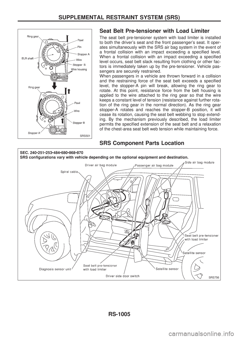
Seat Belt Pre-tensioner with Load Limiter
The seat belt pre-tensioner system with load limiter is installed
to both the driver's seat and the front passenger's seat. It oper-
ates simultaneously with the SRS air bag system in the event of
a frontal collision with an impact exceeding a specified level.
When a frontal collision with an impact exceeding a specified
level occurs, seat belt slack resulting from clothing or other fac-
tors is immediately taken up by the pre-tensioner. Vehicle pas-
sengers are securely restrained.
When passengers in a vehicle are thrown forward in a collision
and the restraining force of the seat belt exceeds a specified
level, the stopper-A pin will break, allowing the ring gear to
rotate. At this point, resistance force from the belt housing is
applied to the wire attached to the ring gear so that the wire
keeps a constant level of tension (resistance against further rota-
tion of the ring gear in the normal direction). As the ring gear
stopper-A rotates and reaches the stopper-B position, it will
cease its rotation, causing the seat belt webbing to stop extend-
ing. By the mechanism previously described, the load limiter
permits the specified extension of the seat belt and a relaxation
of the chest-area seat belt web tension while maintaining force.
SRS Component Parts Location
SRS501
SRS756
SUPPLEMENTAL RESTRAINT SYSTEM (SRS)
RS-1005
Page 984 of 1033

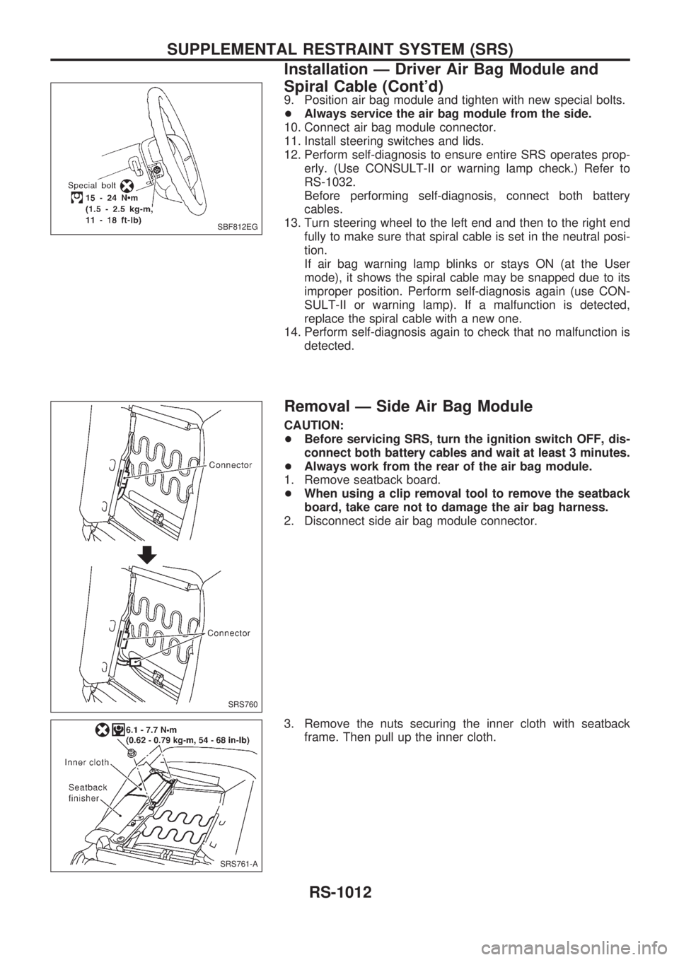
9. Position air bag module and tighten with new special bolts.
+Always service the air bag module from the side.
10. Connect air bag module connector.
11. Install steering switches and lids.
12. Perform self-diagnosis to ensure entire SRS operates prop-
erly. (Use CONSULT-II or warning lamp check.) Refer to
RS-1032.
Before performing self-diagnosis, connect both battery
cables.
13. Turn steering wheel to the left end and then to the right end
fully to make sure that spiral cable is set in the neutral posi-
tion.
If air bag warning lamp blinks or stays ON (at the User
mode), it shows the spiral cable may be snapped due to its
improper position. Perform self-diagnosis again (use CON-
SULT-II or warning lamp). If a malfunction is detected,
replace the spiral cable with a new one.
14. Perform self-diagnosis again to check that no malfunction is
detected.
Removal Ð Side Air Bag Module
CAUTION:
+Before servicing SRS, turn the ignition switch OFF, dis-
connect both battery cables and wait at least 3 minutes.
+Always work from the rear of the air bag module.
1. Remove seatback board.
+When using a clip removal tool to remove the seatback
board, take care not to damage the air bag harness.
2. Disconnect side air bag module connector.
3. Remove the nuts securing the inner cloth with seatback
frame. Then pull up the inner cloth.
SBF812EG
SRS760
SRS761-A
SUPPLEMENTAL RESTRAINT SYSTEM (SRS)
Installation Ð Driver Air Bag Module and
Spiral Cable (Cont'd)
RS-1012
Page 985 of 1033

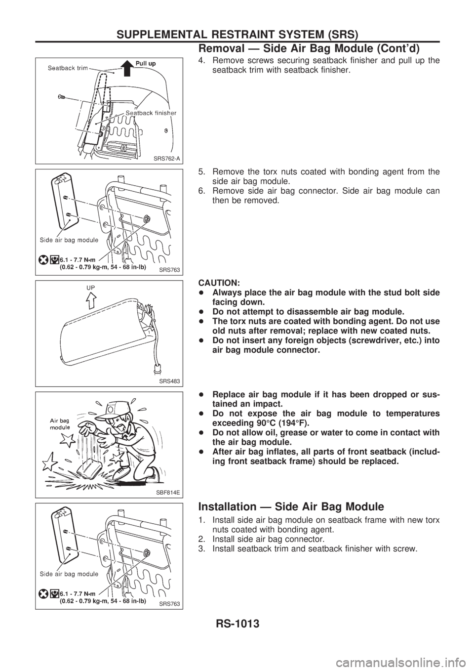
4. Remove screws securing seatback finisher and pull up the
seatback trim with seatback finisher.
5. Remove the torx nuts coated with bonding agent from the
side air bag module.
6. Remove side air bag connector. Side air bag module can
then be removed.
CAUTION:
+Always place the air bag module with the stud bolt side
facing down.
+Do not attempt to disassemble air bag module.
+The torx nuts are coated with bonding agent. Do not use
old nuts after removal; replace with new coated nuts.
+Do not insert any foreign objects (screwdriver, etc.) into
air bag module connector.
+Replace air bag module if it has been dropped or sus-
tained an impact.
+Do not expose the air bag module to temperatures
exceeding 90ÉC (194ÉF).
+Do not allow oil, grease or water to come in contact with
the air bag module.
+After air bag inflates, all parts of front seatback (includ-
ing front seatback frame) should be replaced.
Installation Ð Side Air Bag Module
1. Install side air bag module on seatback frame with new torx
nuts coated with bonding agent.
2. Install side air bag connector.
3. Install seatback trim and seatback finisher with screw.
SRS762-A
SRS763
SRS483
SBF814E
SRS763
SUPPLEMENTAL RESTRAINT SYSTEM (SRS)
Removal Ð Side Air Bag Module (Cont'd)
RS-1013
Page 986 of 1033
4. Secure the inner cloth which covers the side air bag module
with nuts.
5. Connect side air bag module connector.
6. Install seatback board with new clips.
7. Connect both battery cables.
8. Go to ªSelf-diagnosisº, RS-1032 and perform self-diagnosis
to
ensure entire SRS operates properly. (Use CONSULT-II or
air bag warning lamp.)
SRS764-A
SRS765
SUPPLEMENTAL RESTRAINT SYSTEM (SRS)
Installation Ð Side Air Bag Module (Cont'd)
RS-1014
Page 988 of 1033

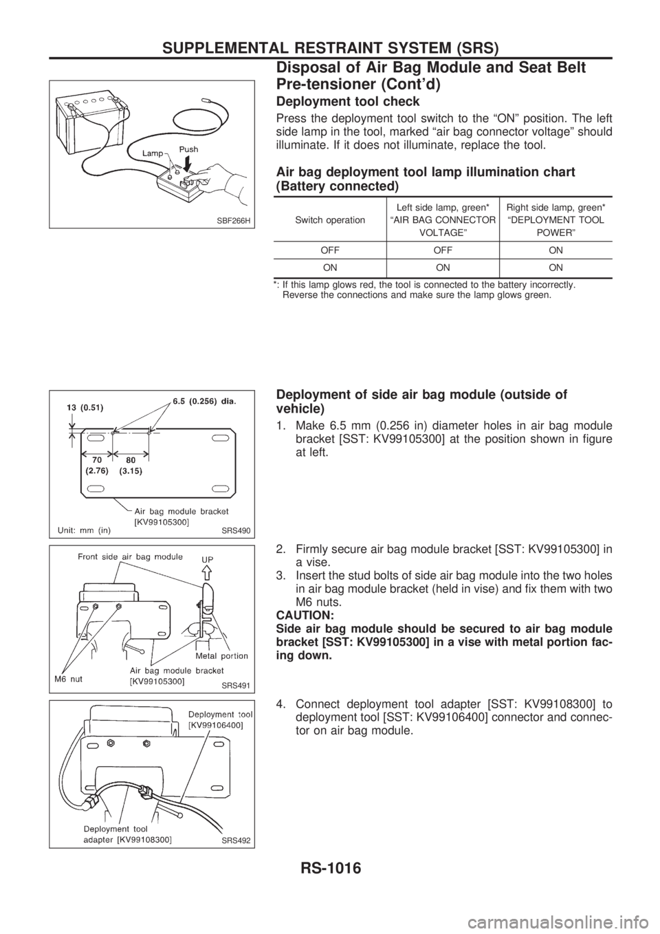
Deployment tool check
Press the deployment tool switch to the ªONº position. The left
side lamp in the tool, marked ªair bag connector voltageº should
illuminate. If it does not illuminate, replace the tool.
Air bag deployment tool lamp illumination chart
(Battery connected)
Switch operationLeft side lamp, green*
ªAIR BAG CONNECTOR
VOLTAGEºRight side lamp, green*
ªDEPLOYMENT TOOL
POWERº
OFF OFF ON
ON ON ON
*: If this lamp glows red, the tool is connected to the battery incorrectly.
Reverse the connections and make sure the lamp glows green.
Deployment of side air bag module (outside of
vehicle)
1. Make 6.5 mm (0.256 in) diameter holes in air bag module
bracket [SST: KV99105300] at the position shown in figure
at left.
2. Firmly secure air bag module bracket [SST: KV99105300] in
a vise.
3. Insert the stud bolts of side air bag module into the two holes
in air bag module bracket (held in vise) and fix them with two
M6 nuts.
CAUTION:
Side air bag module should be secured to air bag module
bracket [SST: KV99105300] in a vise with metal portion fac-
ing down.
4. Connect deployment tool adapter [SST: KV99108300] to
deployment tool [SST: KV99106400] connector and connec-
tor on air bag module.
SBF266H
SRS490
SRS491
SRS492
SUPPLEMENTAL RESTRAINT SYSTEM (SRS)
Disposal of Air Bag Module and Seat Belt
Pre-tensioner (Cont'd)
RS-1016