2000 NISSAN PATROL ECU
[x] Cancel search: ECUPage 806 of 1033
Selection Procedure for Selective Part
Combination
Location Selective part combination Item Method
Cylinder block - pistonPiston and piston assembly
(Part No. is given to a piston
and piston pin as a set.)Piston grade (Piston outer
diameter)Refer to ªSelective combination
chartº.
+Identification grade stamped on each part represents initial
dimension of new part. This grade will not be applied to a
reused part.
+Measure correct dimensions of a reused or modified part,
then refer to ªSelective combination chartº in this manual to
identify the grade.
+Refer to the applicable pages for measurement method for
each part, standards for reuse, and selecting method for
selective part combination.
Disassembly
1. Remove engine assembly from vehicle.
Refer to EM-1064, ªENGINE REMOVALº.
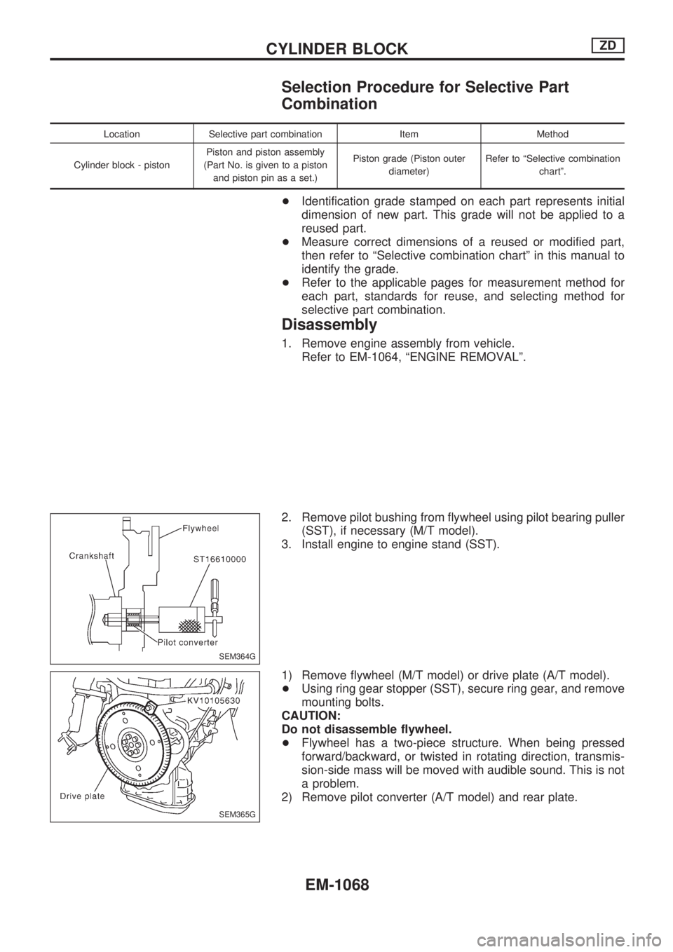
2. Remove pilot bushing from flywheel using pilot bearing puller
(SST), if necessary (M/T model).
3. Install engine to engine stand (SST).
1) Remove flywheel (M/T model) or drive plate (A/T model).
+Using ring gear stopper (SST), secure ring gear, and remove
mounting bolts.
CAUTION:
Do not disassemble flywheel.
+Flywheel has a two-piece structure. When being pressed
forward/backward, or twisted in rotating direction, transmis-
sion-side mass will be moved with audible sound. This is not
a problem.
2) Remove pilot converter (A/T model) and rear plate.
SEM364G
SEM365G
CYLINDER BLOCKZD
EM-1068
Page 819 of 1033
Assembly
1. Blow air sufficiently to inside coolant passage, oil passage,
crankcase, and cylinder bore to remove foreign matter.
2. Install main bearings and thrust bearings.
1) Remove contamination, dust and oil from bearing mounting
positions on cylinder block and main bearing caps.
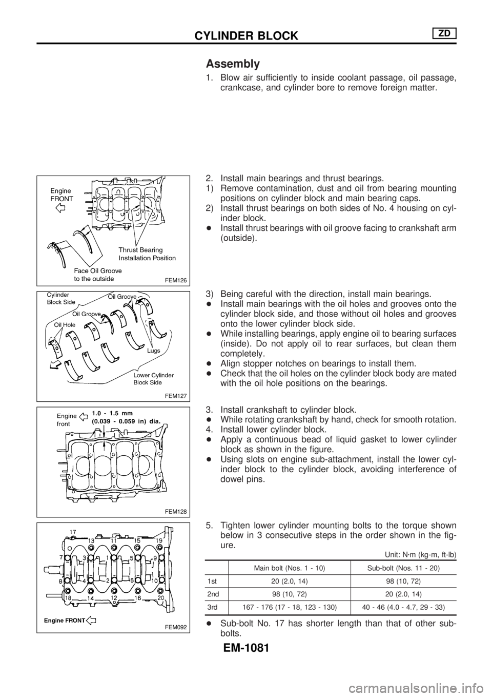
2) Install thrust bearings on both sides of No. 4 housing on cyl-
inder block.
+Install thrust bearings with oil groove facing to crankshaft arm
(outside).
3) Being careful with the direction, install main bearings.
+Install main bearings with the oil holes and grooves onto the
cylinder block side, and those without oil holes and grooves
onto the lower cylinder block side.
+While installing bearings, apply engine oil to bearing surfaces
(inside). Do not apply oil to rear surfaces, but clean them
completely.
+Align stopper notches on bearings to install them.
+Check that the oil holes on the cylinder block body are mated
with the oil hole positions on the bearings.
3. Install crankshaft to cylinder block.
+While rotating crankshaft by hand, check for smooth rotation.
4. Install lower cylinder block.
+Apply a continuous bead of liquid gasket to lower cylinder
block as shown in the figure.
+Using slots on engine sub-attachment, install the lower cyl-
inder block to the cylinder block, avoiding interference of
dowel pins.
5. Tighten lower cylinder mounting bolts to the torque shown
below in 3 consecutive steps in the order shown in the fig-
ure.
Unit: Nzm (kg-m, ft-lb)
Main bolt (Nos. 1 - 10) Sub-bolt (Nos. 11 - 20)
1st 20 (2.0, 14) 98 (10, 72)
2nd 98 (10, 72) 20 (2.0, 14)
3rd 167 - 176 (17 - 18, 123 - 130) 40 - 46 (4.0 - 4.7, 29 - 33)
+Sub-bolt No. 17 has shorter length than that of other sub-
bolts.
FEM126
FEM127
FEM128
FEM092
CYLINDER BLOCKZD
EM-1081
Page 822 of 1033
15. Install removed parts to engine in the reverse order of disas-
sembly.
16. Remove engine from engine stand.
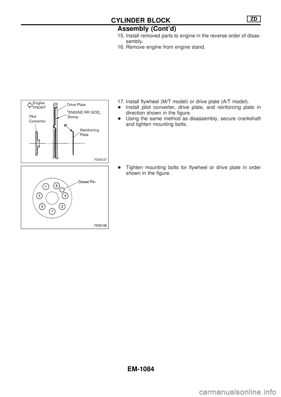
17. Install flywheel (M/T model) or drive plate (A/T model).
+Install pilot converter, drive plate, and reinforcing plate in
direction shown in the figure.
+Using the same method as disassembly, secure crankshaft
and tighten mounting bolts.
+Tighten mounting bolts for flywheel or drive plate in order
shown in the figure.
FEM137
FEM138
CYLINDER BLOCKZD
Assembly (Cont'd)
EM-1084
Page 848 of 1033
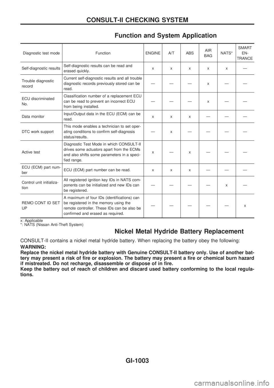
Function and System Application
Diagnostic test mode Function ENGINE A/T ABSAIR
BAGNATS*SMART
EN-
TRANCE
Self-diagnostic resultsSelf-diagnostic results can be read and
erased quickly.xxxxxÐ
Trouble diagnostic
recordCurrent self-diagnostic results and all trouble
diagnostic records previously stored can be
read.ÐÐÐxÐÐ
ECU discriminated
No.Classification number of a replacement ECU
can be read to prevent an incorrect ECU
from being installed.ÐÐÐxÐÐ
Data monitorInput/Output data in the ECU (ECM) can be
read.xxxÐÐÐ
DTC work supportThis mode enables a technician to set oper-
ating conditions to confirm self-diagnosis
status/results.Ð x ÐÐÐÐ
Active testDiagnostic Test Mode in which CONSULT-II
drives some actuators apart from the ECMs
and also shifts some parameters in a speci-
fied range.xÐxÐÐÐ
ECU (ECM) part num-
berECU (ECM) part number can be read. x x x Ð Ð Ð
Control unit initializa-
tionAll registered ignition key IDs in NATS com-
ponents can be initialized and new IDs can
be registered.ÐÐÐÐ x Ð
REMO CONT ID SET
UPA maximum of four IDs (identifications) can
be registered in the memory using the
remote controller. These IDs can be also be
confirmed and erased as required.ÐÐÐÐÐ x
x: Applicable
*: NATS (Nissan Anti-Theft System)
Nickel Metal Hydride Battery Replacement
CONSULT-II contains a nickel metal hydride battery. When replacing the battery obey the following:
WARNING:
Replace the nickel metal hydride battery with Genuine CONSULT-II battery only. Use of another bat-
tery may present a risk of fire or explosion. The battery may present a fire or chemical burn hazard
if mistreated. Do not recharge, disassemble or dispose of in fire.
Keep the battery out of reach of children and discard used battery conforming to the local regula-
tions.
CONSULT-II CHECKING SYSTEM
GI-1003
Page 893 of 1033
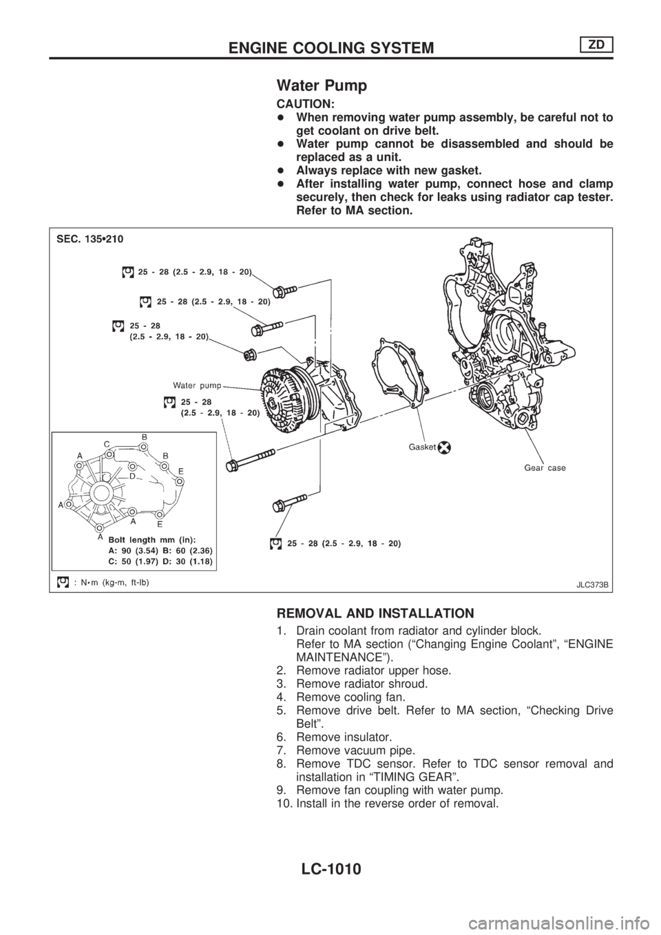
Water Pump
CAUTION:
+When removing water pump assembly, be careful not to
get coolant on drive belt.
+Water pump cannot be disassembled and should be
replaced as a unit.
+Always replace with new gasket.
+After installing water pump, connect hose and clamp
securely, then check for leaks using radiator cap tester.
Refer to MA section.
REMOVAL AND INSTALLATION
1. Drain coolant from radiator and cylinder block.
Refer to MA section (ªChanging Engine Coolantº, ªENGINE
MAINTENANCEº).
2. Remove radiator upper hose.
3. Remove radiator shroud.
4. Remove cooling fan.
5. Remove drive belt. Refer to MA section, ªChecking Drive
Beltº.
6. Remove insulator.
7. Remove vacuum pipe.
8. Remove TDC sensor. Refer to TDC sensor removal and
installation in ªTIMING GEARº.
9. Remove fan coupling with water pump.
10. Install in the reverse order of removal.
JLC373B
ENGINE COOLING SYSTEMZD
LC-1010
Page 910 of 1033
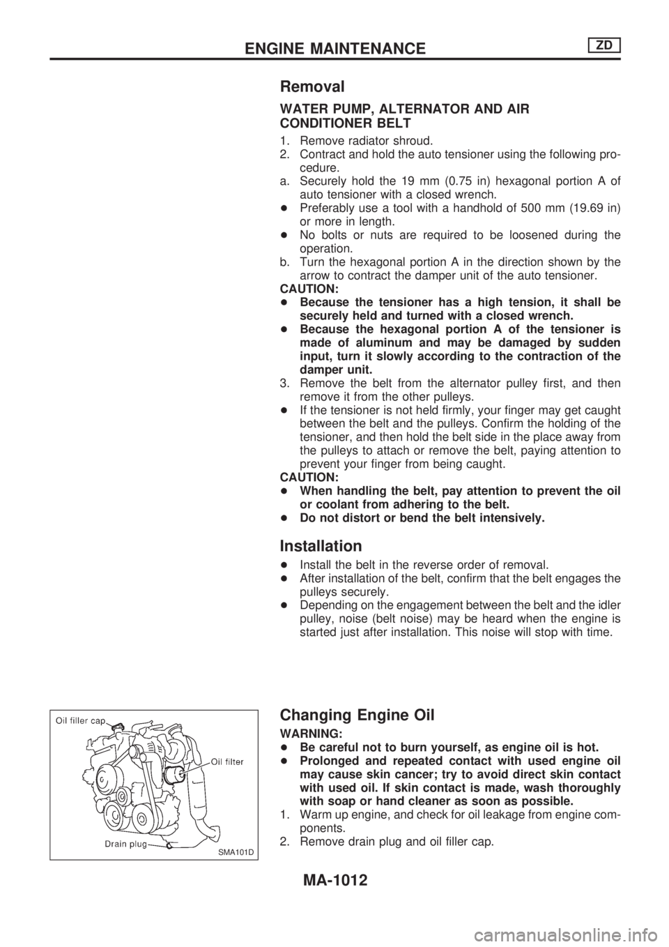
Removal
WATER PUMP, ALTERNATOR AND AIR
CONDITIONER BELT
1. Remove radiator shroud.
2. Contract and hold the auto tensioner using the following pro-
cedure.
a. Securely hold the 19 mm (0.75 in) hexagonal portion A of
auto tensioner with a closed wrench.
+Preferably use a tool with a handhold of 500 mm (19.69 in)
or more in length.
+No bolts or nuts are required to be loosened during the
operation.
b. Turn the hexagonal portion A in the direction shown by the
arrow to contract the damper unit of the auto tensioner.
CAUTION:
+Because the tensioner has a high tension, it shall be
securely held and turned with a closed wrench.
+Because the hexagonal portion A of the tensioner is
made of aluminum and may be damaged by sudden
input, turn it slowly according to the contraction of the
damper unit.
3. Remove the belt from the alternator pulley first, and then
remove it from the other pulleys.
+If the tensioner is not held firmly, your finger may get caught
between the belt and the pulleys. Confirm the holding of the
tensioner, and then hold the belt side in the place away from
the pulleys to attach or remove the belt, paying attention to
prevent your finger from being caught.
CAUTION:
+When handling the belt, pay attention to prevent the oil
or coolant from adhering to the belt.
+Do not distort or bend the belt intensively.
Installation
+Install the belt in the reverse order of removal.
+After installation of the belt, confirm that the belt engages the
pulleys securely.
+Depending on the engagement between the belt and the idler
pulley, noise (belt noise) may be heard when the engine is
started just after installation. This noise will stop with time.
Changing Engine Oil
WARNING:
+Be careful not to burn yourself, as engine oil is hot.
+Prolonged and repeated contact with used engine oil
may cause skin cancer; try to avoid direct skin contact
with used oil. If skin contact is made, wash thoroughly
with soap or hand cleaner as soon as possible.
1. Warm up engine, and check for oil leakage from engine com-
ponents.
2. Remove drain plug and oil filler cap.
SMA101D
ENGINE MAINTENANCEZD
MA-1012
Page 912 of 1033
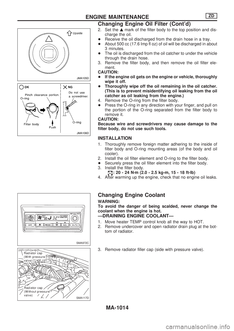
2. Set themmark of the filter body to the top position and dis-
charge the oil.
+Receive the oil discharged from the drain hose in a tray.
+About 500 cc (17.6 Imp fl oz) of oil will be discharged in about
3 minutes.
+The oil is discharged from the oil catcher to under the vehicle
through the drain hose.
3. Remove the filter body, and then remove the oil filter ele-
ment.
CAUTION:
+If the engine oil gets on the engine or vehicle, thoroughly
wipe it off.
+Thoroughly wipe off the oil remaining in the oil catcher.
(This is to prevent misidentifying oil leaking from the oil
catcher as oil leaking from the engine.)
4. Remove the O-ring from the filter body.
+Press the O-ring in any direction with your finger, and pull on
the portion of the O-ring separated from the filter body to
remove it.
CAUTION:
Because wire and screwdrivers may cause damage to the
filter body, do not use such tools.
INSTALLATION
1. Thoroughly remove foreign matter adhering to the inside of
filter body and O-ring mounting areas (of the body and oil
cooler).
2. Install the oil filter element and O-ring to the filter body.
+Securely press the oil filter element into the filter body.
3. Install the filter body.
:20-24Nzm (2.0 - 2.5 kg-m, 15 - 18 ft-lb)
4. After warming up the engine, check that no engine oil leaks.
Changing Engine Coolant
WARNING:
To avoid the danger of being scalded, never change the
coolant when the engine is hot.
ÐDRAINING ENGINE COOLANTÐ
1. Move heater TEMP control knob all the way to HOT.
2. Remove undercover and open radiator drain plug at the bot-
tom of radiator.
3. Remove radiator filler cap (side with pressure valve).
JMA105D
JMA106D
SMA972C
SMA117D
ENGINE MAINTENANCEZD
Changing Engine Oil Filter (Cont'd)
MA-1014
Page 918 of 1033
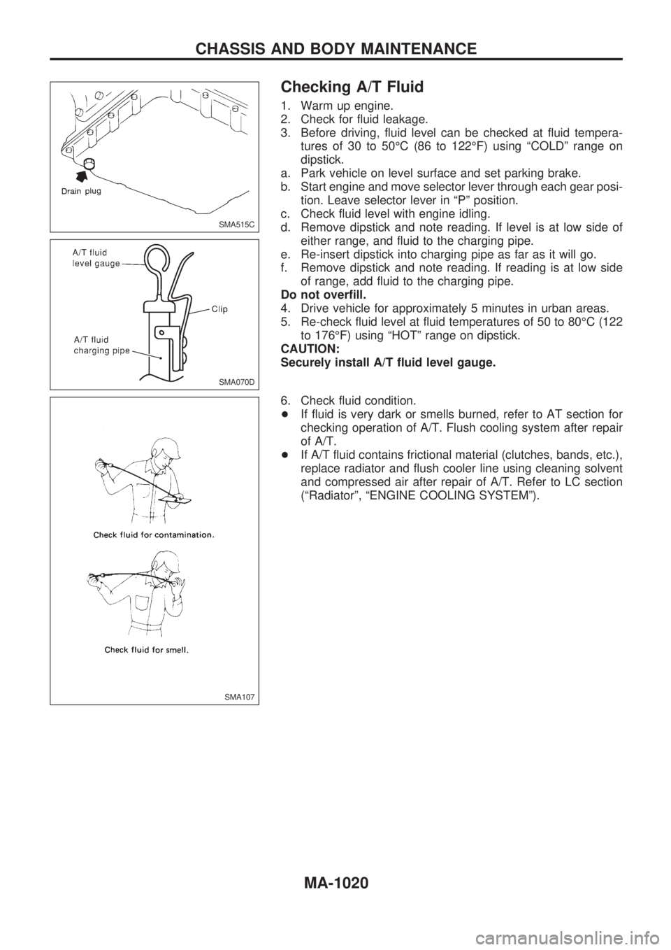
Checking A/T Fluid
1. Warm up engine.
2. Check for fluid leakage.
3. Before driving, fluid level can be checked at fluid tempera-
tures of 30 to 50ÉC (86 to 122ÉF) using ªCOLDº range on
dipstick.
a. Park vehicle on level surface and set parking brake.
b. Start engine and move selector lever through each gear posi-
tion. Leave selector lever in ªPº position.
c. Check fluid level with engine idling.
d. Remove dipstick and note reading. If level is at low side of
either range, and fluid to the charging pipe.
e. Re-insert dipstick into charging pipe as far as it will go.
f. Remove dipstick and note reading. If reading is at low side
of range, add fluid to the charging pipe.
Do not overfill.
4. Drive vehicle for approximately 5 minutes in urban areas.
5. Re-check fluid level at fluid temperatures of 50 to 80ÉC (122
to 176ÉF) using ªHOTº range on dipstick.
CAUTION:
Securely install A/T fluid level gauge.
6. Check fluid condition.
+If fluid is very dark or smells burned, refer to AT section for
checking operation of A/T. Flush cooling system after repair
of A/T.
+If A/T fluid contains frictional material (clutches, bands, etc.),
replace radiator and flush cooler line using cleaning solvent
and compressed air after repair of A/T. Refer to LC section
(ªRadiatorº, ªENGINE COOLING SYSTEMº).
SMA515C
SMA070D
SMA107
CHASSIS AND BODY MAINTENANCE
MA-1020