2000 NISSAN PATROL battery
[x] Cancel search: batteryPage 659 of 1033
System Description
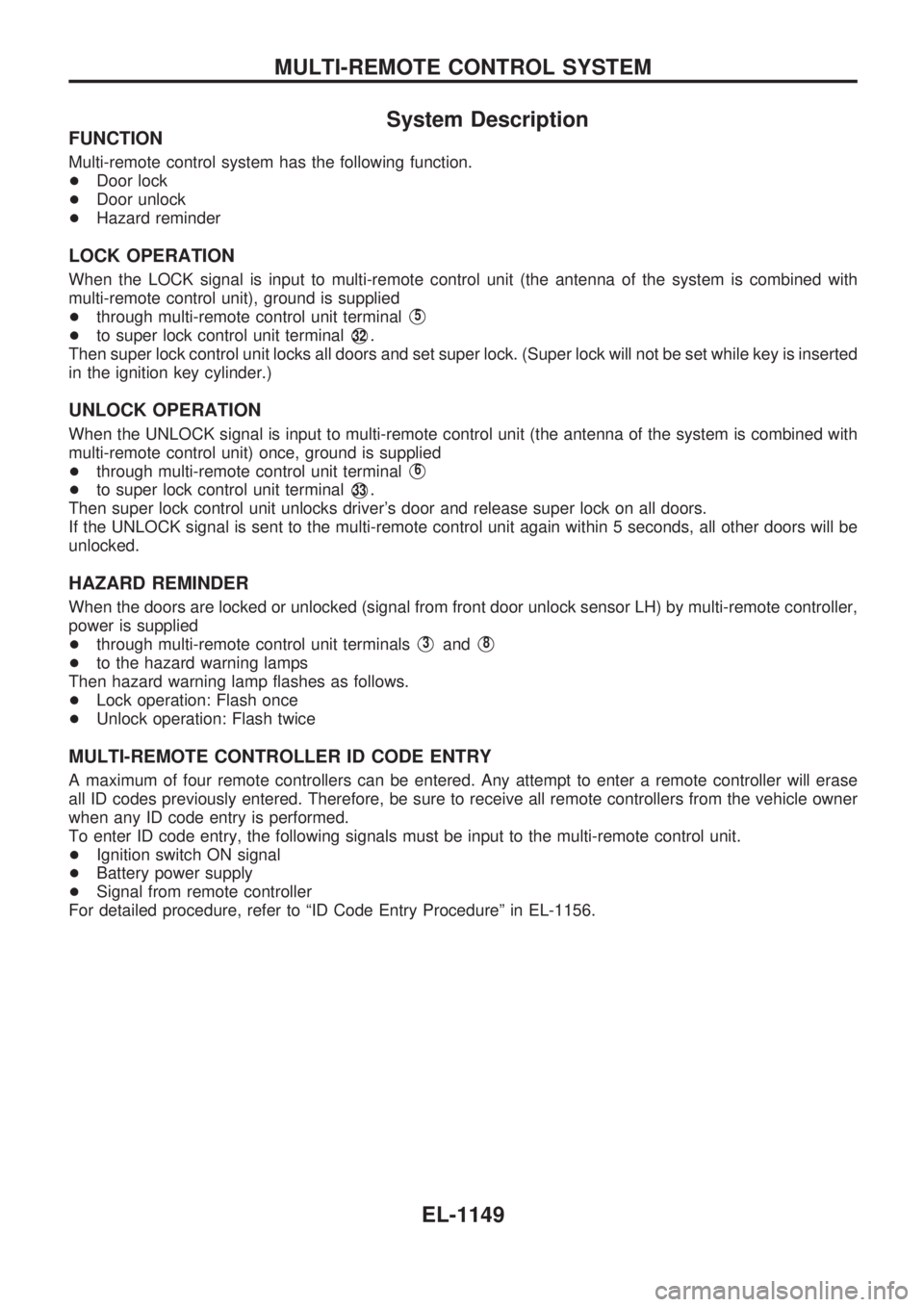
FUNCTION
Multi-remote control system has the following function.
+Door lock
+Door unlock
+Hazard reminder
LOCK OPERATION
When the LOCK signal is input to multi-remote control unit (the antenna of the system is combined with
multi-remote control unit), ground is supplied
+through multi-remote control unit terminal
V5
+to super lock control unit terminalV32.
Then super lock control unit locks all doors and set super lock. (Super lock will not be set while key is inserted
in the ignition key cylinder.)
UNLOCK OPERATION
When the UNLOCK signal is input to multi-remote control unit (the antenna of the system is combined with
multi-remote control unit) once, ground is supplied
+through multi-remote control unit terminal
V6
+to super lock control unit terminalV33.
Then super lock control unit unlocks driver's door and release super lock on all doors.
If the UNLOCK signal is sent to the multi-remote control unit again within 5 seconds, all other doors will be
unlocked.
HAZARD REMINDER
When the doors are locked or unlocked (signal from front door unlock sensor LH) by multi-remote controller,
power is supplied
+through multi-remote control unit terminals
V3andV8
+to the hazard warning lamps
Then hazard warning lamp flashes as follows.
+Lock operation: Flash once
+Unlock operation: Flash twice
MULTI-REMOTE CONTROLLER ID CODE ENTRY
A maximum of four remote controllers can be entered. Any attempt to enter a remote controller will erase
all ID codes previously entered. Therefore, be sure to receive all remote controllers from the vehicle owner
when any ID code entry is performed.
To enter ID code entry, the following signals must be input to the multi-remote control unit.
+Ignition switch ON signal
+Battery power supply
+Signal from remote controller
For detailed procedure, refer to ªID Code Entry Procedureº in EL-1156.
MULTI-REMOTE CONTROL SYSTEM
EL-1149
Page 664 of 1033
Trouble Diagnoses
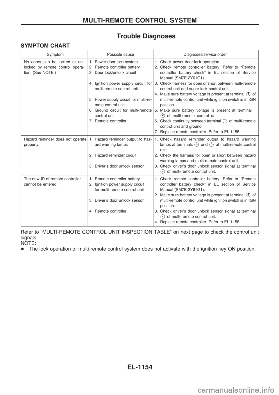
SYMPTOM CHART
Symptom Possible cause Diagnoses/service order
No doors can be locked or un-
locked by remote control opera-
tion. (See NOTE.)1. Power door lock system
2. Remote controller battery
3. Door lock/unlock circuit
4. Ignition power supply circuit for
multi-remote control unit
5. Power supply circuit for multi-re-
mote control unit
6. Ground circuit for multi-remote
control unit
7. Remote controller1. Check power door lock operation.
2. Check remote controller battery. Refer to ªRemote
controller battery checkº in EL section of Service
Manual (SM7E-2Y61G1).
3. Check harness for open or short between multi-remote
control unit and super lock control unit.
4. Make sure battery voltage is present at terminal
V4of
multi-remote control unit while ignition switch is in IGN
position.
5. Make sure battery voltage is present at terminal
V2of multi-remote control unit.
6. Check continuity between terminal
V1of multi-remote
control unit and ground.
7. Replace remote controller. Refer to EL-1156.
Hazard reminder does not operate
properly.1. Hazard reminder output to haz-
ard warning lamps
2. Hazard reminder circuit
3. Driver's door unlock sensor1. Check hazard reminder output to hazard warning
lamps at terminals
V3andV8of multi-remote control
unit.
2. Check the harness for open or short between hazard
warning lamps and multi-remote control unit.
3. Check driver's door unlock sensor signal at terminal
V7of multi-remote control unit.
The new ID of remote controller
cannot be entered.1. Remote controller battery
2. Ignition power supply circuit
for multi-remote control unit
3. Driver's door unlock sensor
4. Remote controller1. Check remote controller battery. Refer to ªRemote
controller battery checkº in EL section of Service
Manual (SM7E-2Y61G1).
2. Make sure battery voltage is present at terminal
V4of
multi-remote control unit while ignition switch is in IGN
position.
3. Check driver's door unlock sensor signal at terminal
V7of multi-remote control unit.
4. Replace remote controller. Refer to EL-1156.
Refer to ªMULTI-REMOTE CONTROL UNIT INSPECTION TABLEº on next page to check the control unit
signals.
NOTE:
+The lock operation of multi-remote control system does not activate with the ignition key ON position.
MULTI-REMOTE CONTROL SYSTEM
EL-1154
Page 666 of 1033
ID Code Entry Procedure
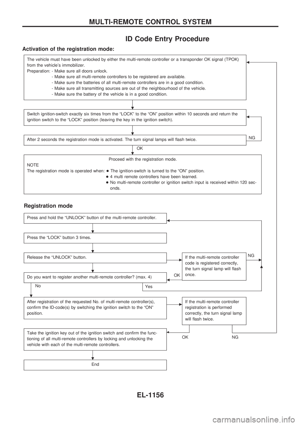
Activation of the registration mode:
The vehicle must have been unlocked by either the multi-remote controller or a transponder OK signal (TPOK)
from the vehicle's immobilizer.
Preparation: - Make sure all doors unlock.
- Make sure all multi-remote controllers to be registered are available.
- Make sure the batteries of all multi-remote controllers are in a good condition.
- Make sure all transmitting sources are out of the neighbourhood of the vehicle.
- Make sure the battery of the vehicle is in a good condition.b
Switch ignition-switch exactly six times from the ªLOCKº to the ªONº position within 10 seconds and return the
ignition switch to the ªLOCKº position (leaving the key in the ignition switch).b
After 2 seconds the registration mode is activated. The turn signal lamps will flash twice.
OKNG
Proceed with the registration mode.
NOTE
The registration mode is operated when:+The ignition-switch is turned to the ªONº position.
+4 multi remote controllers have been learned.
+No multi-remote controller or ignition switch input is received within 120 sec-
onds.
Registration mode
Press and hold the ªUNLOCKº button of the multi-remote controller.b
Press the ªLOCKº button 3 times.
Release the ªUNLOCKº button.cIf the multi-remote controller
code is registered correctly,
the turn signal lamp will flash
once.cNG
Do you want to register another multi-remote controller? (max. 4)
No
Yes
bOK
m
After registration of the requested No. of multi-remote controller(s),
confirm the ID-code(s) by switching the ignition switch to the ªONº
position.cIf the multi-remote controller
registration is performed
correctly, the turn signal lamp
will flash twice.
Take the ignition key out of the ignition switch and confirm the func-
tioning of all multi-remote controllers by locking and unlocking the
vehicle with each of the multi-remote controllers.b
OKNG
End
.
.
.
.
.
.
.
.
MULTI-REMOTE CONTROL SYSTEM
EL-1156
Page 667 of 1033
Remote Controller Battery Replacement
SEL241X
MULTI-REMOTE CONTROL SYSTEM
EL-1157
Page 683 of 1033
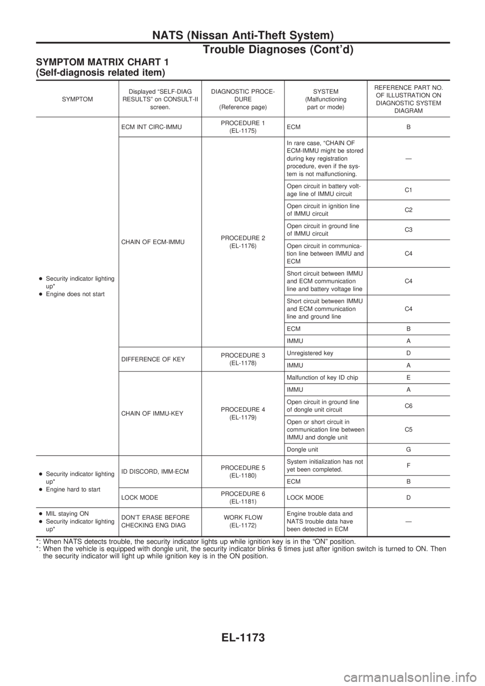
SYMPTOM MATRIX CHART 1
(Self-diagnosis related item)
SYMPTOMDisplayed ªSELF-DIAG
RESULTSº on CONSULT-II
screen.DIAGNOSTIC PROCE-
DURE
(Reference page)SYSTEM
(Malfunctioning
part or mode)REFERENCE PART NO.
OF ILLUSTRATION ON
DIAGNOSTIC SYSTEM
DIAGRAM
+Security indicator lighting
up*
+Engine does not startECM INT CIRC-IMMUPROCEDURE 1
(EL-1175)ECM B
CHAIN OF ECM-IMMUPROCEDURE 2
(EL-1176)In rare case, ªCHAIN OF
ECM-IMMU might be stored
during key registration
procedure, even if the sys-
tem is not malfunctioning.Ð
Open circuit in battery volt-
age line of IMMU circuitC1
Open circuit in ignition line
of IMMU circuitC2
Open circuit in ground line
of IMMU circuitC3
Open circuit in communica-
tion line between IMMU and
ECMC4
Short circuit between IMMU
and ECM communication
line and battery voltage lineC4
Short circuit between IMMU
and ECM communication
line and ground lineC4
ECM B
IMMU A
DIFFERENCE OF KEYPROCEDURE 3
(EL-1178)Unregistered key D
IMMU A
CHAIN OF IMMU-KEYPROCEDURE 4
(EL-1179)Malfunction of key ID chip E
IMMU A
Open circuit in ground line
of dongle unit circuitC6
Open or short circuit in
communication line between
IMMU and dongle unitC5
Dongle unit G
+Security indicator lighting
up*
+Engine hard to startID DISCORD, IMM-ECMPROCEDURE 5
(EL-1180)System initialization has not
yet been completed.F
ECM B
LOCK MODEPROCEDURE 6
(EL-1181)LOCK MODE D
+MIL staying ON
+Security indicator lighting
up*DON'T ERASE BEFORE
CHECKING ENG DIAGWORK FLOW
(EL-1172)Engine trouble data and
NATS trouble data have
been detected in ECMÐ
*: When NATS detects trouble, the security indicator lights up while ignition key is in the ªONº position.
*: When the vehicle is equipped with dongle unit, the security indicator blinks 6 times just after ignition switch is turned to ON. Then
the security indicator will light up while ignition key is in the ON position.
NATS (Nissan Anti-Theft System)
Trouble Diagnoses (Cont'd)
EL-1173
Page 686 of 1033
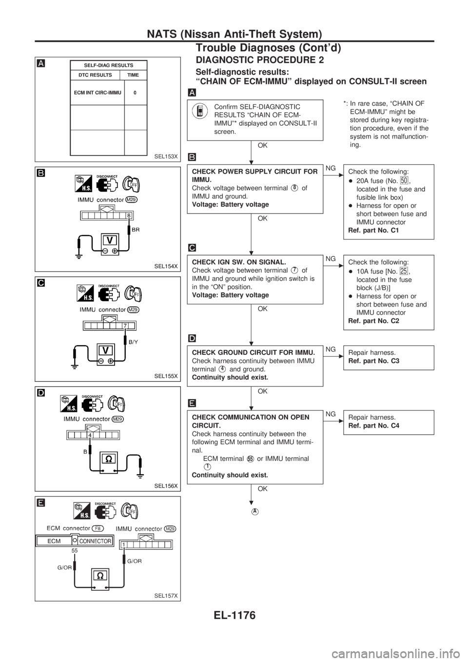
DIAGNOSTIC PROCEDURE 2
Self-diagnostic results:
ªCHAIN OF ECM-IMMUº displayed on CONSULT-II screen
Confirm SELF-DIAGNOSTIC
RESULTS ªCHAIN OF ECM-
IMMUº* displayed on CONSULT-II
screen.
OK*: In rare case, ªCHAIN OF
ECM-IMMUº might be
stored during key registra-
tion procedure, even if the
system is not malfunction-
ing.
CHECK POWER SUPPLY CIRCUIT FOR
IMMU.
Check voltage between terminal
V8of
IMMU and ground.
Voltage: Battery voltage
OK
cNG
Check the following:
+20A fuse (No.
50,
located in the fuse and
fusible link box)
+Harness for open or
short between fuse and
IMMU connector
Ref. part No. C1
CHECK IGN SW. ON SIGNAL.
Check voltage between terminal
V7of
IMMU and ground while ignition switch is
in the ªONº position.
Voltage: Battery voltage
OK
cNG
Check the following:
+10A fuse [No.
25,
located in the fuse
block (J/B)]
+Harness for open or
short between fuse and
IMMU connector
Ref. part No. C2
CHECK GROUND CIRCUIT FOR IMMU.
Check harness continuity between IMMU
terminal
V4and ground.
Continuity should exist.
OK
cNG
Repair harness.
Ref. part No. C3
CHECK COMMUNICATION ON OPEN
CIRCUIT.
Check harness continuity between the
following ECM terminal and IMMU termi-
nal.
ECM terminal
V55or IMMU terminal
V1
Continuity should exist.
OK
cNG
Repair harness.
Ref. part No. C4
VA
SEL153X
SEL154X
SEL155X
SEL156X
SEL157X
.
.
.
.
.
NATS (Nissan Anti-Theft System)
Trouble Diagnoses (Cont'd)
EL-1176
Page 692 of 1033
![NISSAN PATROL 2000 Electronic Repair Manual DIAGNOSTIC PROCEDURE 7
ªSECURITY IND. DOES NOT LIGHT UPº
Check 7.5A fuse [No.24, located in the
fuse block (J/B)].
OK
cNG
Replace fuse.
NATS INITIALIZATION
1) Install the 7.5A fuse.
2) Perform initi](/manual-img/5/57367/w960_57367-691.png "NISSAN PATROL 2000 Electronic Repair Manual DIAGNOSTIC PROCEDURE 7
ªSECURITY IND. DOES NOT LIGHT UPº
Check 7.5A fuse [No.24, located in the
fuse block (J/B)].
OK
cNG
Replace fuse.
NATS INITIALIZATION
1) Install the 7.5A fuse.
2) Perform initi")
DIAGNOSTIC PROCEDURE 7
ªSECURITY IND. DOES NOT LIGHT UPº
Check 7.5A fuse [No.24, located in the
fuse block (J/B)].
OK
cNG
Replace fuse.
NATS INITIALIZATION
1) Install the 7.5A fuse.
2) Perform initialization with CON-
SULT-II.
For the operation of
initialization, refer to ªCON-
SULT-II operation manual
NATSº.
Turn ignition switch ªOFFº.
Start engine and turn ignition switch
ªOFFº.
Check the security ind. lighting.
NG
cOK
END
Check voltage between security ind. con-
nector terminal
V1and ground.
Voltage: Battery voltage
OK
cNG
Check harness for open or
short between fuse and
security ind.
CHECK INDICATOR LAMP.
OK
cNG
Repair harness.
CHECK NATS IMMU FUNCTION.
1. Connect NATS IMMU connector.
2. Disconnect security ind. connector.
3. Check continuity between NATS IMMU
terminal
V6and ground.
Continuity should exist intermit-
tently.
OK
cNG
NATS IMMU is malfunc-
tioning. Replace IMMU.
Perform initializa-
tion with CON-
SULT-II.
For the operation
of initialization,
refer to ªCON-
SULT-II operation
manual NATSº.
Check harness for open or short between
security indicator and NATS IMMU.
SEL931UA
SEL164X
.
.
.
.
.
.
.
.
.
NATS (Nissan Anti-Theft System)
Trouble Diagnoses (Cont'd)
EL-1182
Page 748 of 1033
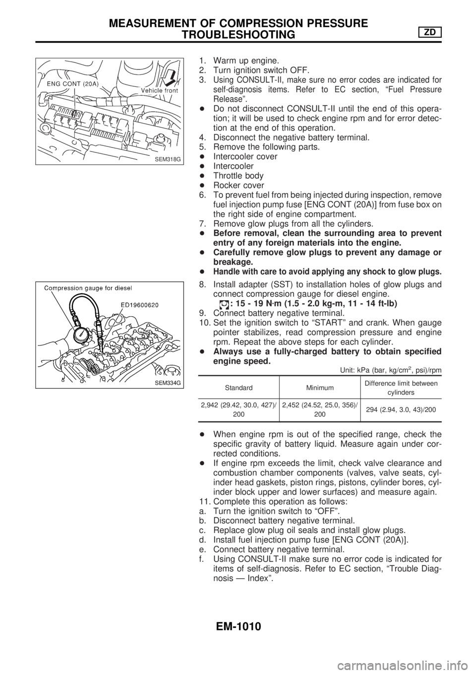
1. Warm up engine.
2. Turn ignition switch OFF.
3.
Using CONSULT-II, make sure no error codes are indicated for
self-diagnosis items. Refer to EC section, ªFuel Pressure
Releaseº.
+Do not disconnect CONSULT-II until the end of this opera-
tion; it will be used to check engine rpm and for error detec-
tion at the end of this operation.
4. Disconnect the negative battery terminal.
5. Remove the following parts.
+Intercooler cover
+Intercooler
+Throttle body
+Rocker cover
6. To prevent fuel from being injected during inspection, remove
fuel injection pump fuse [ENG CONT (20A)] from fuse box on
the right side of engine compartment.
7. Remove glow plugs from all the cylinders.
+Before removal, clean the surrounding area to prevent
entry of any foreign materials into the engine.
+Carefully remove glow plugs to prevent any damage or
breakage.
+
Handle with care to avoid applying any shock to glow plugs.
8. Install adapter (SST) to installation holes of glow plugs and
connect compression gauge for diesel engine.
:15-19Nzm (1.5 - 2.0 kg-m, 11 - 14 ft-lb)
9. Connect battery negative terminal.
10. Set the ignition switch to ªSTARTº and crank. When gauge
pointer stabilizes, read compression pressure and engine
rpm. Repeat the above steps for each cylinder.
+Always use a fully-charged battery to obtain specified
engine speed.
Unit: kPa (bar, kg/cm2, psi)/rpm
Standard MinimumDifference limit between
cylinders
2,942 (29.42, 30.0, 427)/
2002,452 (24.52, 25.0, 356)/
200294 (2.94, 3.0, 43)/200
+When engine rpm is out of the specified range, check the
specific gravity of battery liquid. Measure again under cor-
rected conditions.
+If engine rpm exceeds the limit, check valve clearance and
combustion chamber components (valves, valve seats, cyl-
inder head gaskets, piston rings, pistons, cylinder bores, cyl-
inder block upper and lower surfaces) and measure again.
11. Complete this operation as follows:
a. Turn the ignition switch to ªOFFº.
b. Disconnect battery negative terminal.
c. Replace glow plug oil seals and install glow plugs.
d. Install fuel injection pump fuse [ENG CONT (20A)].
e. Connect battery negative terminal.
f. Using CONSULT-II make sure no error code is indicated for
items of self-diagnosis. Refer to EC section, ªTrouble Diag-
nosis Ð Indexº.
SEM318G
SEM334G
MEASUREMENT OF COMPRESSION PRESSURE
TROUBLESHOOTINGZD
EM-1010