Page 344 of 1033
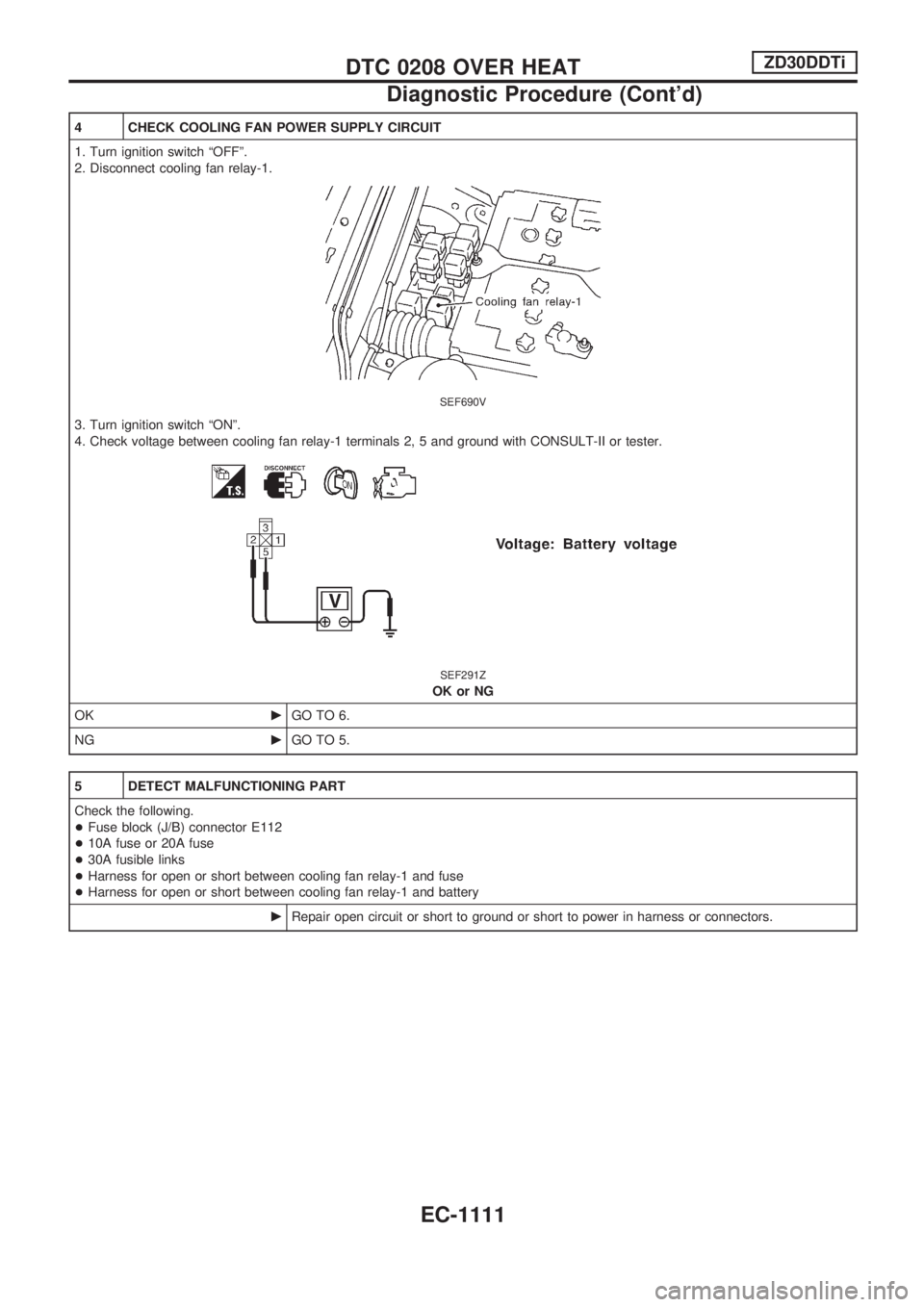
4 CHECK COOLING FAN POWER SUPPLY CIRCUIT
1. Turn ignition switch ªOFFº.
2. Disconnect cooling fan relay-1.
SEF690V
3. Turn ignition switch ªONº.
4. Check voltage between cooling fan relay-1 terminals 2, 5 and ground with CONSULT-II or tester.
SEF291Z
OK or NG
OKcGO TO 6.
NGcGO TO 5.
5 DETECT MALFUNCTIONING PART
Check the following.
+Fuse block (J/B) connector E112
+10A fuse or 20A fuse
+30A fusible links
+Harness for open or short between cooling fan relay-1 and fuse
+Harness for open or short between cooling fan relay-1 and battery
cRepair open circuit or short to ground or short to power in harness or connectors.
DTC 0208 OVER HEATZD30DDTi
Diagnostic Procedure (Cont'd)
EC-1111
Page 346 of 1033
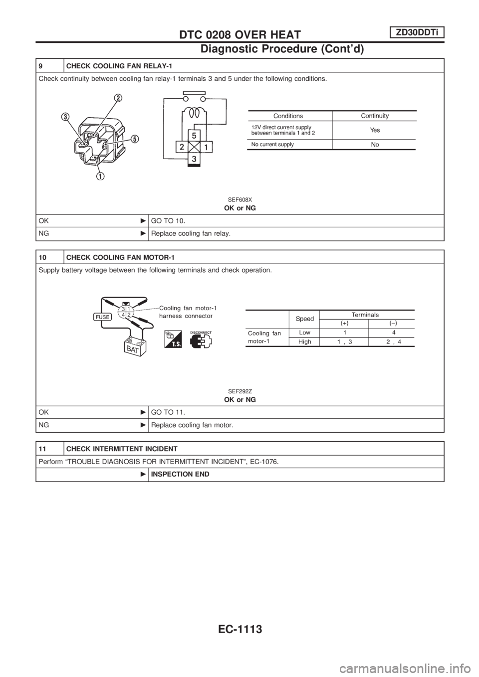
9 CHECK COOLING FAN RELAY-1
Check continuity between cooling fan relay-1 terminals 3 and 5 under the following conditions.
SEF608X
OK or NG
OKcGO TO 10.
NGcReplace cooling fan relay.
10 CHECK COOLING FAN MOTOR-1
Supply battery voltage between the following terminals and check operation.
SEF292Z
OK or NG
OKcGO TO 11.
NGcReplace cooling fan motor.
11 CHECK INTERMITTENT INCIDENT
Perform ªTROUBLE DIAGNOSIS FOR INTERMITTENT INCIDENTº, EC-1076.
cINSPECTION END
DTC 0208 OVER HEATZD30DDTi
Diagnostic Procedure (Cont'd)
EC-1113
Page 359 of 1033
ECM Terminals and Reference Value
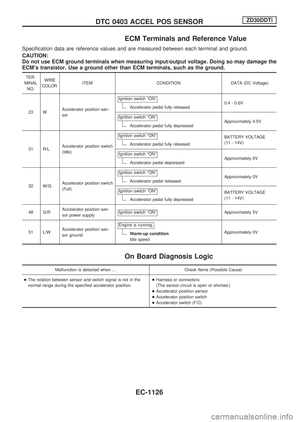
Specification data are reference values and are measured between each terminal and ground.
CAUTION:
Do not use ECM ground terminals when measuring input/output voltage. Doing so may damage the
ECM's transistor. Use a ground other than ECM terminals, such as the ground.
TER-
MINAL
NO.WIRE
COLORITEM CONDITION DATA (DC Voltage)
23 WAccelerator position sen-
sorIgnition switch ªONº
Accelerator pedal fully released0.4 - 0.6V
Ignition switch ªONº
Accelerator pedal fully depressedApproximately 4.5V
31 R/LAccelerator position switch
(Idle)Ignition switch ªONº
Accelerator pedal fully releasedBATTERY VOLTAGE
(11 - 14V)
Ignition switch ªONº
Accelerator pedal depressedApproximately 0V
32 W/GAccelerator position switch
(Full)Ignition switch ªONº
Accelerator pedal releasedApproximately 0V
Ignition switch ªONº
Accelerator pedal fully depressedBATTERY VOLTAGE
(11 - 14V)
48 G/RAccelerator position sen-
sor power supplyIgnition switch ªONº
Approximately 5V
51 L/WAccelerator position sen-
sor groundEngine is running.
Warm-up condition
Idle speedApproximately 0V
On Board Diagnosis Logic
Malfunction is detected when ... Check Items (Possible Cause)
+The relation between sensor and switch signal is not in the
normal range during the specified accelerator position.+Harness or connectors
(The sensor circuit is open or shorted.)
+Accelerator position sensor
+Accelerator position switch
+Accelerator switch (F/C)
DTC 0403 ACCEL POS SENSORZD30DDTi
EC-1126
Page 374 of 1033
On Board Diagnosis Logic
Malfunction is detected when ... Check Items (Possible Cause)
+An improper signal from the sensor is sent to ECM during
engine running and cranking.+Harness or connectors
(The sensor circuit is open.)
+Crankshaft position sensor (TDC)
DTC Confirmation Procedure
Before performing the following procedure, confirm that
battery voltage is more than 10V.
WITH CONSULT-II
1) Turn ignition switch ªONº and select ªDATA MONITORº
mode with CONSULT-II.
2) Crank engine for at least 1 second.
3) Start engine and run it for at least 2 seconds at idle speed.
4) If DTC is detected, go to ªDiagnostic Procedureº, EC-1143.
WITHOUT CONSULT-II
1) Crank engine for at least 1 second.
2) Start engine and run it for at least 2 seconds at idle speed.
3) Turn ignition switch ªOFFº, wait at least 5 seconds and then
turn ªONº.
4) Perform ªDiagnostic Test Mode II (Self-diagnostic results)º
with ECM.
5) If DTC is detected, go to ªDiagnostic Procedureº, EC-1143.
SEF817Y
DTC 0407 CRANK POS SEN (TDC)ZD30DDTi
EC-1141
Page 379 of 1033
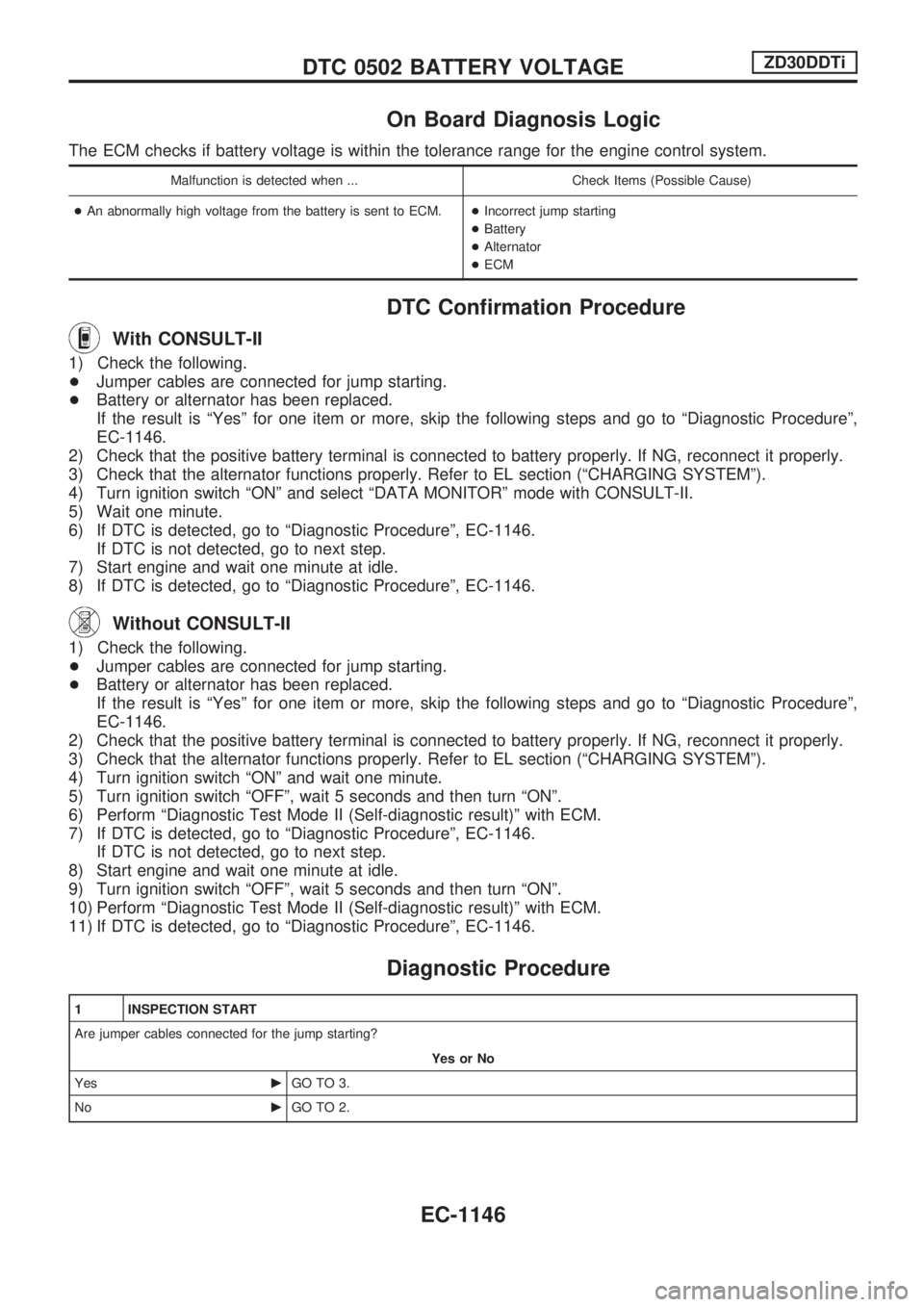
On Board Diagnosis Logic
The ECM checks if battery voltage is within the tolerance range for the engine control system.
Malfunction is detected when ... Check Items (Possible Cause)
+ An abnormally high voltage from the battery is sent to ECM. +Incorrect jump starting
+ Battery
+ Alternator
+ ECM
DTC Confirmation Procedure
With CONSULT-II
1) Checkthefollowing.
+ Jumper cables are connected for jump starting.
+ Battery or alternator has been replaced.
If the result is ªYesº for one item or more, skip the following steps and go to ªDiagnostic Procedureº,
EC-1146.
2) Check that the positive battery terminal is connected to battery properly. If NG, reconnect it properly.
3) Check that the alternator functions properly. Refer to EL section (ªCHARGING SYSTEMº).
4) Turn ignition switch ªONº and select ªDATA MONITORº mode with CONSULT-II.
5) Wait one minute.
6) If DTC is detected, go to ªDiagnostic Procedureº, EC-1146. If DTC is not detected, go to next step.
7) Start engine and wait one minute at idle.
8) If DTC is detected, go to ªDiagnostic Procedureº, EC-1146.
Without CONSULT-II
1) Checkthefollowing.
+ Jumper cables are connected for jump starting.
+ Battery or alternator has been replaced.
If the result is ªYesº for one item or more, skip the following steps and go to ªDiagnostic Procedureº,
EC-1146.
2) Check that the positive battery terminal is connected to battery properly. If NG, reconnect it properly.
3) Check that the alternator functions properly. Refer to EL section (ªCHARGING SYSTEMº).
4) Turn ignition switch ªONº and wait one minute.
5) Turn ignition switch ªOFFº, wait 5 seconds and then turn ªONº.
6) Perform ªDiagnostic Test Mode II (Self-diagnostic result)º with ECM.
7) If DTC is detected, go to ªDiagnostic Procedureº, EC-1146. If DTC is not detected, go to next step.
8) Start engine and wait one minute at idle.
9) Turn ignition switch ªOFFº, wait 5 seconds and then turn ªONº.
10) Perform ªDiagnostic Test Mode II (Self-diagnostic result)º with ECM.
11) If DTC is detected, go to ªDiagnostic Procedureº, EC-1146.
Diagnostic Procedure
1 INSPECTION START
Are jumper cables connected for the jump starting?
Yes or No
Yes cGO TO 3.
No cGO TO 2.
DTC 0502 BATTERY VOLTAGEZD30DDTi
EC-1146
Page 380 of 1033
2 CHECK BATTERY AND ALTERNATOR
Check that the proper type of battery and alternator is installed.
Refer to EL section (ªBATTERYº and ªCHARGING SYSTEMº).
OK or NG
OKcGO TO 5.
NGcReplace with a proper one.
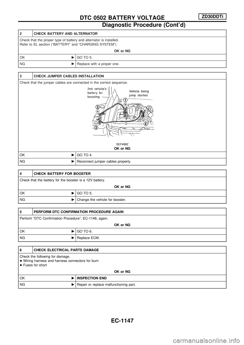
3 CHECK JUMPER CABLES INSTALLATION
Check that the jumper cables are connected in the correct sequence.
SEF488Z
OK or NG
OKcGO TO 4.
NGcReconnect jumper cables properly.
4 CHECK BATTERY FOR BOOSTER
Check that the battery for the booster is a 12V battery.
OK or NG
OKcGO TO 5.
NGcChange the vehicle for booster.
5 PERFORM DTC CONFIRMATION PROCEDURE AGAIN
Perform ªDTC Confirmation Procedureº, EC-1146, again.
OK or NG
OKcGO TO 6.
NGcReplace ECM.
6 CHECK ELECTRICAL PARTS DAMAGE
Check the following for damage.
+Wiring harness and harness connectors for burn
+Fuses for short
OK or NG
OKcINSPECTION END
NGcRepair or replace malfunctioning part.
DTC 0502 BATTERY VOLTAGEZD30DDTi
Diagnostic Procedure (Cont'd)
EC-1147
Page 424 of 1033
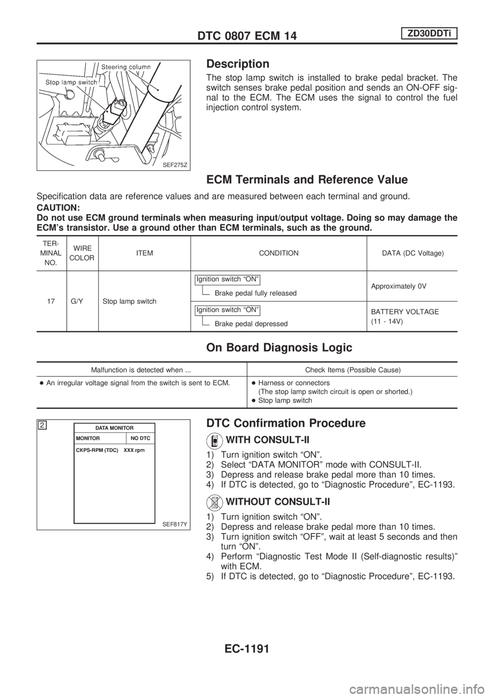
Description
The stop lamp switch is installed to brake pedal bracket. The
switch senses brake pedal position and sends an ON-OFF sig-
nal to the ECM. The ECM uses the signal to control the fuel
injection control system.
ECM Terminals and Reference Value
Specification data are reference values and are measured between each terminal and ground.
CAUTION:
Do not use ECM ground terminals when measuring input/output voltage. Doing so may damage the
ECM's transistor. Use a ground other than ECM terminals, such as the ground.
TER-
MINAL
NO.WIRE
COLORITEM CONDITION DATA (DC Voltage)
17 G/Y Stop lamp switchIgnition switch ªONº
Brake pedal fully releasedApproximately 0V
Ignition switch ªONº
Brake pedal depressedBATTERY VOLTAGE
(11 - 14V)
On Board Diagnosis Logic
Malfunction is detected when ... Check Items (Possible Cause)
+An irregular voltage signal from the switch is sent to ECM.+Harness or connectors
(The stop lamp switch circuit is open or shorted.)
+Stop lamp switch
DTC Confirmation Procedure
WITH CONSULT-II
1) Turn ignition switch ªONº.
2) Select ªDATA MONITORº mode with CONSULT-II.
3) Depress and release brake pedal more than 10 times.
4) If DTC is detected, go to ªDiagnostic Procedureº, EC-1193.
WITHOUT CONSULT-II
1) Turn ignition switch ªONº.
2) Depress and release brake pedal more than 10 times.
3) Turn ignition switch ªOFFº, wait at least 5 seconds and then
turn ªONº.
4) Perform ªDiagnostic Test Mode II (Self-diagnostic results)º
with ECM.
5) If DTC is detected, go to ªDiagnostic Procedureº, EC-1193.
SEF275Z
SEF817Y
DTC 0807 ECM 14ZD30DDTi
EC-1191
Page 429 of 1033
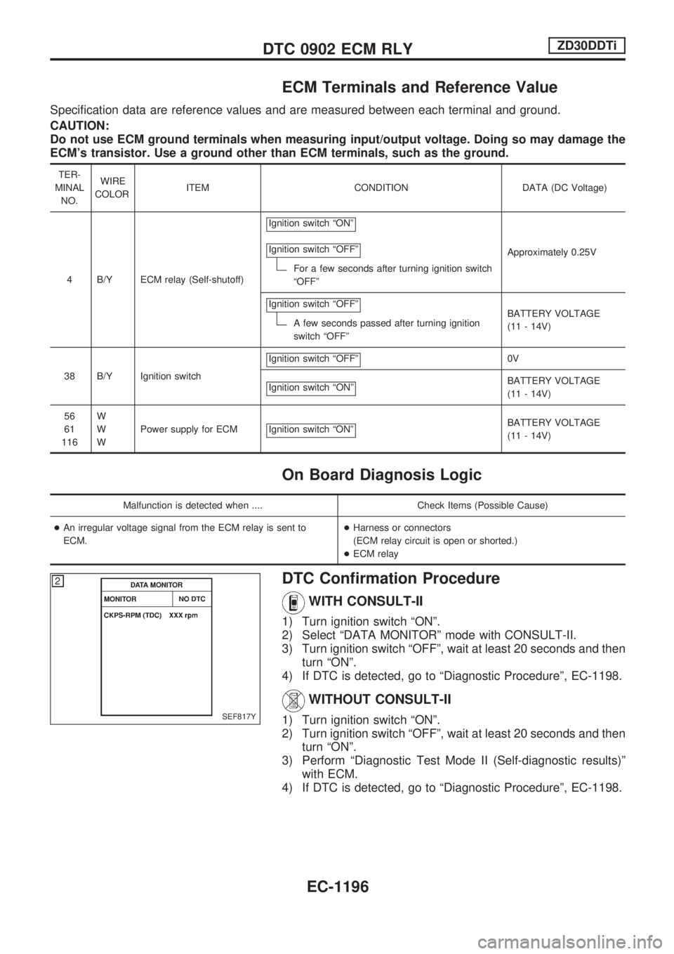
ECM Terminals and Reference Value
Specification data are reference values and are measured between each terminal and ground.
CAUTION:
Do not use ECM ground terminals when measuring input/output voltage. Doing so may damage the
ECM's transistor. Use a ground other than ECM terminals, such as the ground.
TER-
MINAL
NO.WIRE
COLORITEM CONDITION DATA (DC Voltage)
4 B/Y ECM relay (Self-shutoff)Ignition switch ªONº
Ignition switch ªOFFº
For a few seconds after turning ignition switch
ªOFFºApproximately 0.25V
Ignition switch ªOFFº
A few seconds passed after turning ignition
switch ªOFFºBATTERY VOLTAGE
(11 - 14V)
38 B/Y Ignition switchIgnition switch ªOFFº
0V
Ignition switch ªONº
BATTERY VOLTAGE
(11 - 14V)
56
61
116W
W
WPower supply for ECM Ignition switch ªONº
BATTERY VOLTAGE
(11 - 14V)
On Board Diagnosis Logic
Malfunction is detected when .... Check Items (Possible Cause)
+An irregular voltage signal from the ECM relay is sent to
ECM.+Harness or connectors
(ECM relay circuit is open or shorted.)
+ECM relay
DTC Confirmation Procedure
WITH CONSULT-II
1) Turn ignition switch ªONº.
2) Select ªDATA MONITORº mode with CONSULT-II.
3) Turn ignition switch ªOFFº, wait at least 20 seconds and then
turn ªONº.
4) If DTC is detected, go to ªDiagnostic Procedureº, EC-1198.
WITHOUT CONSULT-II
1) Turn ignition switch ªONº.
2) Turn ignition switch ªOFFº, wait at least 20 seconds and then
turn ªONº.
3) Perform ªDiagnostic Test Mode II (Self-diagnostic results)º
with ECM.
4) If DTC is detected, go to ªDiagnostic Procedureº, EC-1198.SEF817Y
DTC 0902 ECM RLYZD30DDTi
EC-1196