Page 431 of 1033
Diagnostic Procedure
1 CHECK ECM POWER SUPPLY CIRCUIT
1. Turn ignition switch ªOFFº.
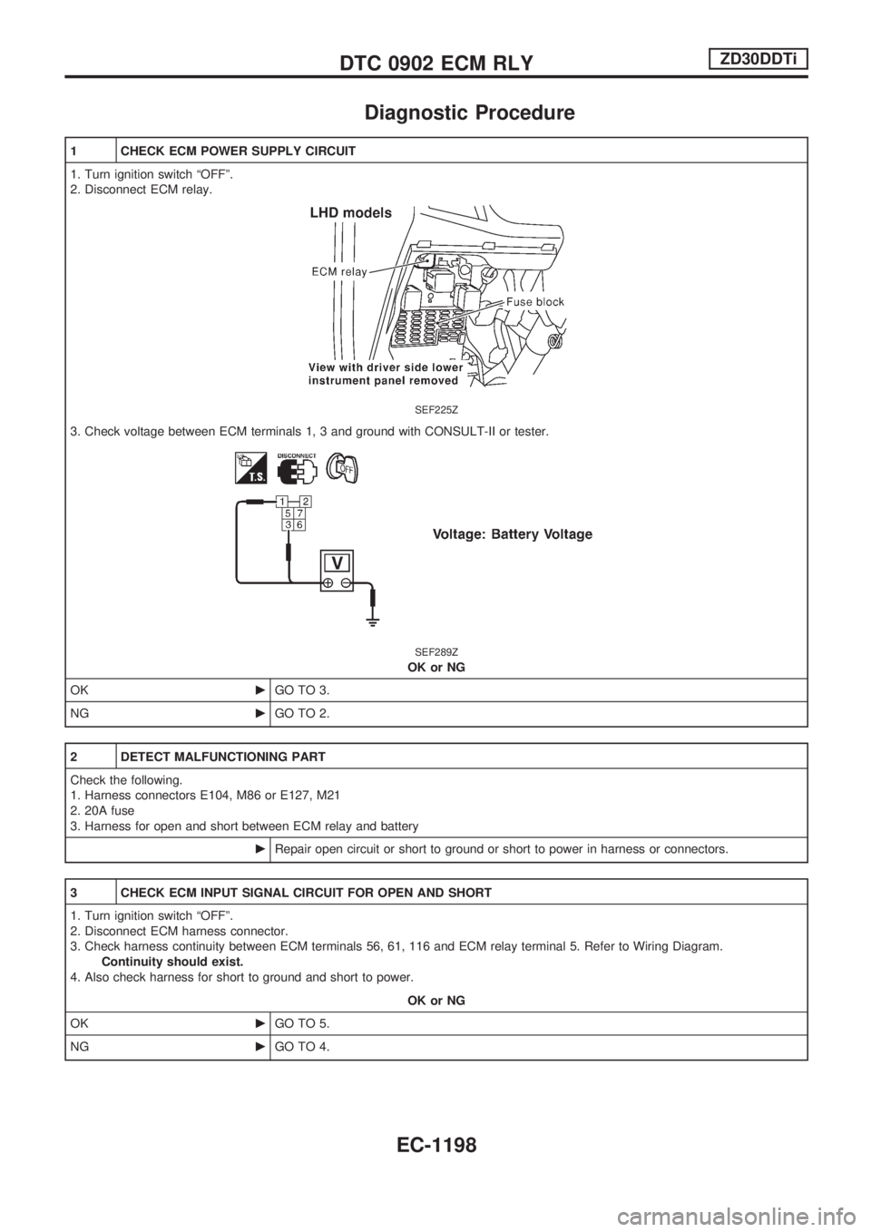
2. Disconnect ECM relay.
SEF225Z
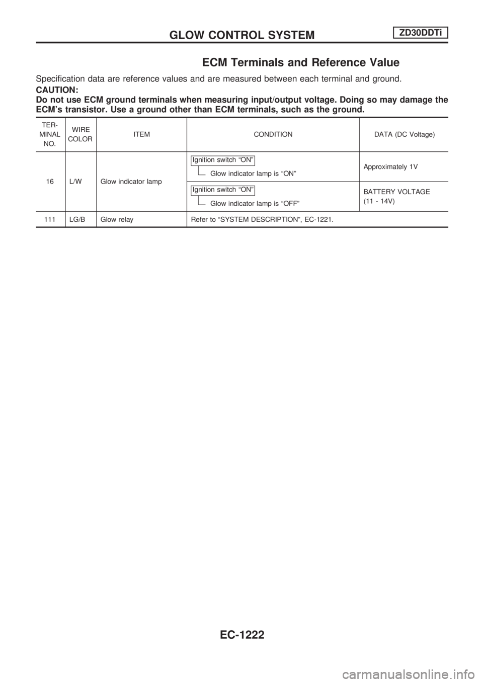
3. Check voltage between ECM terminals 1, 3 and ground with CONSULT-II or tester.
SEF289Z
OK or NG
OKcGO TO 3.
NGcGO TO 2.
2 DETECT MALFUNCTIONING PART
Check the following.
1. Harness connectors E104, M86 or E127, M21
2. 20A fuse
3. Harness for open and short between ECM relay and battery
cRepair open circuit or short to ground or short to power in harness or connectors.
3 CHECK ECM INPUT SIGNAL CIRCUIT FOR OPEN AND SHORT
1. Turn ignition switch ªOFFº.
2. Disconnect ECM harness connector.
3. Check harness continuity between ECM terminals 56, 61, 116 and ECM relay terminal 5. Refer to Wiring Diagram.
Continuity should exist.
4. Also check harness for short to ground and short to power.
OK or NG
OKcGO TO 5.
NGcGO TO 4.
DTC 0902 ECM RLYZD30DDTi
EC-1198
Page 440 of 1033
Description
SYSTEM DESCRIPTION
Sensor Input Signal to ECM ECM Function Actuator
Electronic controlled fuel injection pump Fuel injection signal
EGR volume control EGR volume control valve Crankshaft position sensor (TDC) Engine speed
Vehicle speed sensor Vehicle speed
Engine coolant temperature sensor Engine coolant temperature
Ignition switch Start signal
Throttle position sensor Throttle position
Battery Battery voltage
Mass air flow sensor Amount of intake air
Air conditioner switch Air conditioner operation
Electrical load Electrical load signal
PNP switch Park/Neutral position signal
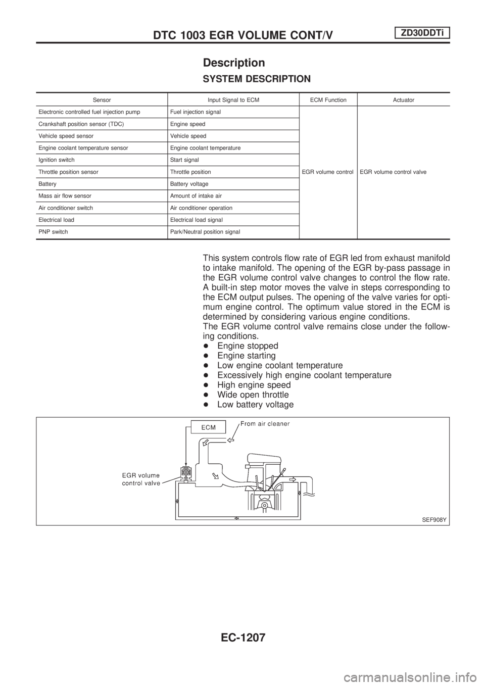
This system controls flow rate of EGR led from exhaust manifold
to intake manifold. The opening of the EGR by-pass passage in
the EGR volume control valve changes to control the flow rate.
A built-in step motor moves the valve in steps corresponding to
the ECM output pulses. The opening of the valve varies for opti-
mum engine control. The optimum value stored in the ECM is
determined by considering various engine conditions.
The EGR volume control valve remains close under the follow-
ing conditions.
+Engine stopped
+Engine starting
+Low engine coolant temperature
+Excessively high engine coolant temperature
+High engine speed
+Wide open throttle
+Low battery voltage
SEF908Y
DTC 1003 EGR VOLUME CONT/VZD30DDTi
EC-1207
Page 444 of 1033
2 CHECK EGR VOLUME CONTROL VALVE POWER SUPPLY CIRCUIT-II
1. Turn ignition switch ªOFFº.
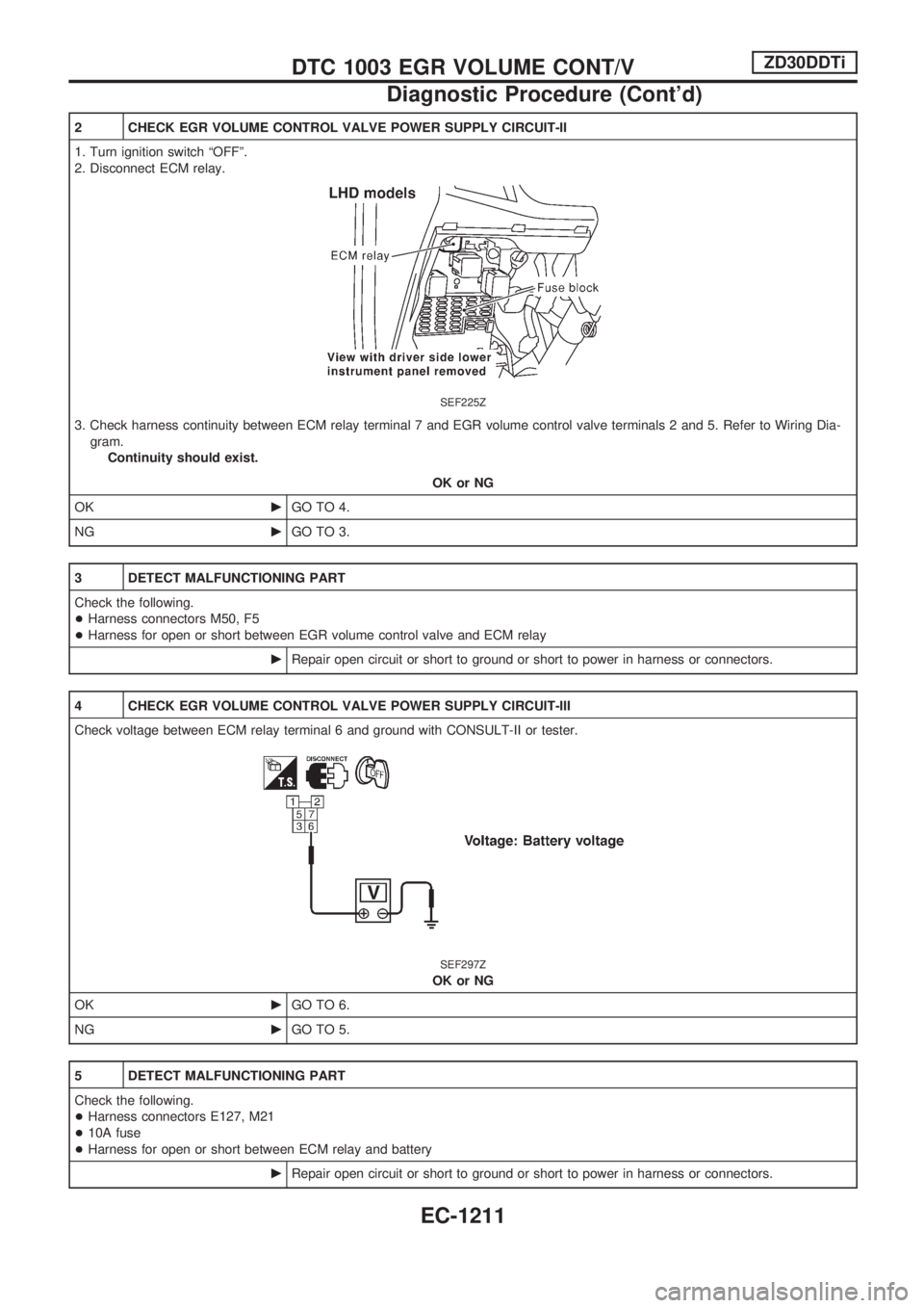
2. Disconnect ECM relay.
SEF225Z
3. Check harness continuity between ECM relay terminal 7 and EGR volume control valve terminals 2 and 5. Refer to Wiring Dia-
gram.
Continuity should exist.
OK or NG
OKcGO TO 4.
NGcGO TO 3.
3 DETECT MALFUNCTIONING PART
Check the following.
+Harness connectors M50, F5
+Harness for open or short between EGR volume control valve and ECM relay
cRepair open circuit or short to ground or short to power in harness or connectors.
4 CHECK EGR VOLUME CONTROL VALVE POWER SUPPLY CIRCUIT-III
Check voltage between ECM relay terminal 6 and ground with CONSULT-II or tester.
SEF297Z
OK or NG
OKcGO TO 6.
NGcGO TO 5.
5 DETECT MALFUNCTIONING PART
Check the following.
+Harness connectors E127, M21
+10A fuse
+Harness for open or short between ECM relay and battery
cRepair open circuit or short to ground or short to power in harness or connectors.
DTC 1003 EGR VOLUME CONT/VZD30DDTi
Diagnostic Procedure (Cont'd)
EC-1211
Page 455 of 1033
ECM Terminals and Reference Value
Specification data are reference values and are measured between each terminal and ground.
CAUTION:
Do not use ECM ground terminals when measuring input/output voltage. Doing so may damage the
ECM's transistor. Use a ground other than ECM terminals, such as the ground.
TER-
MINAL
NO.WIRE
COLORITEM CONDITION DATA (DC Voltage)
16 L/W Glow indicator lampIgnition switch ªONº
Glow indicator lamp is ªONºApproximately 1V
Ignition switch ªONº
Glow indicator lamp is ªOFFºBATTERY VOLTAGE
(11 - 14V)
111 LG/B Glow relay Refer to ªSYSTEM DESCRIPTIONº, EC-1221.
GLOW CONTROL SYSTEMZD30DDTi
EC-1222
Page 460 of 1033
11 CHECK GLOW RELAY POWER SUPPLY CIRCUIT
1. Turn ignition switch ªOFFº.
2. Disconnect glow relay.
SEF235Z
3. Check voltage between glow relay terminals 1, 3 and ground with CONSULT-II or tester.
SEF451Z
OK or NG
OKcGO TO 13.
NGcGO TO 12.
12 DETECT MALFUNCTIONING PART
Check the following.
+100A fusible link
+Harness for open or short between glow relay and battery
cRepair harness or connectors.
13 CHECK GLOW RELAY OUTPUT SIGNAL CIRCUIT FOR OPEN AND SHORT
1. Disconnect ECM harness connector.
2. Check harness continuity between ECM terminal 111 and glow relay terminal 2. Refer to Wiring Diagram.
Continuity should exist.
3. Also check harness for short to ground and short to power.
OK or NG
OKcGO TO 15.
NGcGO TO 14.
GLOW CONTROL SYSTEMZD30DDTi
Diagnostic Procedure (Cont'd)
EC-1227
Page 466 of 1033
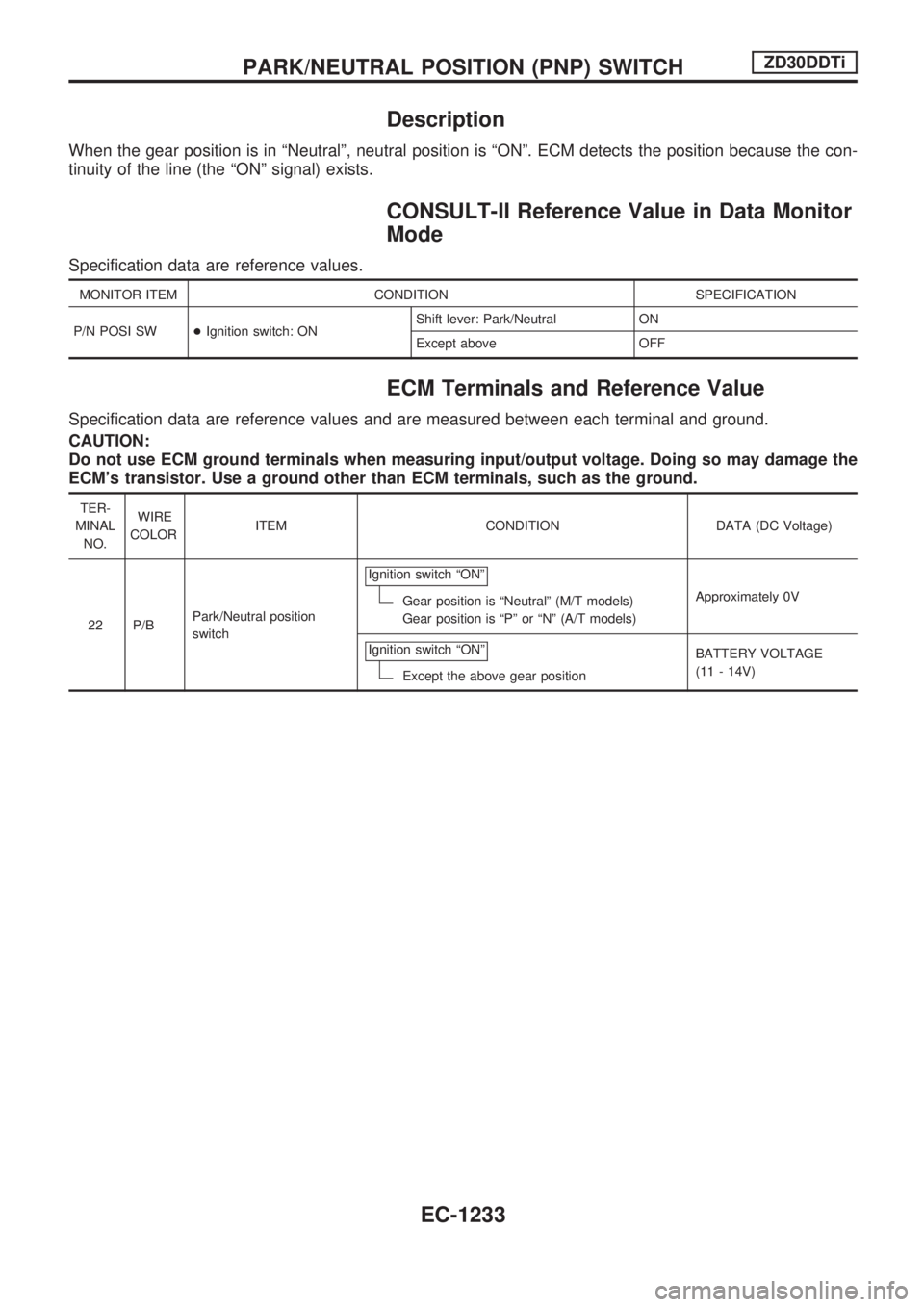
Description
When the gear position is in ªNeutralº, neutral position is ªONº. ECM detects the position because the con-
tinuity of the line (the ªONº signal) exists.
CONSULT-II Reference Value in Data Monitor
Mode
Specification data are reference values.
MONITOR ITEM CONDITION SPECIFICATION
P/N POSI SW+Ignition switch: ONShift lever: Park/Neutral ON
Except above OFF
ECM Terminals and Reference Value
Specification data are reference values and are measured between each terminal and ground.
CAUTION:
Do not use ECM ground terminals when measuring input/output voltage. Doing so may damage the
ECM's transistor. Use a ground other than ECM terminals, such as the ground.
TER-
MINAL
NO.WIRE
COLORITEM CONDITION DATA (DC Voltage)
22 P/BPark/Neutral position
switchIgnition switch ªONº
Gear position is ªNeutralº (M/T models)
Gear position is ªPº or ªNº (A/T models)Approximately 0V
Ignition switch ªONº
Except the above gear positionBATTERY VOLTAGE
(11 - 14V)
PARK/NEUTRAL POSITION (PNP) SWITCHZD30DDTi
EC-1233
Page 474 of 1033
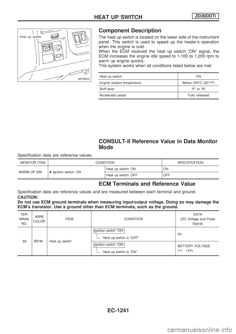
Component Description
The heat up switch is located on the lower side of the instrument
panel. This switch is used to speed up the heater's operation
when the engine is cold.
When the ECM received the heat up switch ªONº signal, the
ECM increases the engine idle speed to 1,100 to 1,200 rpm to
warm up engine quickly.
This system works when all conditions listed below are met.
Heat up switch ON
Engine coolant temperature Below 105ÉC (221ÉF)
Shift lever ªPº or ªNº
Accelerator pedal Fully released
CONSULT-II Reference Value in Data Monitor
Mode
Specification data are reference values.
MONITOR ITEM CONDITION SPECIFICATION
WARM UP SW+Ignition switch: ONHeat up switch: ON ON
Heat up switch: OFF OFF
ECM Terminals and Reference Value
Specification data are reference values and are measured between each terminal and ground.
CAUTION:
Do not use ECM ground terminals when measuring input/output voltage. Doing so may damage the
ECM's transistor. Use a ground other than ECM terminals, such as the ground.
TER-
MINAL
NO.WIRE
COLORITEM CONDITIONDATA
(DC Voltage and Pulse
Signal)
59 BR/W Heat up switchIgnition switch ªONº
Heat up switch is ªOFFº.0V
Ignition switch ªONº
Heat up switch is ªONº.BATTERY VOLTAGE
(11 - 14V)
SEF803V
HEAT UP SWITCHZD30DDTi
EC-1241
Page 480 of 1033
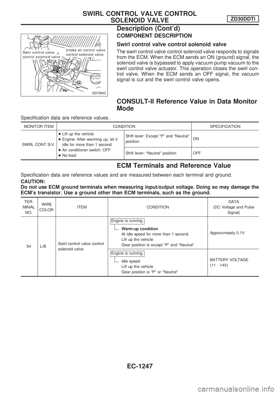
COMPONENT DESCRIPTION
Swirl control valve control solenoid valve
The swirl control valve control solenoid valve responds to signals
from the ECM. When the ECM sends an ON (ground) signal, the
solenoid valve is bypassed to apply vacuum pump vacuum to the
swirl control valve actuator. This operation closes the swirl con-
trol valve. When the ECM sends an OFF signal, the vacuum
signal is cut and the swirl control valve opens.
CONSULT-II Reference Value in Data Monitor
Mode
Specification data are reference values.
MONITOR ITEM CONDITION SPECIFICATION
SWRL CONT S/V+Lift up the vehicle
+Engine: After warming up, let it
idle for more than 1 second.
+Air conditioner switch: OFF
+No-loadShift lever: Except ªPº and ªNeutralº
positionON
Shift lever: ªNeutralº position OFF
ECM Terminals and Reference Value
Specification data are reference values and are measured between each terminal and ground.
CAUTION:
Do not use ECM ground terminals when measuring input/output voltage. Doing so may damage the
ECM's transistor. Use a ground other than ECM terminals, such as the ground.
TER-
MINAL
NO.WIRE
COLORITEM CONDITIONDATA
(DC Voltage and Pulse
Signal)
54 L/BSwirl control valve control
solenoid valveEngine is running.
Warm-up condition
At idle speed for more than 1 second.
Lift up the vehicle
Gear position is except ªPº and ªNeutralºApproximately 0.1V
Engine is running.
Idle speed
Lift up the vehicle
Gear position is ªPº or ªNeutralºBATTERY VOLTAGE
(11 - 14V)
SEF284Z
SWIRL CONTROL VALVE CONTROL
SOLENOID VALVEZD30DDTi
Description (Cont'd)
EC-1247