Page 1 of 1033
Edition: February 2000
Release: February 2000 (01)
Publication No.: SM0E-Y61AE0E
Reference No.: 7711346024GENERAL INFORMATIONGI
MAINTENANCEMA
ENGINE MECHANICALEM
ENGINE LUBRICATION &
COOLING SYSTEMSLC
ENGINE CONTROL SYSTEMEC
ACCELERATOR CONTROL,
FUEL & EXHAUST SYSTEMFE
CLUTCHCL
MANUAL TRANSMISSIONMT
AUTOMATIC TRANSMISSIONAT
TRANSFERTF
PROPELLER SHAFT &
DIFFERENTIAL CARRIERPD
FRONT AXLE & FRONT SUSPENSIONFA
REAR AXLE & REAR SUSPENSIONRA
BRAKE SYSTEMBR
STEERING SYSTEMST
RESTRAINT SYSTEMRS
BODY & TRIMBT
HEATER & AIR CONDITIONERHA
ELECTRICAL SYSTEMEL
ALPHABETICAL INDEXIDX
PATROL GR
MODEL Y61 SERIES
NISSAN EUROPE S.A.S.
2000 NISSAN EUROPE S.A.S.
Produced in The Netherlands
Not to be reproduced in whole or in part
without the prior written permission of
Nissan Europe S.A.S., Paris, France.
QUICK REFERENCE INDEX
Page 7 of 1033
+Extreme care should be taken to avoid damage to O-rings, seals and gaskets when assembling.
+After overhaul, refill the transmission with new ATF.
+When the A/T drain plug is removed, only some of the fluid is drained. Old A/T fluid will remain in torque
converter and ATF cooling system.
Always follow the procedures under ªChanging A/T Fluidº in the MA section when changing A/T fluid.
PREPARATION AND PRECAUTIONS
Precautions (Cont'd)
AT-1005
Page 136 of 1033
6. Place transmission into Tool with the control valve facing up.
7. Check foreign materials in oil pan to help determine cause of
malfunction. If the fluid is very dark, smells burned, or con-
tains foreign particles, the frictional material (clutches, band)
may need replacement. A tacky film that will not wipe clean
indicates varnish build up. Varnish can cause valves, servo,
and clutches to stick and may inhibit pump pressure.
+If frictional material is detected, replace radiator after
repair of A/T. Refer to LC section (ªRadiatorº, ªENGINE
COOLING SYSTEMº).
8. Remove torque converter clutch solenoid valve and A/T fluid
temperature sensor connectors.
+Be careful not to damage connector.
9. Remove oil strainer.
a. Remove oil strainer from control valve assembly.
Then remove O-ring from oil strainer.
b. Check oil strainer screen for damage.
SAT522GA
SAT171B
SAT024BA
SAT008B
SAT025B
DISASSEMBLY
AT-1134
Page 251 of 1033

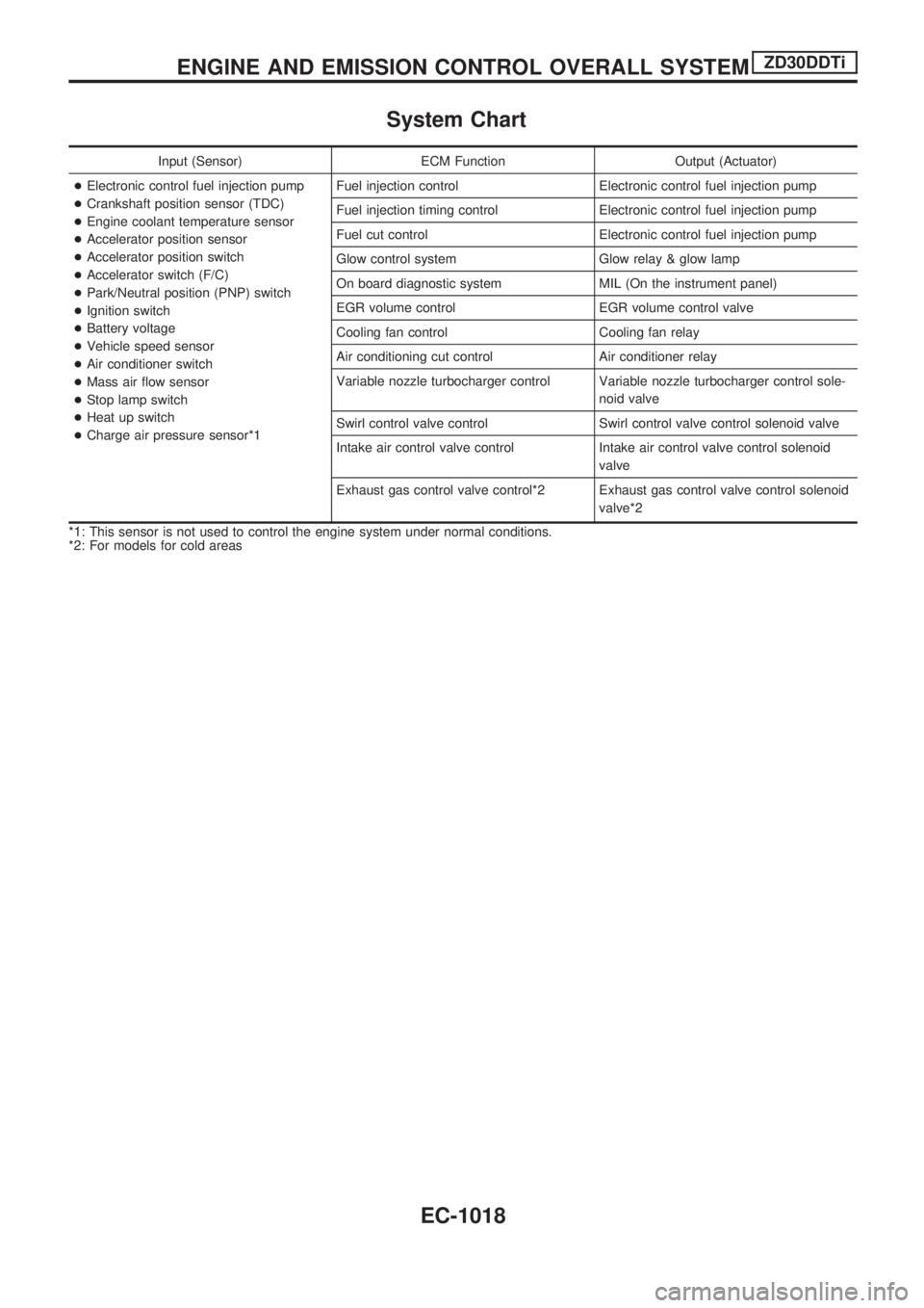
System Chart
Input (Sensor) ECM Function Output (Actuator)
+Electronic control fuel injection pump
+Crankshaft position sensor (TDC)
+Engine coolant temperature sensor
+Accelerator position sensor
+Accelerator position switch
+Accelerator switch (F/C)
+Park/Neutral position (PNP) switch
+Ignition switch
+Battery voltage
+Vehicle speed sensor
+Air conditioner switch
+Mass air flow sensor
+Stop lamp switch
+Heat up switch
+Charge air pressure sensor*1Fuel injection control Electronic control fuel injection pump
Fuel injection timing control Electronic control fuel injection pump
Fuel cut control Electronic control fuel injection pump
Glow control system Glow relay & glow lamp
On board diagnostic system MIL (On the instrument panel)
EGR volume control EGR volume control valve
Cooling fan control Cooling fan relay
Air conditioning cut control Air conditioner relay
Variable nozzle turbocharger control Variable nozzle turbocharger control sole-
noid valve
Swirl control valve control Swirl control valve control solenoid valve
Intake air control valve control Intake air control valve control solenoid
valve
Exhaust gas control valve control*2 Exhaust gas control valve control solenoid
valve*2
*1: This sensor is not used to control the engine system under normal conditions.
*2: For models for cold areas
ENGINE AND EMISSION CONTROL OVERALL SYSTEMZD30DDTi
EC-1018
Page 260 of 1033

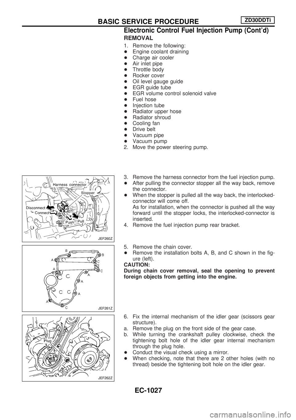
REMOVAL
1. Remove the following:
+Engine coolant draining
+Charge air cooler
+Air inlet pipe
+Throttle body
+Rocker cover
+Oil level gauge guide
+EGR guide tube
+EGR volume control solenoid valve
+Fuel hose
+Injection tube
+Radiator upper hose
+Radiator shroud
+Cooling fan
+Drive belt
+Vacuum pipe
+Vacuum pump
2. Move the power steering pump.
3. Remove the harness connector from the fuel injection pump.
+After pulling the connector stopper all the way back, remove
the connector.
+When the stopper is pulled all the way back, the interlocked-
connector will come off.
As for installation, when the connector is pushed all the way
forward until the stopper locks, the interlocked-connector is
inserted.
4. Remove the fuel injection pump rear bracket.
5. Remove the chain cover.
+Remove the installation bolts A, B, and C shown in the fig-
ure (left).
CAUTION:
During chain cover removal, seal the opening to prevent
foreign objects from getting into the engine.
6. Fix the internal mechanism of the idler gear (scissors gear
structure).
a. Remove the plug on the front side of the gear case.
b. While turning the crankshaft pulley clockwise, check the
tightening bolt hole of the idler gear internal mechanism
through the plug hole.
+Conduct the visual check using a mirror.
+When checking, note that there are 2 other holes (with no
thread) beside the tightening bolt hole on the idler gear.
JEF260Z
JEF261Z
JEF262Z
BASIC SERVICE PROCEDUREZD30DDTi
Electronic Control Fuel Injection Pump (Cont'd)
EC-1027
Page 272 of 1033

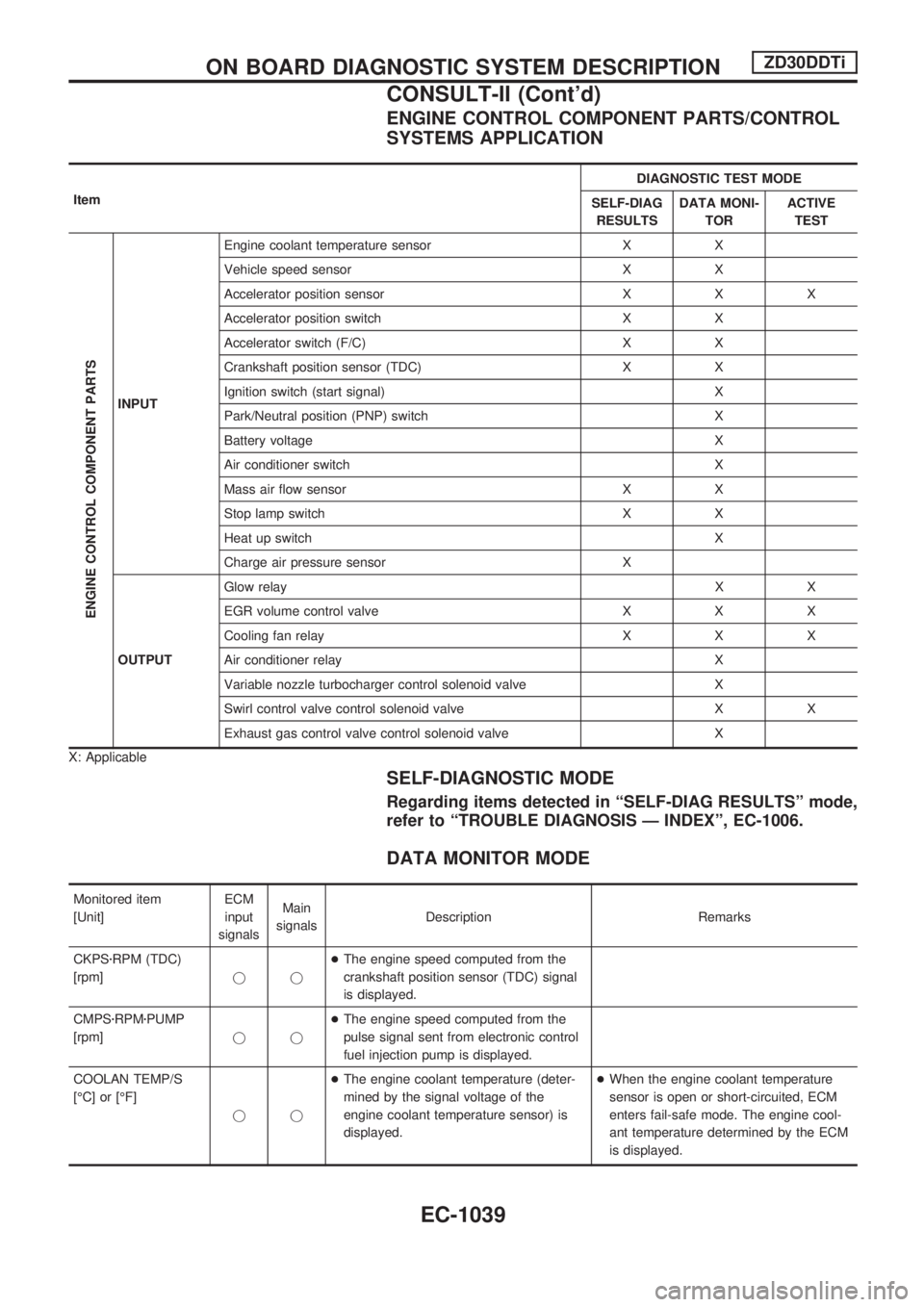
ENGINE CONTROL COMPONENT PARTS/CONTROL
SYSTEMS APPLICATION
ItemDIAGNOSTIC TEST MODE
SELF-DIAG
RESULTSDATA MONI-
TORACTIVE
TEST
ENGINE CONTROL COMPONENT PARTS
INPUTEngine coolant temperature sensor X X
Vehicle speed sensor X X
Accelerator position sensor X X X
Accelerator position switch X X
Accelerator switch (F/C) X X
Crankshaft position sensor (TDC) X X
Ignition switch (start signal) X
Park/Neutral position (PNP) switch X
Battery voltage X
Air conditioner switch X
Mass air flow sensor X X
Stop lamp switch X X
Heat up switch X
Charge air pressure sensor X
OUTPUTGlow relayXX
EGR volume control valve X X X
Cooling fan relay X X X
Air conditioner relay X
Variable nozzle turbocharger control solenoid valve X
Swirl control valve control solenoid valve X X
Exhaust gas control valve control solenoid valve X
X: Applicable
SELF-DIAGNOSTIC MODE
Regarding items detected in ªSELF-DIAG RESULTSº mode,
refer to ªTROUBLE DIAGNOSIS Ð INDEXº, EC-1006.
DATA MONITOR MODE
Monitored item
[Unit]ECM
input
signalsMain
signalsDescription Remarks
CKPSzRPM (TDC)
[rpm]jj+The engine speed computed from the
crankshaft position sensor (TDC) signal
is displayed.
CMPSzRPMzPUMP
[rpm]jj+The engine speed computed from the
pulse signal sent from electronic control
fuel injection pump is displayed.
COOLAN TEMP/S
[ÉC] or [ÉF]
jj+The engine coolant temperature (deter-
mined by the signal voltage of the
engine coolant temperature sensor) is
displayed.+When the engine coolant temperature
sensor is open or short-circuited, ECM
enters fail-safe mode. The engine cool-
ant temperature determined by the ECM
is displayed.
ON BOARD DIAGNOSTIC SYSTEM DESCRIPTIONZD30DDTi
CONSULT-II (Cont'd)
EC-1039
Page 274 of 1033
![NISSAN PATROL 2000 Electronic Repair Manual Monitored item
[Unit]ECM
input
signalsMain
signalsDescription Remarks
COOLING FAN
[ON/OFF]
j+Indicates the control condition of the
cooling fans (determined by ECM
according to the input signal).
+ON NISSAN PATROL 2000 Electronic Repair Manual Monitored item
[Unit]ECM
input
signalsMain
signalsDescription Remarks
COOLING FAN
[ON/OFF]
j+Indicates the control condition of the
cooling fans (determined by ECM
according to the input signal).
+ON](/manual-img/5/57367/w960_57367-273.png)
Monitored item
[Unit]ECM
input
signalsMain
signalsDescription Remarks
COOLING FAN
[ON/OFF]
j+Indicates the control condition of the
cooling fans (determined by ECM
according to the input signal).
+ON ... Operates.
OFF ... Stopped.
EGR VOL CON/V
[step]
j+Indicates the EGR volume control value
computed by the ECM according to the
input signals.
+The opening becomes larger as the
value increases.
VNT S/V 1 [%]+Indicates the variable nozzle turbo-
charger control solenoid valve control
value computed by the ECM according
to the input signals.
BARO SEN [kPa]
j+The barometric pressure (determined by
the signal voltage from the barometric
pressure sensor built into the ECM) is
displayed.
SWRL CON S/V 1
[ON/OFF]
j+The control condition of the swirl control
valve control solenoid valve (determined
by ECM according to the input signals)
is indicated.
+ON ... Swirl control valve is closed.
+OFF ... Swirl control valve is opened.
EXH/GAS REG V
[ON/OFF]+The control condition of the exhaust gas
control valve control solenoid valve
(computed by ECM according to the
input signals) is indicated.
+ON ... Exhaust gas control valve is
closed.
+OFF ... Exhaust gas control valve is
opened.+This item is applicable for cold area
models.
On other models, ªOFFº is always dis-
played.
NOTE:
Any monitored item that does not match the vehicle being diagnosed is deleted from the display automatically.
ON BOARD DIAGNOSTIC SYSTEM DESCRIPTIONZD30DDTi
CONSULT-II (Cont'd)
EC-1041
Page 275 of 1033

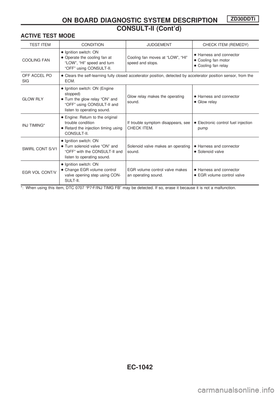
ACTIVE TEST MODE
TEST ITEM CONDITION JUDGEMENT CHECK ITEM (REMEDY)
COOLING FAN+Ignition switch: ON
+Operate the cooling fan at
ªLOWº, ªHIº speed and turn
ªOFFº using CONSULT-II.Cooling fan moves at ªLOWº, ªHIº
speed and stops.+Harness and connector
+Cooling fan motor
+Cooling fan relay
OFF ACCEL PO
SIG+Clears the self-learning fully closed accelerator position, detected by accelerator position sensor, from the
ECM.
GLOW RLY+Ignition switch: ON (Engine
stopped)
+Turn the glow relay ªONº and
ªOFFº using CONSULT-II and
listen to operating sound.Glow relay makes the operating
sound.+Harness and connector
+Glow relay
INJ TIMING*+Engine: Return to the original
trouble condition
+Retard the injection timing using
CONSULT-II.If trouble symptom disappears, see
CHECK ITEM.+Electronic control fuel injection
pump
SWIRL CONT S/V1+Ignition switch: ON
+Turn solenoid valve ªONº and
ªOFFº with the CONSULT-II and
listen to operating sound.Solenoid valve makes an operating
sound.+Harness and connector
+Solenoid valve
EGR VOL CONT/V+Ignition switch: ON
+Change EGR volume control
valve opening step using CON-
SULT-II.EGR volume control valve makes
an operating sound.+Harness and connector
+EGR volume control valve
*: When using this item, DTC 0707 ªP7zF/INJ TIMG FBº may be detected. If so, erase it because it is not a malfunction.
ON BOARD DIAGNOSTIC SYSTEM DESCRIPTIONZD30DDTi
CONSULT-II (Cont'd)
EC-1042