Page 298 of 1033
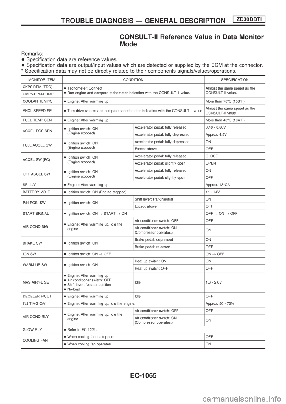
CONSULT-II Reference Value in Data Monitor
Mode
Remarks:
+Specification data are reference values.
+Specification data are output/input values which are detected or supplied by the ECM at the connector.
* Specification data may not be directly related to their components signals/values/operations.
MONITOR ITEM CONDITION SPECIFICATION
CKPSzRPM (TDC)
+Tachometer: Connect
+Run engine and compare tachometer indication with the CONSULT-II value.Almost the same speed as the
CONSULT-II value.
CMPSzRPM-PUMP
COOLAN TEMP/S+Engine: After warming up More than 70ÉC (158ÉF)
VHCL SPEED SE+Turn drive wheels and compare speedometer indication with the CONSULT-II valueAlmost the same speed as the
CONSULT-II value
FUEL TEMP SEN+Engine: After warming up More than 40ÉC (104ÉF)
ACCEL POS SEN+Ignition switch: ON
(Engine stopped)Accelerator pedal: fully released 0.40 - 0.60V
Accelerator pedal: fully depressed Approx. 4.5V
FULL ACCEL SW+Ignition switch: ON
(Engine stopped)Accelerator pedal: fully depressed ON
Except above OFF
ACCEL SW (FC)+Ignition switch: ON
(Engine stopped)Accelerator pedal: fully released CLOSE
Accelerator pedal: slightly open OPEN
OFF ACCEL SW+Ignition switch: ON
(Engine stopped)Accelerator pedal: fully released ON
Accelerator pedal: slightly open OFF
SPILL/V+Engine: After warming up Approx. 13ÉCA
BATTERY VOLT+Ignition switch: ON (Engine stopped) 11 - 14V
P/N POSI SW+Ignition switch: ONShift lever: Park/Neutral ON
Except above OFF
START SIGNAL+Ignition switch: ON®START®ON OFF®ON®OFF
AIR COND SIG+Engine: After warming up, idle the
engineAir conditioner switch: OFF OFF
Air conditioner switch: ON
(Compressor operates.)ON
BRAKE SW+Ignition switch: ONBrake pedal: depressed ON
Brake pedal: released OFF
IGN SW+Ignition switch: ON®OFF ON®OFF
WARM UP SW+Ignition switch: ONHeat up switch: ON ON
Heat up switch: OFF OFF
MAS AIR/FL SE+Engine: After warming up
+Air conditioner switch: OFF
+Shift lever: Neutral position
+No-loadIdle 1.6 - 2.0V
DECELER F/CUT+Engine: After warming up Idle OFF
INJ TIMG C/V+Engine: After warming up, idle the engine. Approx. 50 - 70%
AIR COND RLY+Engine: After warming up, idle the
engineAir conditioner switch: OFF OFF
Air conditioner switch: ON
(Compressor operates.)ON
GLOW RLY+Refer to EC-1221.
COOLING FAN+When cooling fan is stopped. OFF
+When cooling fan operates. ON
TROUBLE DIAGNOSIS Ð GENERAL DESCRIPTIONZD30DDTi
EC-1065
Page 303 of 1033
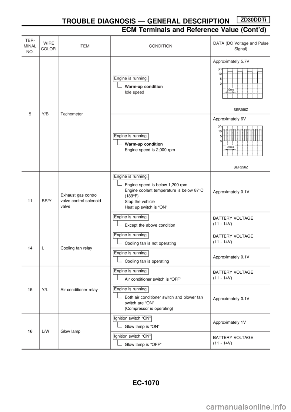
TER-
MINAL
NO.WIRE
COLORITEM CONDITIONDATA (DC Voltage and Pulse
Signal)
5 Y/B TachometerEngine is running.
Warm-up condition
Idle speedApproximately 5.7V
SEF255Z
Engine is running.
Warm-up condition
Engine speed is 2,000 rpmApproximately 6V
SEF256Z
11 BR/YExhaust gas control
valve control solenoid
valveEngine is running.
Engine speed is below 1,200 rpm
Engine coolant temperature is below 87ÉC
(189ÉF)
Stop the vehicle
Heat up switch is ªONºApproximately 0.1V
Engine is running.
Except the above conditionBATTERY VOLTAGE
(11 - 14V)
14 L Cooling fan relayEngine is running.
Cooling fan is not operatingBATTERY VOLTAGE
(11 - 14V)
Engine is running.
Cooling fan is operatingApproximately 0.1V
15 Y/L Air conditioner relayEngine is running.
Air conditioner switch is ªOFFºBATTERY VOLTAGE
(11 - 14V)
Engine is running.
Both air conditioner switch and blower fan
switch are ªONº
(Compressor is operating)Approximately 0.1V
16 L/W Glow lampIgnition switch ªONº
Glow lamp is ªONºApproximately 1V
Ignition switch ªONº
Glow lamp is ªOFFºBATTERY VOLTAGE
(11 - 14V)
TROUBLE DIAGNOSIS Ð GENERAL DESCRIPTIONZD30DDTi
ECM Terminals and Reference Value (Cont'd)
EC-1070
Page 338 of 1033
Description
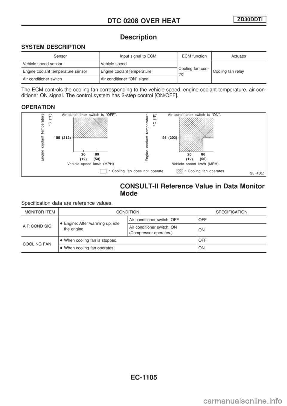
SYSTEM DESCRIPTION
Sensor Input signal to ECM ECM function Actuator
Vehicle speed sensor Vehicle speed
Cooling fan con-
trolCooling fan relay Engine coolant temperature sensor Engine coolant temperature
Air conditioner switch Air conditioner ªONº signal
The ECM controls the cooling fan corresponding to the vehicle speed, engine coolant temperature, air con-
ditioner ON signal. The control system has 2-step control [ON/OFF].
OPERATION
CONSULT-II Reference Value in Data Monitor
Mode
Specification data are reference values.
MONITOR ITEM CONDITION SPECIFICATION
AIR COND SIG+Engine: After warming up, idle
the engineAir conditioner switch: OFF OFF
Air conditioner switch: ON
(Compressor operates.)ON
COOLING FAN+When cooling fan is stopped. OFF
+When cooling fan operates. ON
SEF450Z
DTC 0208 OVER HEATZD30DDTi
EC-1105
Page 339 of 1033
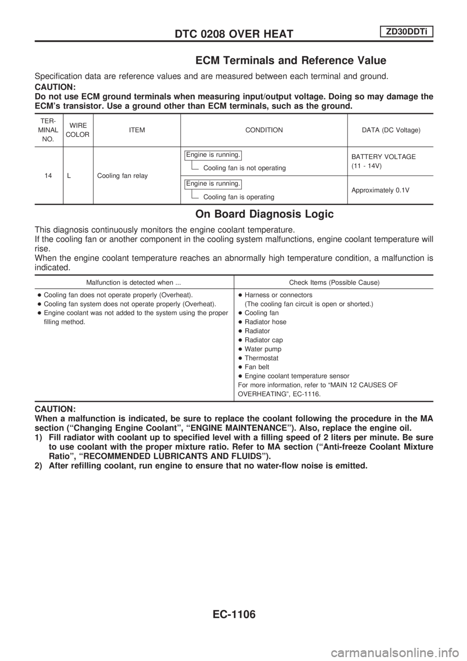
ECM Terminals and Reference Value
Specification data are reference values and are measured between each terminal and ground.
CAUTION:
Do not use ECM ground terminals when measuring input/output voltage. Doing so may damage the
ECM's transistor. Use a ground other than ECM terminals, such as the ground.
TER-
MINAL
NO.WIRE
COLORITEM CONDITION DATA (DC Voltage)
14 L Cooling fan relayEngine is running.
Cooling fan is not operatingBATTERY VOLTAGE
(11 - 14V)
Engine is running.
Cooling fan is operatingApproximately 0.1V
On Board Diagnosis Logic
This diagnosis continuously monitors the engine coolant temperature.
If the cooling fan or another component in the cooling system malfunctions, engine coolant temperature will
rise.
When the engine coolant temperature reaches an abnormally high temperature condition, a malfunction is
indicated.
Malfunction is detected when ... Check Items (Possible Cause)
+Cooling fan does not operate properly (Overheat).
+Cooling fan system does not operate properly (Overheat).
+Engine coolant was not added to the system using the proper
filling method.+Harness or connectors
(The cooling fan circuit is open or shorted.)
+Cooling fan
+Radiator hose
+Radiator
+Radiator cap
+Water pump
+Thermostat
+Fan belt
+Engine coolant temperature sensor
For more information, refer to ªMAIN 12 CAUSES OF
OVERHEATINGº, EC-1116.
CAUTION:
When a malfunction is indicated, be sure to replace the coolant following the procedure in the MA
section (ªChanging Engine Coolantº, ªENGINE MAINTENANCEº). Also, replace the engine oil.
1) Fill radiator with coolant up to specified level with a filling speed of 2 liters per minute. Be sure
to use coolant with the proper mixture ratio. Refer to MA section (ªAnti-freeze Coolant Mixture
Ratioº, ªRECOMMENDED LUBRICANTS AND FLUIDSº).
2) After refilling coolant, run engine to ensure that no water-flow noise is emitted.
DTC 0208 OVER HEATZD30DDTi
EC-1106
Page 340 of 1033
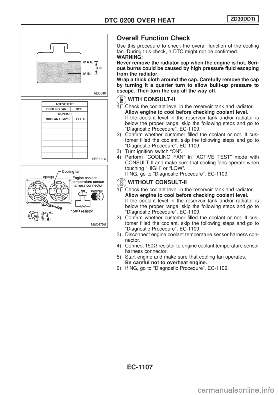
Overall Function Check
Use this procedure to check the overall function of the cooling
fan. During this check, a DTC might not be confirmed.
WARNING:
Never remove the radiator cap when the engine is hot. Seri-
ous burns could be caused by high pressure fluid escaping
from the radiator.
Wrap a thick cloth around the cap. Carefully remove the cap
by turning it a quarter turn to allow built-up pressure to
escape. Then turn the cap all the way off.
WITH CONSULT-II
1) Check the coolant level in the reservoir tank and radiator.
Allow engine to cool before checking coolant level.
If the coolant level in the reservoir tank and/or radiator is
below the proper range, skip the following steps and go to
ªDiagnostic Procedureº, EC-1109.
2) Confirm whether customer filled the coolant or not. If cus-
tomer filled the coolant, skip the following steps and go to
ªDiagnostic Procedureº, EC-1109.
3) Turn ignition switch ªONº.
4) Perform ªCOOLING FANº in ªACTIVE TESTº mode with
CONSULT-II and make sure that cooling fans operate when
touching ªHIGHº or ªLOWº.
If NG, go to ªDiagnostic Procedureº, EC-1109.
WITHOUT CONSULT-II
1) Check the coolant level in the reservoir tank and radiator.
Allow engine to cool before checking coolant level.
If the coolant level in the reservoir tank and/or radiator is
below the proper range, skip the following steps and go to
ªDiagnostic Procedureº, EC-1109.
2) Confirm whether customer filled the coolant or not. If cus-
tomer filled the coolant, skip the following steps and go to
ªDiagnostic Procedureº, EC-1109.
3) Disconnect engine coolant temperature sensor harness con-
nector.
4) Connect 150Wresistor to engine coolant temperature sensor
harness connector.
5) Start engine and make sure that cooling fan operates.
Be careful not to overheat engine.
6) If NG, go to ªDiagnostic Procedureº, EC-1109.
AEC640
SEF111X
MEC475B
DTC 0208 OVER HEATZD30DDTi
EC-1107
Page 342 of 1033
Diagnostic Procedure
1 INSPECTION START
Do you have CONSULT-II?
Yes or No
YescGO TO 2.
NocGO TO 3.
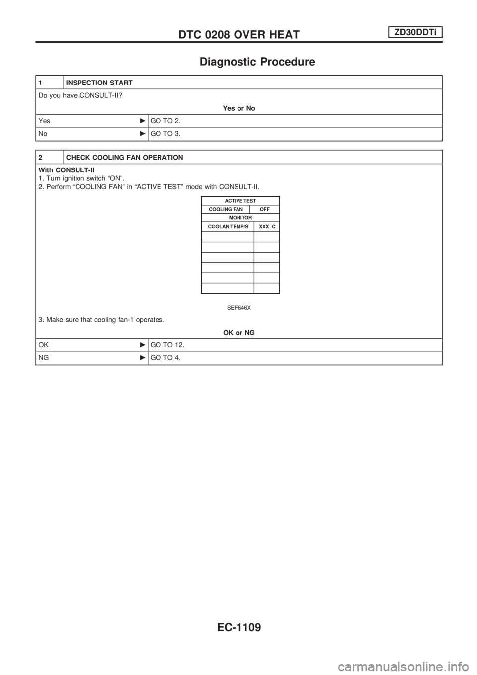
2 CHECK COOLING FAN OPERATION
With CONSULT-II
1. Turn ignition switch ªONº.
2. Perform ªCOOLING FANº in ªACTIVE TESTº mode with CONSULT-II.
SEF646X
3. Make sure that cooling fan-1 operates.
OK or NG
OKcGO TO 12.
NGcGO TO 4.
DTC 0208 OVER HEATZD30DDTi
EC-1109
Page 343 of 1033
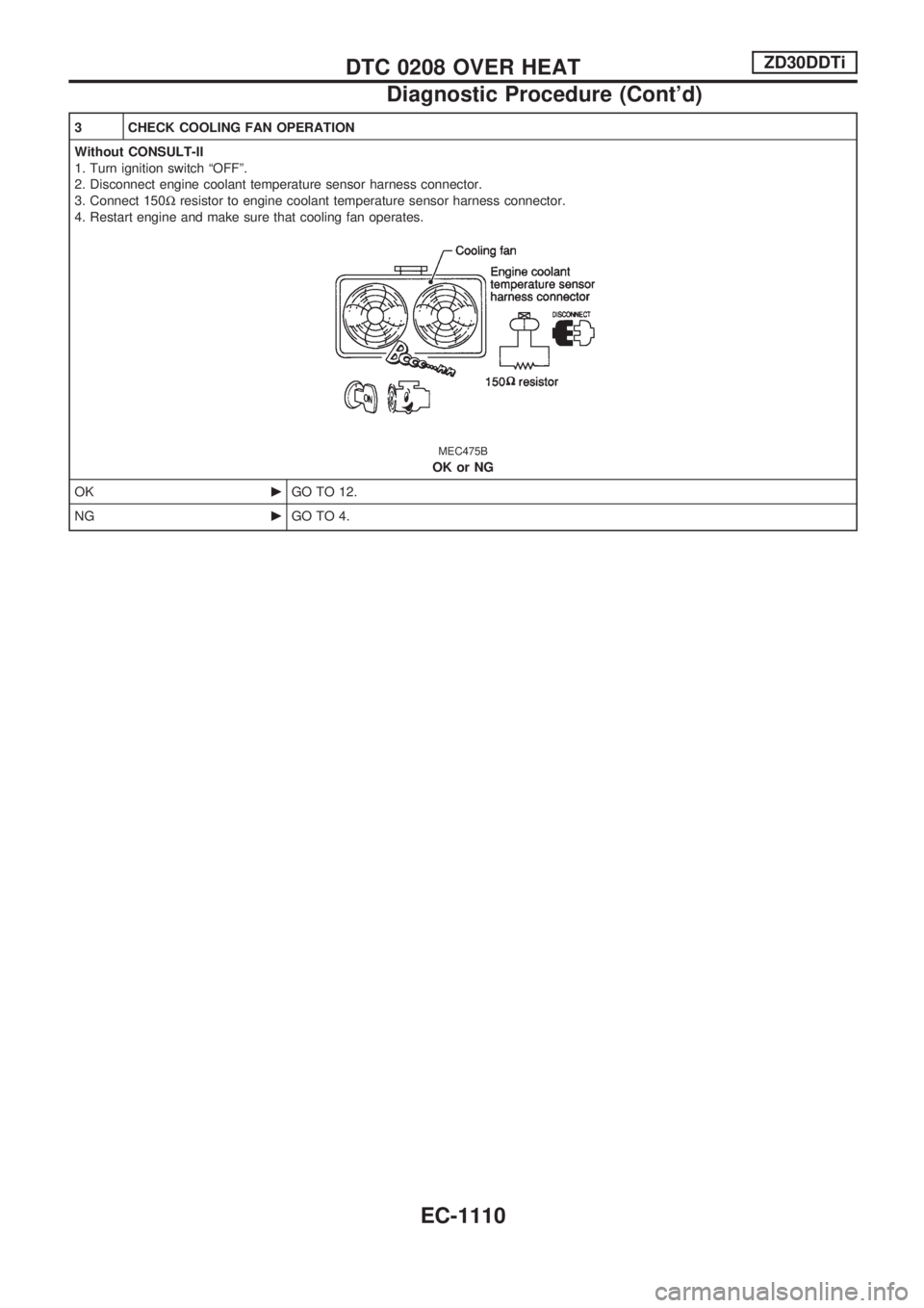
3 CHECK COOLING FAN OPERATION
Without CONSULT-II
1. Turn ignition switch ªOFFº.
2. Disconnect engine coolant temperature sensor harness connector.
3. Connect 150Wresistor to engine coolant temperature sensor harness connector.
4. Restart engine and make sure that cooling fan operates.
MEC475B
OK or NG
OKcGO TO 12.
NGcGO TO 4.
DTC 0208 OVER HEATZD30DDTi
Diagnostic Procedure (Cont'd)
EC-1110
Page 344 of 1033
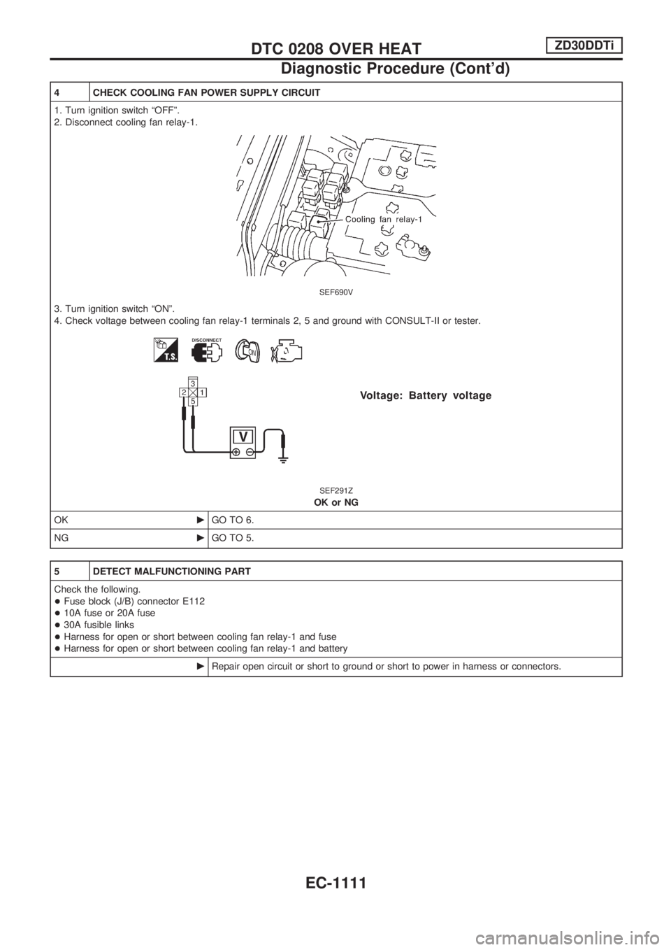
4 CHECK COOLING FAN POWER SUPPLY CIRCUIT
1. Turn ignition switch ªOFFº.
2. Disconnect cooling fan relay-1.
SEF690V
3. Turn ignition switch ªONº.
4. Check voltage between cooling fan relay-1 terminals 2, 5 and ground with CONSULT-II or tester.
SEF291Z
OK or NG
OKcGO TO 6.
NGcGO TO 5.
5 DETECT MALFUNCTIONING PART
Check the following.
+Fuse block (J/B) connector E112
+10A fuse or 20A fuse
+30A fusible links
+Harness for open or short between cooling fan relay-1 and fuse
+Harness for open or short between cooling fan relay-1 and battery
cRepair open circuit or short to ground or short to power in harness or connectors.
DTC 0208 OVER HEATZD30DDTi
Diagnostic Procedure (Cont'd)
EC-1111