Page 345 of 1033
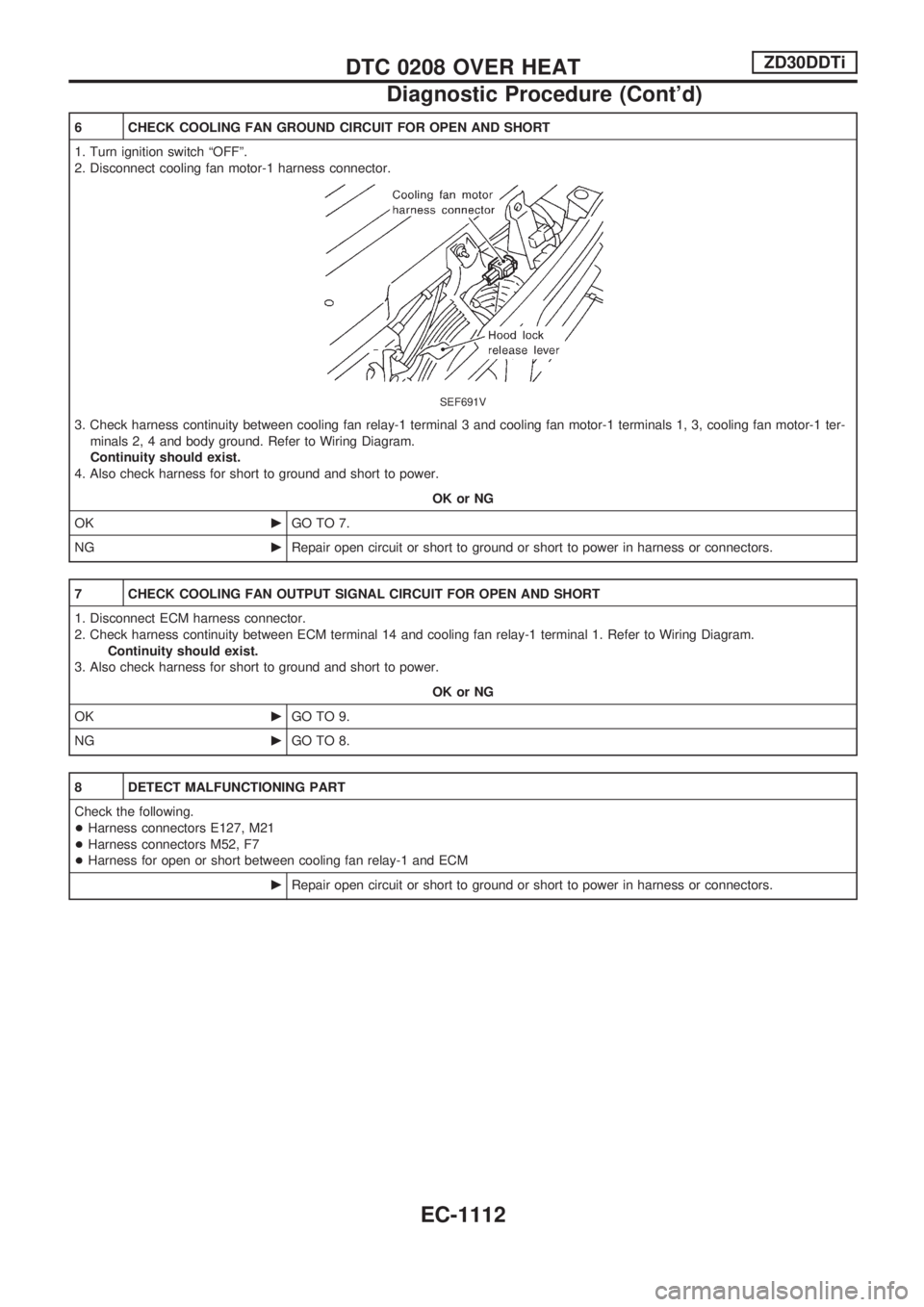
6 CHECK COOLING FAN GROUND CIRCUIT FOR OPEN AND SHORT
1. Turn ignition switch ªOFFº.
2. Disconnect cooling fan motor-1 harness connector.
SEF691V
3. Check harness continuity between cooling fan relay-1 terminal 3 and cooling fan motor-1 terminals 1, 3, cooling fan motor-1 ter-
minals 2, 4 and body ground. Refer to Wiring Diagram.
Continuity should exist.
4. Also check harness for short to ground and short to power.
OK or NG
OKcGO TO 7.
NGcRepair open circuit or short to ground or short to power in harness or connectors.
7 CHECK COOLING FAN OUTPUT SIGNAL CIRCUIT FOR OPEN AND SHORT
1. Disconnect ECM harness connector.
2. Check harness continuity between ECM terminal 14 and cooling fan relay-1 terminal 1. Refer to Wiring Diagram.
Continuity should exist.
3. Also check harness for short to ground and short to power.
OK or NG
OKcGO TO 9.
NGcGO TO 8.
8 DETECT MALFUNCTIONING PART
Check the following.
+Harness connectors E127, M21
+Harness connectors M52, F7
+Harness for open or short between cooling fan relay-1 and ECM
cRepair open circuit or short to ground or short to power in harness or connectors.
DTC 0208 OVER HEATZD30DDTi
Diagnostic Procedure (Cont'd)
EC-1112
Page 346 of 1033
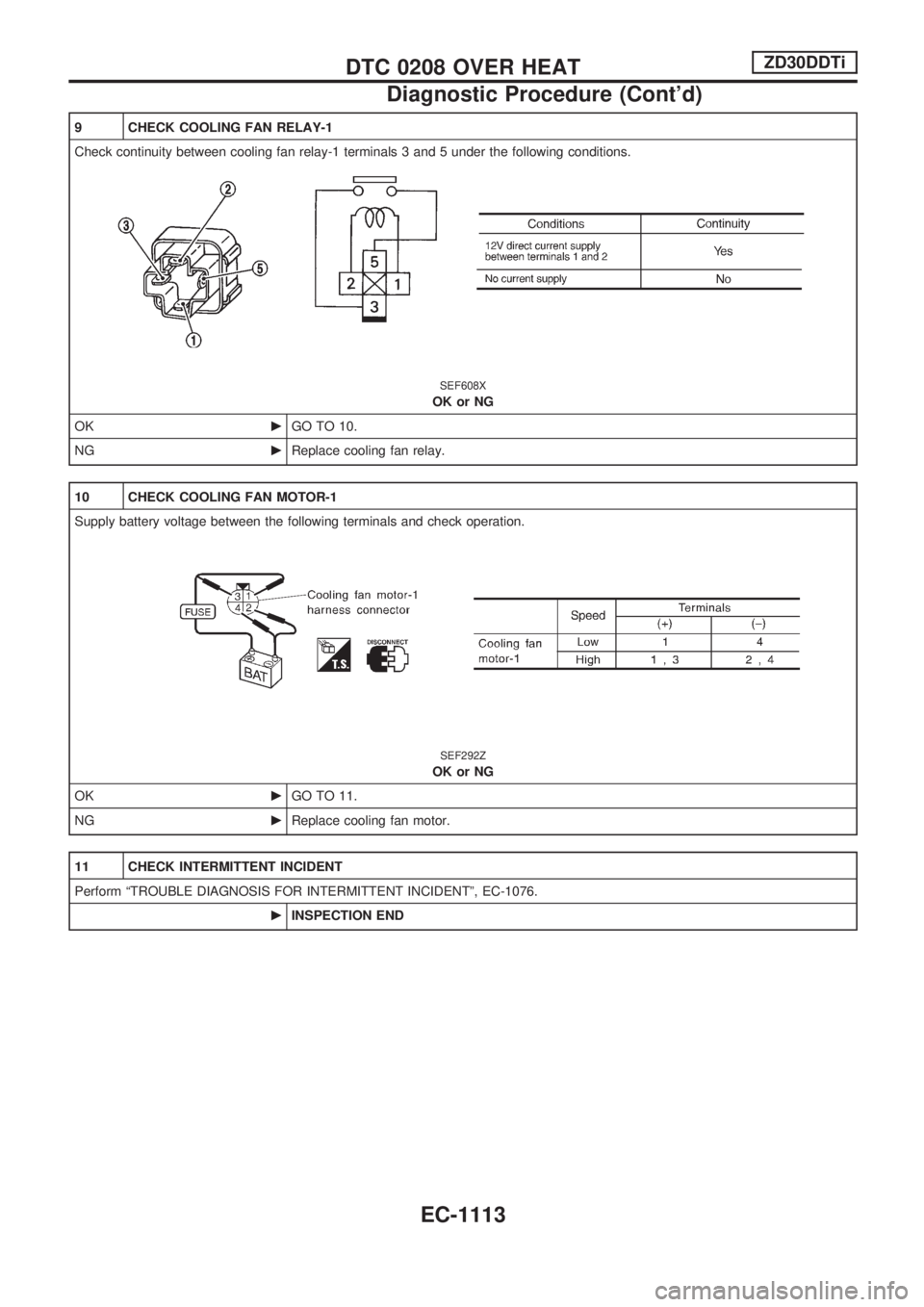
9 CHECK COOLING FAN RELAY-1
Check continuity between cooling fan relay-1 terminals 3 and 5 under the following conditions.
SEF608X
OK or NG
OKcGO TO 10.
NGcReplace cooling fan relay.
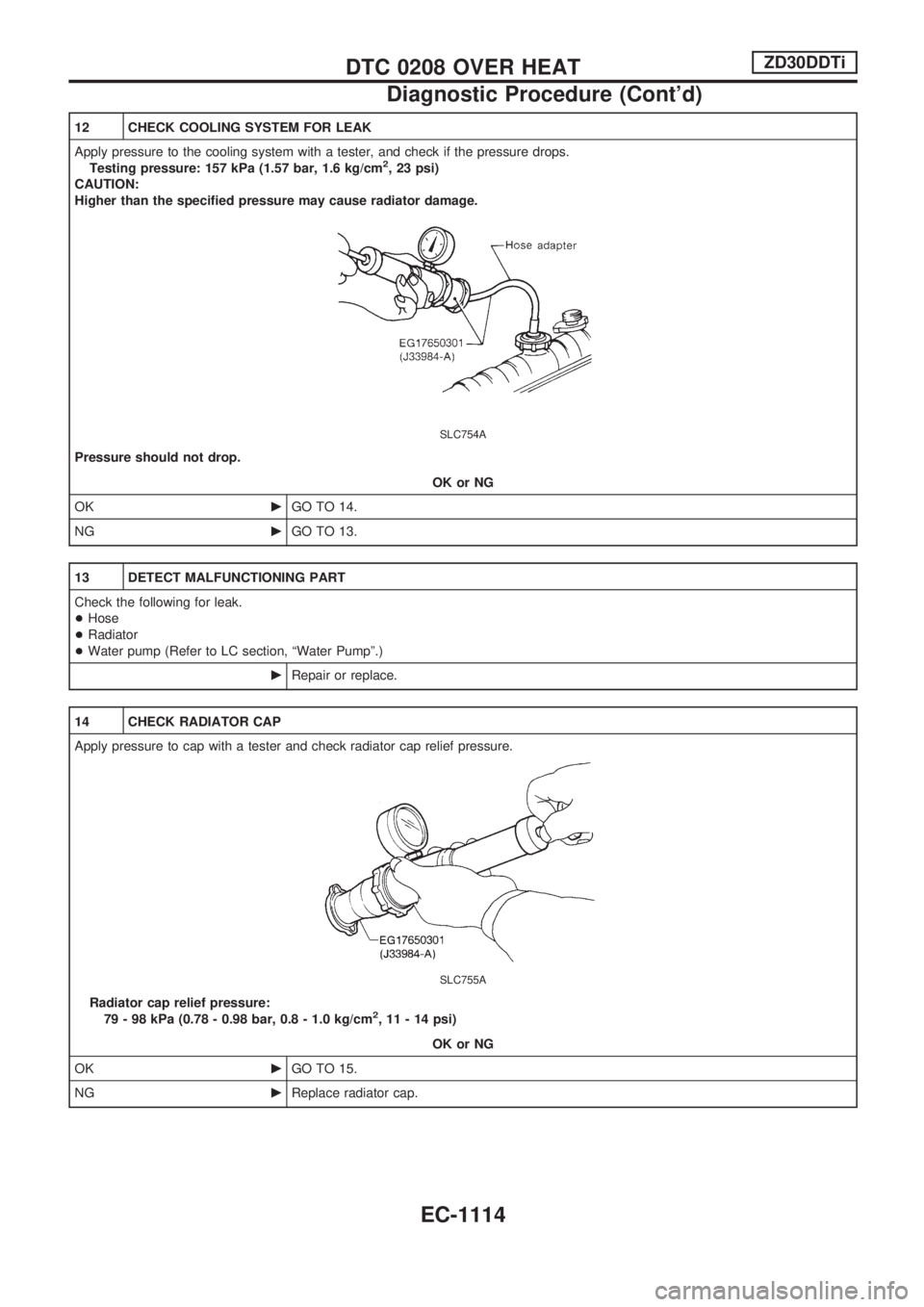
10 CHECK COOLING FAN MOTOR-1
Supply battery voltage between the following terminals and check operation.
SEF292Z
OK or NG
OKcGO TO 11.
NGcReplace cooling fan motor.
11 CHECK INTERMITTENT INCIDENT
Perform ªTROUBLE DIAGNOSIS FOR INTERMITTENT INCIDENTº, EC-1076.
cINSPECTION END
DTC 0208 OVER HEATZD30DDTi
Diagnostic Procedure (Cont'd)
EC-1113
Page 347 of 1033
12 CHECK COOLING SYSTEM FOR LEAK
Apply pressure to the cooling system with a tester, and check if the pressure drops.
Testing pressure: 157 kPa (1.57 bar, 1.6 kg/cm
2, 23 psi)
CAUTION:
Higher than the specified pressure may cause radiator damage.
SLC754A
Pressure should not drop.
OK or NG
OKcGO TO 14.
NGcGO TO 13.
13 DETECT MALFUNCTIONING PART
Check the following for leak.
+Hose
+Radiator
+Water pump (Refer to LC section, ªWater Pumpº.)
cRepair or replace.
14 CHECK RADIATOR CAP
Apply pressure to cap with a tester and check radiator cap relief pressure.
SLC755A
Radiator cap relief pressure:
79 - 98 kPa (0.78 - 0.98 bar, 0.8 - 1.0 kg/cm2, 11 - 14 psi)
OK or NG
OKcGO TO 15.
NGcReplace radiator cap.
DTC 0208 OVER HEATZD30DDTi
Diagnostic Procedure (Cont'd)
EC-1114
Page 349 of 1033
17 CHECK MAIN 12 CAUSES
If the cause cannot be isolated, go to ªMAIN 12 CAUSES OF OVERHEATINGº, EC-1116.
cINSPECTION END
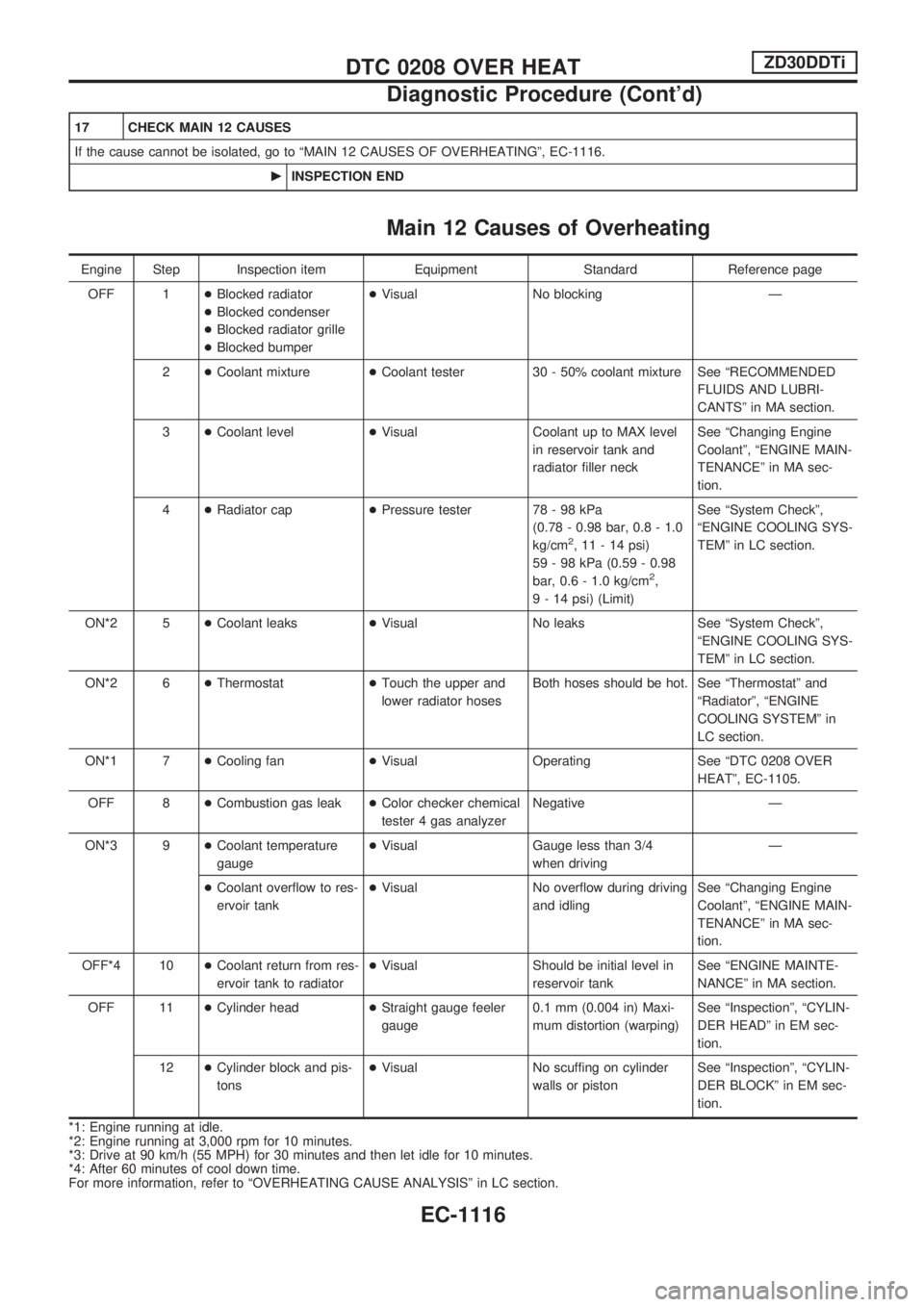
Main 12 Causes of Overheating
Engine Step Inspection item Equipment Standard Reference page
OFF 1+Blocked radiator
+Blocked condenser
+Blocked radiator grille
+Blocked bumper+Visual No blocking Ð
2+Coolant mixture+Coolant tester 30 - 50% coolant mixture See ªRECOMMENDED
FLUIDS AND LUBRI-
CANTSº in MA section.
3+Coolant level+Visual Coolant up to MAX level
in reservoir tank and
radiator filler neckSee ªChanging Engine
Coolantº, ªENGINE MAIN-
TENANCEº in MA sec-
tion.
4+Radiator cap+Pressure tester 78 - 98 kPa
(0.78 - 0.98 bar, 0.8 - 1.0
kg/cm
2, 11 - 14 psi)
59 - 98 kPa (0.59 - 0.98
bar, 0.6 - 1.0 kg/cm
2,
9 - 14 psi) (Limit)See ªSystem Checkº,
ªENGINE COOLING SYS-
TEMº in LC section.
ON*2 5+Coolant leaks+Visual No leaks See ªSystem Checkº,
ªENGINE COOLING SYS-
TEMº in LC section.
ON*2 6+Thermostat+Touch the upper and
lower radiator hosesBoth hoses should be hot. See ªThermostatº and
ªRadiatorº, ªENGINE
COOLING SYSTEMº in
LC section.
ON*1 7+Cooling fan+Visual Operating See ªDTC 0208 OVER
HEATº, EC-1105.
OFF 8+Combustion gas leak+Color checker chemical
tester 4 gas analyzerNegative Ð
ON*3 9+Coolant temperature
gauge+Visual Gauge less than 3/4
when drivingÐ
+Coolant overflow to res-
ervoir tank+Visual No overflow during driving
and idlingSee ªChanging Engine
Coolantº, ªENGINE MAIN-
TENANCEº in MA sec-
tion.
OFF*4 10+Coolant return from res-
ervoir tank to radiator+Visual Should be initial level in
reservoir tankSee ªENGINE MAINTE-
NANCEº in MA section.
OFF 11+Cylinder head+Straight gauge feeler
gauge0.1 mm (0.004 in) Maxi-
mum distortion (warping)See ªInspectionº, ªCYLIN-
DER HEADº in EM sec-
tion.
12+Cylinder block and pis-
tons+Visual No scuffing on cylinder
walls or pistonSee ªInspectionº, ªCYLIN-
DER BLOCKº in EM sec-
tion.
*1: Engine running at idle.
*2: Engine running at 3,000 rpm for 10 minutes.
*3: Drive at 90 km/h (55 MPH) for 30 minutes and then let idle for 10 minutes.
*4: After 60 minutes of cool down time.
For more information, refer to ªOVERHEATING CAUSE ANALYSISº in LC section.
DTC 0208 OVER HEATZD30DDTi
Diagnostic Procedure (Cont'd)
EC-1116
Page 737 of 1033
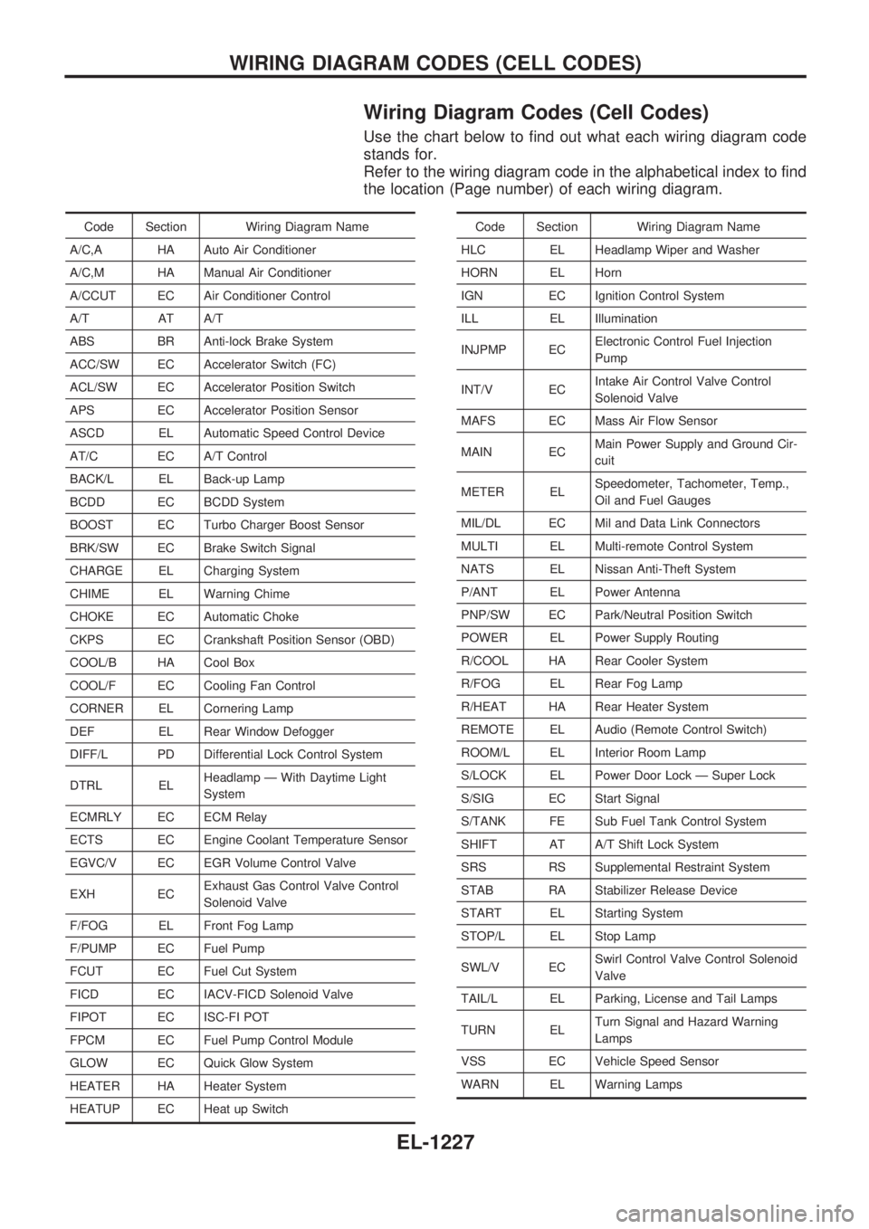
Wiring Diagram Codes (Cell Codes)
Use the chart below to find out what each wiring diagram code
stands for.
Refer to the wiring diagram code in the alphabetical index to find
the location (Page number) of each wiring diagram.
Code Section Wiring Diagram Name
A/C,A HA Auto Air Conditioner
A/C,M HA Manual Air Conditioner
A/CCUT EC Air Conditioner Control
A/T AT A/T
ABS BR Anti-lock Brake System
ACC/SW EC Accelerator Switch (FC)
ACL/SW EC Accelerator Position Switch
APS EC Accelerator Position Sensor
ASCD EL Automatic Speed Control Device
AT/C EC A/T Control
BACK/L EL Back-up Lamp
BCDD EC BCDD System
BOOST EC Turbo Charger Boost Sensor
BRK/SW EC Brake Switch Signal
CHARGE EL Charging System
CHIME EL Warning Chime
CHOKE EC Automatic Choke
CKPS EC Crankshaft Position Sensor (OBD)
COOL/B HA Cool Box
COOL/F EC Cooling Fan Control
CORNER EL Cornering Lamp
DEF EL Rear Window Defogger
DIFF/L PD Differential Lock Control System
DTRL ELHeadlamp Ð With Daytime Light
System
ECMRLY EC ECM Relay
ECTS EC Engine Coolant Temperature Sensor
EGVC/V EC EGR Volume Control Valve
EXH ECExhaust Gas Control Valve Control
Solenoid Valve
F/FOG EL Front Fog Lamp
F/PUMP EC Fuel Pump
FCUT EC Fuel Cut System
FICD EC IACV-FICD Solenoid Valve
FIPOT EC ISC-FI POT
FPCM EC Fuel Pump Control Module
GLOW EC Quick Glow System
HEATER HA Heater System
HEATUP EC Heat up SwitchCode Section Wiring Diagram Name
HLC EL Headlamp Wiper and Washer
HORN EL Horn
IGN EC Ignition Control System
ILL EL Illumination
INJPMP ECElectronic Control Fuel Injection
Pump
INT/V ECIntake Air Control Valve Control
Solenoid Valve
MAFS EC Mass Air Flow Sensor
MAIN ECMain Power Supply and Ground Cir-
cuit
METER ELSpeedometer, Tachometer, Temp.,
Oil and Fuel Gauges
MIL/DL EC Mil and Data Link Connectors
MULTI EL Multi-remote Control System
NATS EL Nissan Anti-Theft System
P/ANT EL Power Antenna
PNP/SW EC Park/Neutral Position Switch
POWER EL Power Supply Routing
R/COOL HA Rear Cooler System
R/FOG EL Rear Fog Lamp
R/HEAT HA Rear Heater System
REMOTE EL Audio (Remote Control Switch)
ROOM/L EL Interior Room Lamp
S/LOCK EL Power Door Lock Ð Super Lock
S/SIG EC Start Signal
S/TANK FE Sub Fuel Tank Control System
SHIFT AT A/T Shift Lock System
SRS RS Supplemental Restraint System
STAB RA Stabilizer Release Device
START EL Starting System
STOP/L EL Stop Lamp
SWL/V ECSwirl Control Valve Control Solenoid
Valve
TAIL/L EL Parking, License and Tail Lamps
TURN ELTurn Signal and Hazard Warning
Lamps
VSS EC Vehicle Speed Sensor
WARN EL Warning Lamps
WIRING DIAGRAM CODES (CELL CODES)
EL-1227
Page 747 of 1033
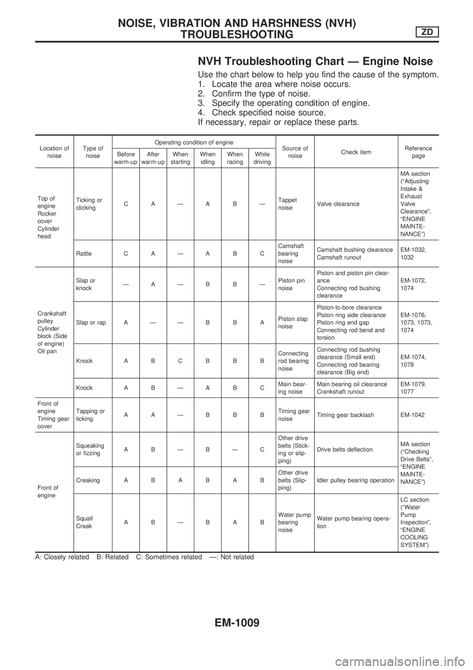
NVH Troubleshooting Chart Ð Engine Noise
Use the chart below to help you find the cause of the symptom.
1. Locate the area where noise occurs.
2. Confirm the type of noise.
3. Specify the operating condition of engine.
4. Check specified noise source.
If necessary, repair or replace these parts.
Location of
noiseType of
noiseOperating condition of engine
Source of
noiseCheck itemReference
page Before
warm-upAfter
warm-upWhen
startingWhen
idlingWhen
racingWhile
driving
Top of
engine
Rocker
cover
Cylinder
headTicking or
clickingCAÐABÐTappet
noiseValve clearanceMA section
(ªAdjusting
Intake &
Exhaust
Valve
Clearanceº,
ªENGINE
MAINTE-
NANCEº)
Rattle C A Ð A B CCamshaft
bearing
noiseCamshaft bushing clearance
Camshaft runoutEM-1032,
1032
Crankshaft
pulley
Cylinder
block (Side
of engine)
Oil panSlap or
knockÐAÐB BÐPiston pin
noisePiston and piston pin clear-
ance
Connecting rod bushing
clearanceEM-1072,
1074
Slap or rap A Ð Ð B B APiston slap
noisePiston-to-bore clearance
Piston ring side clearance
Piston ring end gap
Connecting rod bend and
torsionEM-1076,
1073, 1073,
1074
Knock A B C B B BConnecting
rod bearing
noiseConnecting rod bushing
clearance (Small end)
Connecting rod bearing
clearance (Big end)EM-1074,
1078
Knock A B Ð A B CMain bear-
ing noiseMain bearing oil clearance
Crankshaft runoutEM-1079,
1077
Front of
engine
Timing gear
coverTapping or
tickingAAÐBBBTiming gear
noiseTiming gear backlash EM-1042
Front of
engineSqueaking
or fizzingABÐBÐCOther drive
belts (Stick-
ing or slip-
ping)Drive belts deflectionMA section
(ªChecking
Drive Beltsº,
ªENGINE
MAINTE-
NANCEº) CreakingABABABOther drive
belts (Slip-
ping)Idler pulley bearing operation
Squall
CreakABÐBABWater pump
bearing
noiseWater pump bearing opera-
tionLC section
(ªWater
Pump
Inspectionº,
ªENGINE
COOLING
SYSTEMº)
A: Closely related B: Related C: Sometimes related Ð: Not related
NOISE, VIBRATION AND HARSHNESS (NVH)
TROUBLESHOOTINGZD
EM-1009
Page 763 of 1033
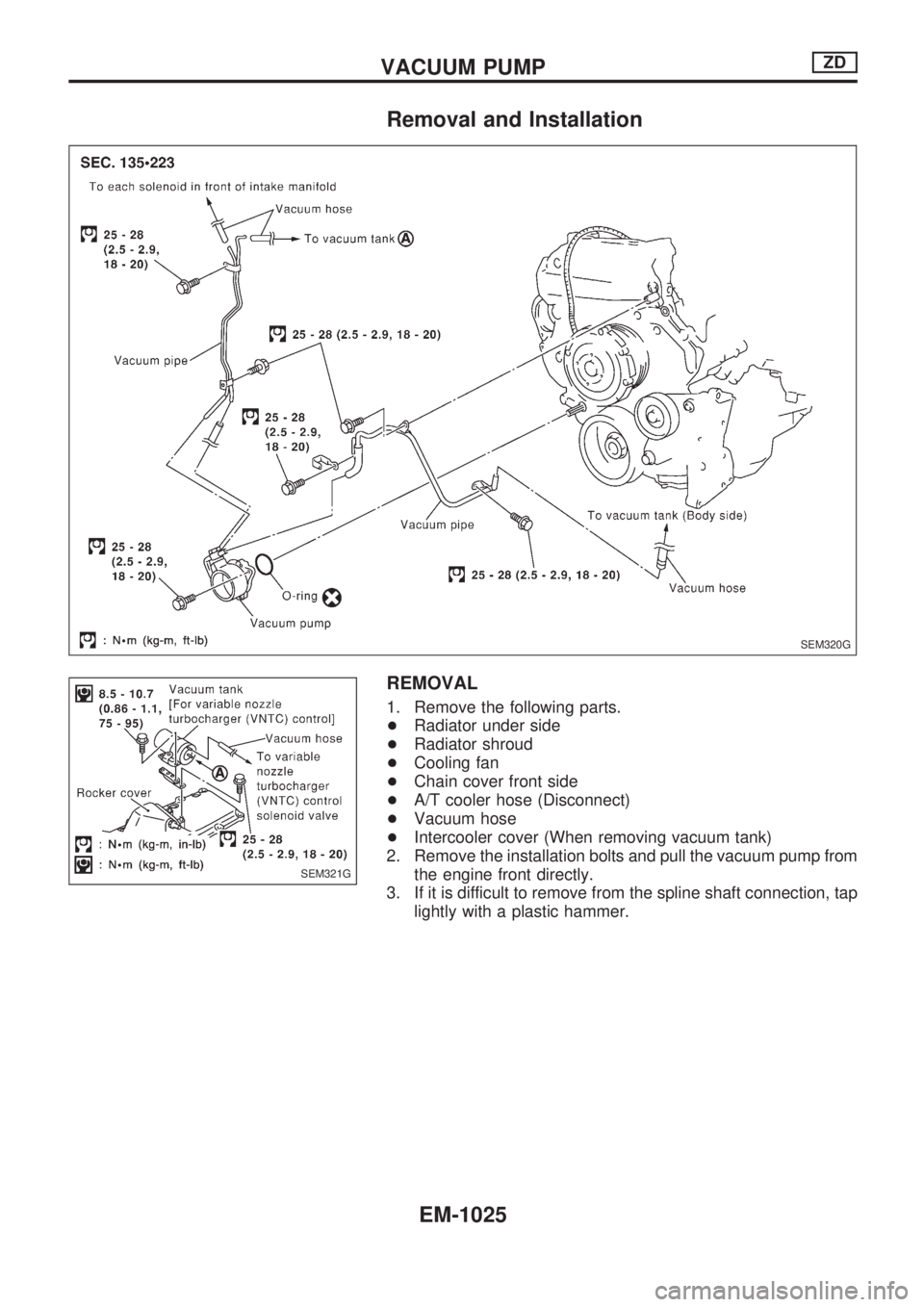
Removal and Installation
REMOVAL
1. Remove the following parts.
+Radiator under side
+Radiator shroud
+Cooling fan
+Chain cover front side
+A/T cooler hose (Disconnect)
+Vacuum hose
+Intercooler cover (When removing vacuum tank)
2. Remove the installation bolts and pull the vacuum pump from
the engine front directly.
3. If it is difficult to remove from the spline shaft connection, tap
lightly with a plastic hammer.
SEM320G
SEM321G
VACUUM PUMPZD
EM-1025
Page 765 of 1033
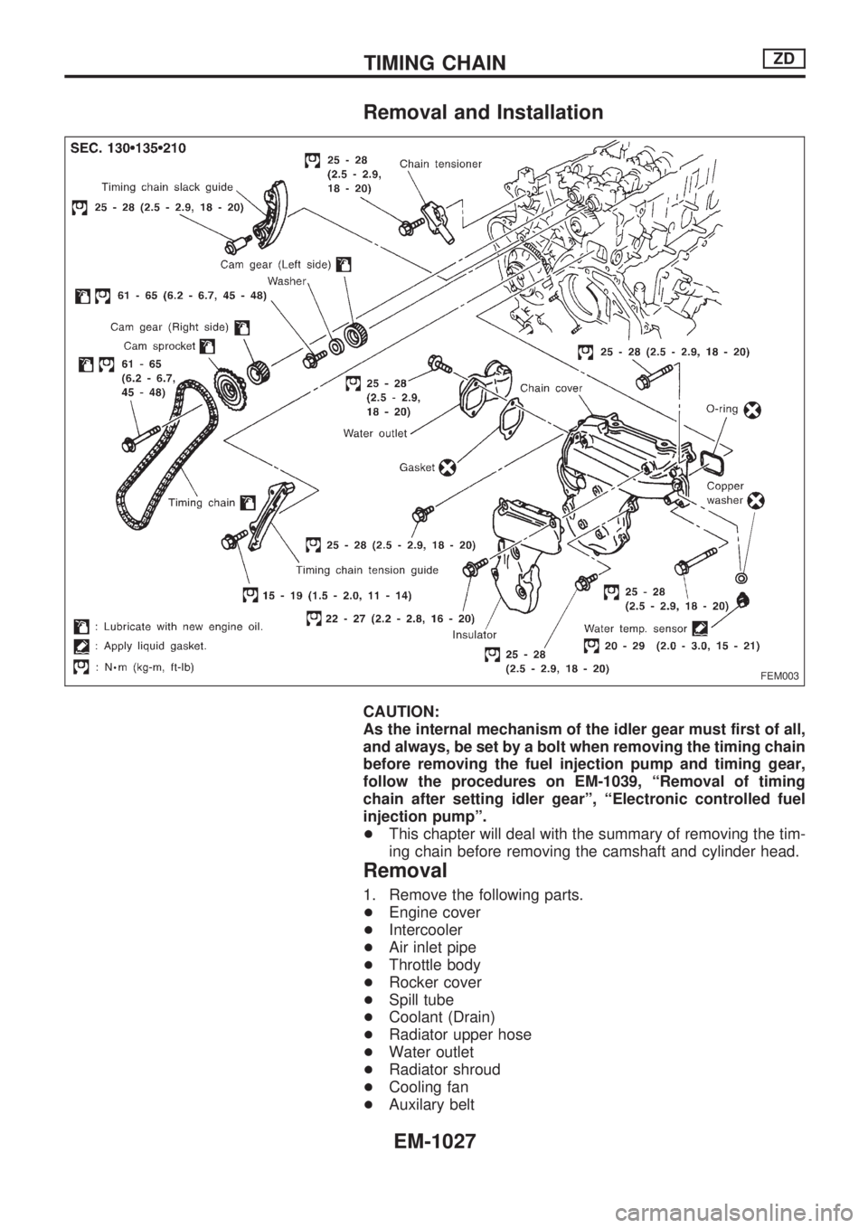
Removal and Installation
CAUTION:
As the internal mechanism of the idler gear must first of all,
and always, be set by a bolt when removing the timing chain
before removing the fuel injection pump and timing gear,
follow the procedures on EM-1039, ªRemoval of timing
chain after setting idler gearº, ªElectronic controlled fuel
injection pumpº.
+This chapter will deal with the summary of removing the tim-
ing chain before removing the camshaft and cylinder head.
Removal
1. Remove the following parts.
+Engine cover
+Intercooler
+Air inlet pipe
+Throttle body
+Rocker cover
+Spill tube
+Coolant (Drain)
+Radiator upper hose
+Water outlet
+Radiator shroud
+Cooling fan
+Auxilary belt
FEM003
TIMING CHAINZD
EM-1027