Page 582 of 1033
Trouble Diagnoses
DIAGNOSTIC PROCEDURE
SYMPTOM: Front interior room lamp does not turn on when
any door is opened, or timer does not operate
properly.
Does room lamp turn on when room lamp
switch is in ªONº position?
Yes
cNo
Check the following.
+Bulb
+10A fuse [No.
20,
located in the fuse block
(J/B)]
+Harness for open or
short between fuse and
front interior room lamp
+Front interior room lamp
ground condition
Does key warning chime operate prop-
erly?
Yes
cNo
Check ªWARNING
CHIMEº system.
(Refer to EL-1094.)
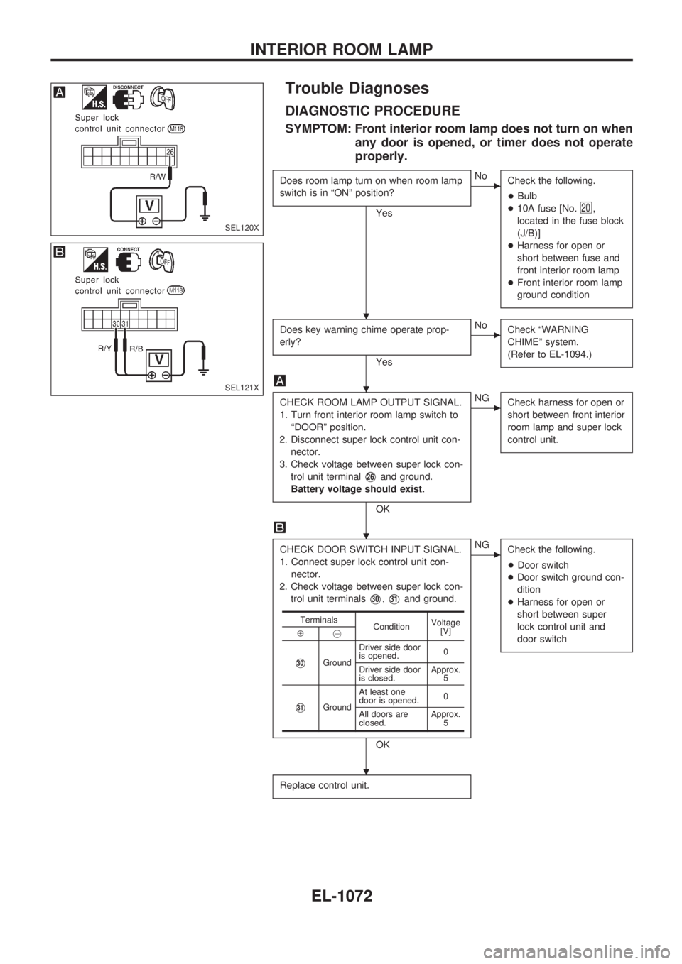
CHECK ROOM LAMP OUTPUT SIGNAL.
1. Turn front interior room lamp switch to
ªDOORº position.
2. Disconnect super lock control unit con-
nector.
3. Check voltage between super lock con-
trol unit terminal
V26and ground.
Battery voltage should exist.
OK
cNG
Check harness for open or
short between front interior
room lamp and super lock
control unit.
CHECK DOOR SWITCH INPUT SIGNAL.
1. Connect super lock control unit con-
nector.
2. Check voltage between super lock con-
trol unit terminals
V30,V31and ground.
OK
cNG
Check the following.
+Door switch
+Door switch ground con-
dition
+Harness for open or
short between super
lock control unit and
door switch
Replace control unit.
Terminals
ConditionVoltage
[V]
Å@
V30GroundDriver side door
is opened.0
Driver side door
is closed.Approx.
5
V31GroundAt least one
door is opened.0
All doors are
closed.Approx.
5
SEL120X
SEL121X
.
.
.
.
INTERIOR ROOM LAMP
EL-1072
Page 616 of 1033
Trouble Diagnoses
SYMPTOM: Rear window defogger does not activate, or
does not go off after activating.
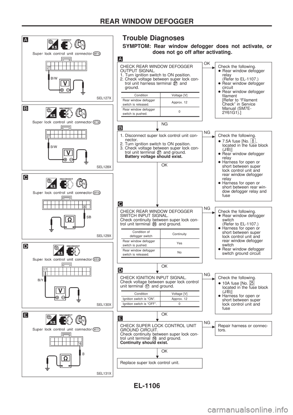
CHECK REAR WINDOW DEFOGGER
OUTPUT SIGNAL.
1. Turn ignition switch to ON position.
2. Check voltage between super lock con-
trol unit harness terminal
V27and
ground.
NG
cOK
Check the following.
+Rear window defogger
relay
(Refer to EL-1107.)
+Rear window defogger
circuit
+Rear window defogger
filament
[Refer to ªFilament
Checkº in Service
Manual (SM7E-
2Y61G1).]
1. Disconnect super lock control unit con-
nector.
2. Turn ignition switch to ON position.
3. Check voltage between super lock con-
trol unit terminal
V27and ground.
Battery voltage should exist.
OK
cNG
Check the following.
+7.5A fuse [No.
8,
located in the fuse block
(J/B)]
+Rear window defogger
relay
+Harness for open or
short between super
lock control unit and
rear window defogger
relay
+Harness for open or
short between rear win-
dow defogger relay and
fuse
CHECK REAR WINDOW DEFOGGER
SWITCH INPUT SIGNAL.
Check continuity between super lock con-
trol unit terminal
V35and ground.
OK
cNG
Check the following.
+Rear window defogger
switch
(Refer to EL-1107.)
+Harness for open or
short between super
lock control unit and
rear window defogger
switch
+Rear window defogger
switch ground circuit
CHECK IGNITION INPUT SIGNAL.
Check voltage between super lock control
unit terminal
V17and ground.
OK
cNG
Check the following.
+10A fuse [No.
25located in the fuse block
(J/B)]
+Harness for open or
short between super
lock control unit and
fuse
CHECK SUPER LOCK CONTROL UNIT
GROUND CIRCUIT.
Check continuity between super lock con-
trol unit terminal
V16and ground.
Continuity should exist.
OK
cNG
Repair harness or connec-
tors.
Replace super lock control unit.
Condition Voltage [V]
Rear window defogger
switch is released.Approx. 12
Rear window defogger
switch is pushed.0
Condition of
defogger switchContinuity
Rear window defogger
switch is pushed.Yes
Rear window defogger
switch is released.No
Condition Voltage [V]
Ignition switch is ªONº. Approx. 12
Ignition switch is ªOFFº. 0
SEL127X
SEL128X
SEL129X
SEL130X
SEL131X
.
.
.
.
.
REAR WINDOW DEFOGGER
EL-1106
Page 632 of 1033
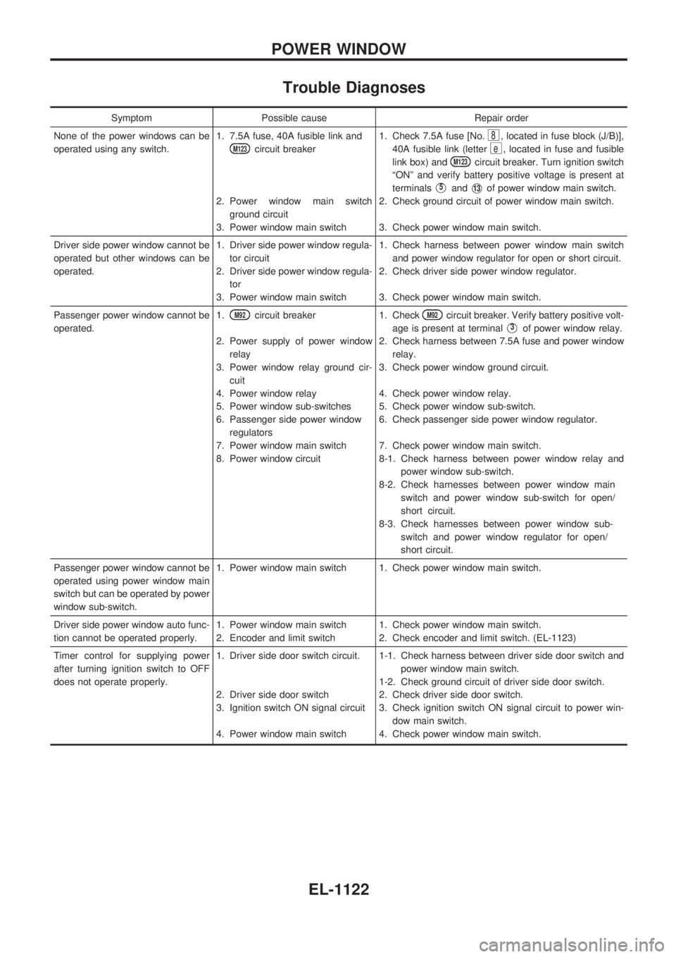
Trouble Diagnoses
Symptom Possible cause Repair order
None of the power windows can be
operated using any switch.1. 7.5A fuse, 40A fusible link and
M123circuit breaker
2. Power window main switch
ground circuit
3. Power window main switch1. Check 7.5A fuse [No.
8, located in fuse block (J/B)],
40A fusible link (letter
e, located in fuse and fusible
link box) and
M123circuit breaker. Turn ignition switch
ªONº and verify battery positive voltage is present at
terminals
V5andV13of power window main switch.
2. Check ground circuit of power window main switch.
3. Check power window main switch.
Driver side power window cannot be
operated but other windows can be
operated.1. Driver side power window regula-
tor circuit
2. Driver side power window regula-
tor
3. Power window main switch1. Check harness between power window main switch
and power window regulator for open or short circuit.
2. Check driver side power window regulator.
3. Check power window main switch.
Passenger power window cannot be
operated.1.
M92circuit breaker
2. Power supply of power window
relay
3. Power window relay ground cir-
cuit
4. Power window relay
5. Power window sub-switches
6. Passenger side power window
regulators
7. Power window main switch
8. Power window circuit1. CheckM92circuit breaker. Verify battery positive volt-
age is present at terminal
V3of power window relay.
2. Check harness between 7.5A fuse and power window
relay.
3. Check power window ground circuit.
4. Check power window relay.
5. Check power window sub-switch.
6. Check passenger side power window regulator.
7. Check power window main switch.
8-1. Check harness between power window relay and
power window sub-switch.
8-2. Check harnesses between power window main
switch and power window sub-switch for open/
short circuit.
8-3. Check harnesses between power window sub-
switch and power window regulator for open/
short circuit.
Passenger power window cannot be
operated using power window main
switch but can be operated by power
window sub-switch.1. Power window main switch 1. Check power window main switch.
Driver side power window auto func-
tion cannot be operated properly.1. Power window main switch
2. Encoder and limit switch1. Check power window main switch.
2. Check encoder and limit switch. (EL-1123)
Timer control for supplying power
after turning ignition switch to OFF
does not operate properly.1. Driver side door switch circuit.
2. Driver side door switch
3. Ignition switch ON signal circuit
4. Power window main switch1-1. Check harness between driver side door switch and
power window main switch.
1-2. Check ground circuit of driver side door switch.
2. Check driver side door switch.
3. Check ignition switch ON signal circuit to power win-
dow main switch.
4. Check power window main switch.
POWER WINDOW
EL-1122
Page 636 of 1033
Key reminder system
+If the ignition key is in the ignition key cylinder and the driver door is open, setting lock knob on driver door,
key or multi-remote controller to ªLOCKº locks the door once but then immediately unlocks all doors. (Sig-
nal from unlock sensor driver side)
System initialization
+System initialization is required when battery cables are reconnected. Conduct one of the followings to
release super lock once;
Ð insert the key into ignition key cylinder and turn it to ON.
Ð LOCK/UNLOCK operation using door key cylinder or multi-remote controller.
POWER DOOR LOCK Ð Super Lock Ð
System Description (Cont'd)
EL-1126
Page 650 of 1033
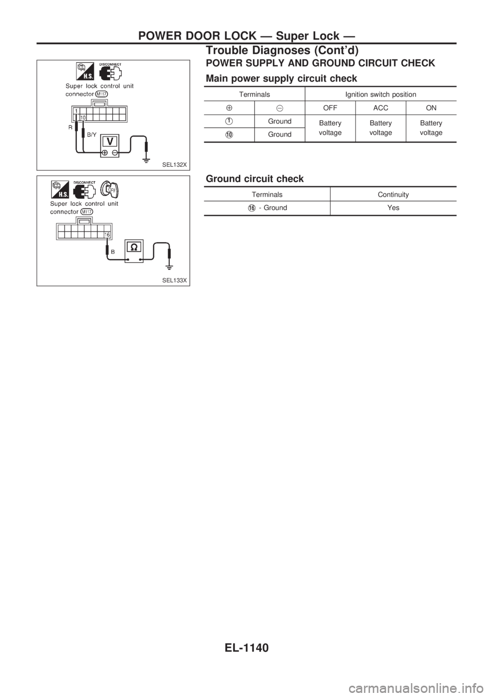
POWER SUPPLY AND GROUND CIRCUIT CHECK
Main power supply circuit check
Terminals Ignition switch position
Å@OFF ACC ON
V1Ground
Battery
voltageBattery
voltageBattery
voltage
V10Ground
Ground circuit check
Terminals Continuity
V16- Ground Yes
SEL132X
SEL133X
POWER DOOR LOCK Ð Super Lock Ð
Trouble Diagnoses (Cont'd)
EL-1140
Page 653 of 1033
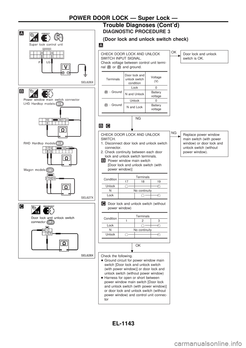
DIAGNOSTIC PROCEDURE 3
(Door lock and unlock switch check)
CHECK DOOR LOCK AND UNLOCK
SWITCH INPUT SIGNAL.
Check voltage between control unit termi-
nal
V20orV23and ground.
NG
cOK
Door lock and unlock
switch is OK.
CHECK DOOR LOCK AND UNLOCK
SWITCH.
1. Disconnect door lock and unlock switch
connector.
2. Check continuity between each door
lock and unlock switch terminals.
Power window main switch
[Door lock and unlock switch (with
power window)]
Door lock and unlock switch (without
power window)
OK
cNG
Replace power window
main switch (with power
window) or door lock and
unlock switch (without
power window).
Check the following.
+Ground circuit for power window main
switch [Door lock and unlock switch
(with power window)] or door lock and
unlock switch (without power window)
+Harness for open or short between
power window main switch [Door lock
and unlock switch (with power window)]
or door lock and unlock switch (without
power window) and control unit connec-
tor
TerminalsDoor lock and
unlock switch
conditionVoltage
(V)
V20- GroundLock 0
N and UnlockBattery
voltage
V23- GroundUnlock 0
N and LockBattery
voltage
ConditionTerminals17 18 19
Unlockjj
N No continuity
Lockjj
ConditionTerminals123
Lockjj
N No continuity
Unlockjj
SEL626X
SEL627X
SEL628X
.
.
POWER DOOR LOCK Ð Super Lock Ð
Trouble Diagnoses (Cont'd)
EL-1143
Page 654 of 1033
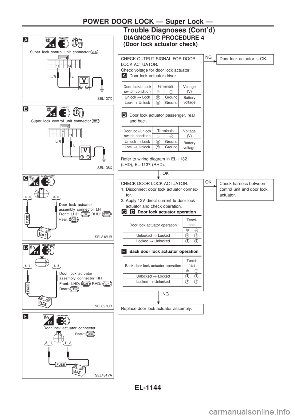
DIAGNOSTIC PROCEDURE 4
(Door lock actuator check)
CHECK OUTPUT SIGNAL FOR DOOR
LOCK ACTUATOR.
Check voltage for door lock actuator.
Door lock actuator driver
Door lock actuator passenger, rear
and back
Refer to wiring diagram in EL-1132
(LHD), EL-1137 (RHD).
OK
cNG
Door lock actuator is OK.
CHECK DOOR LOCK ACTUATOR.
1. Disconnect door lock actuator connec-
tor.
2. Apply 12V direct current to door lock
actuator and check operation.
Door lock actuator operation
Back door lock actuator operation
NG
cOK
Check harness between
control unit and door lock
actuator.
Replace door lock actuator assembly.
Door lock/unlock
switch conditionTerminals
Voltage
(V)
Å@
Unlock®Lock
V14Ground
Battery
voltage
Lock®Unlock
V11Ground
Door lock/unlock
switch conditionTerminals
Voltage
(V)
Å@
Unlock®Lock
V14Ground
Battery
voltage Lock®Unlock
V4Ground
Door lock actuator operationTermi-
nals
Å@
Unlocked®Locked
V6V3
Locked®UnlockedV3V6
Back door lock actuator operationTermi-
nals
Å@
Unlocked®Locked
V3V1
Locked®UnlockedV1V3
SEL137X
SEL138X
SEL818UB
SEL827UB
SEL434VA
.
.
POWER DOOR LOCK Ð Super Lock Ð
Trouble Diagnoses (Cont'd)
EL-1144
Page 658 of 1033
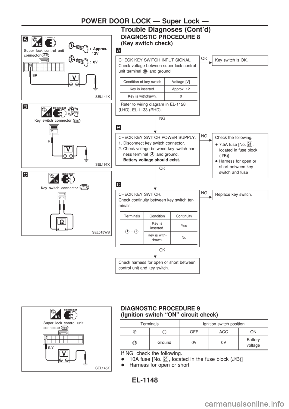
DIAGNOSTIC PROCEDURE 8
(Key switch check)
CHECK KEY SWITCH INPUT SIGNAL.
Check voltage between super lock control
unit terminal
V18and ground.
Refer to wiring diagram in EL-1128
(LHD), EL-1133 (RHD).
NG
cOK
Key switch is OK.
CHECK KEY SWITCH POWER SUPPLY.
1. Disconnect key switch connector.
2. Check voltage between key switch har-
ness terminal
V2and ground.
Battery voltage should exist.
OK
cNG
Check the following.
+7.5A fuse [No.
24,
located in fuse block
(J/B)]
+Harness for open or
short between key
switch and fuse
CHECK KEY SWITCH.
Check continuity between key switch ter-
minals.
OK
cNG
Replace key switch.
Check harness for open or short between
control unit and key switch.
Condition of key switch Voltage [V]
Key is inserted. Approx. 12
Key is withdrawn. 0
Terminals Condition Continuity
V1-V2
Key is
inserted.Yes
Key is with-
drawn.No
DIAGNOSTIC PROCEDURE 9
(Ignition switch ªONº circuit check)
Terminals Ignition switch position
Å@OFF ACC ON
V17Ground 0V 0VBattery
voltage
If NG, check the following.
+10A fuse [No.
25, located in the fuse block (J/B)]
+Harness for open or short
SEL144X
SEL197X
SEL015WB
SEL145X
.
.
.
POWER DOOR LOCK Ð Super Lock Ð
Trouble Diagnoses (Cont'd)
EL-1148