2000 NISSAN PATROL chain
[x] Cancel search: chainPage 259 of 1033
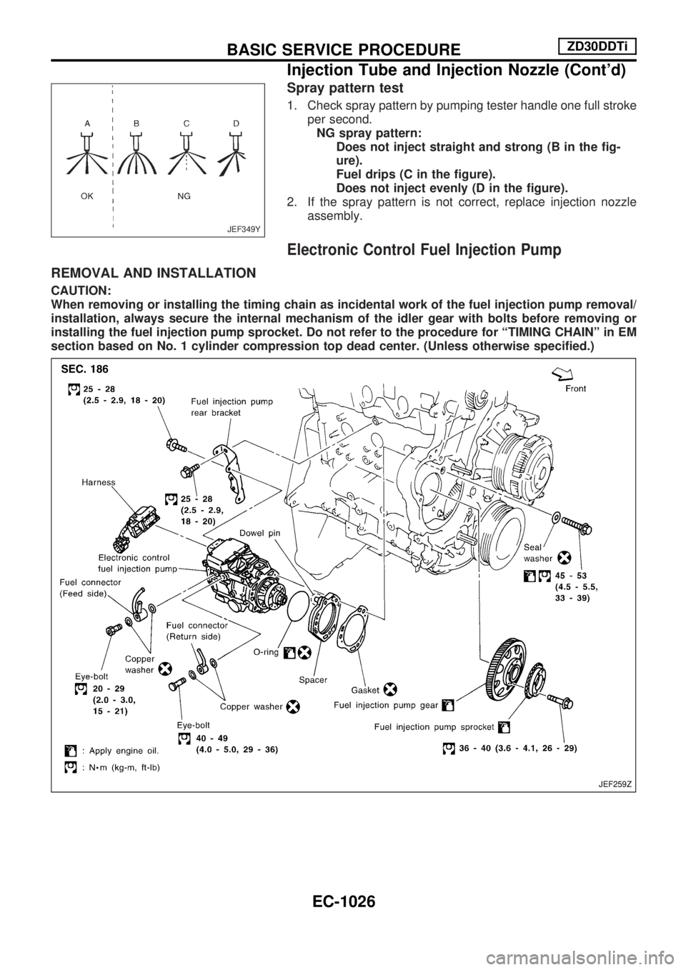
Spray pattern test
1. Check spray pattern by pumping tester handle one full stroke
per second.
NG spray pattern:
Does not inject straight and strong (B in the fig-
ure).
Fuel drips (C in the figure).
Does not inject evenly (D in the figure).
2. If the spray pattern is not correct, replace injection nozzle
assembly.
Electronic Control Fuel Injection Pump
REMOVAL AND INSTALLATION
CAUTION:
When removing or installing the timing chain as incidental work of the fuel injection pump removal/
installation, always secure the internal mechanism of the idler gear with bolts before removing or
installing the fuel injection pump sprocket. Do not refer to the procedure for ªTIMING CHAINº in EM
section based on No. 1 cylinder compression top dead center. (Unless otherwise specified.)
JEF349Y
JEF259Z
BASIC SERVICE PROCEDUREZD30DDTi
Injection Tube and Injection Nozzle (Cont'd)
EC-1026
Page 260 of 1033
REMOVAL
1. Remove the following:
+Engine coolant draining
+Charge air cooler
+Air inlet pipe
+Throttle body
+Rocker cover
+Oil level gauge guide
+EGR guide tube
+EGR volume control solenoid valve
+Fuel hose
+Injection tube
+Radiator upper hose
+Radiator shroud
+Cooling fan
+Drive belt
+Vacuum pipe
+Vacuum pump
2. Move the power steering pump.
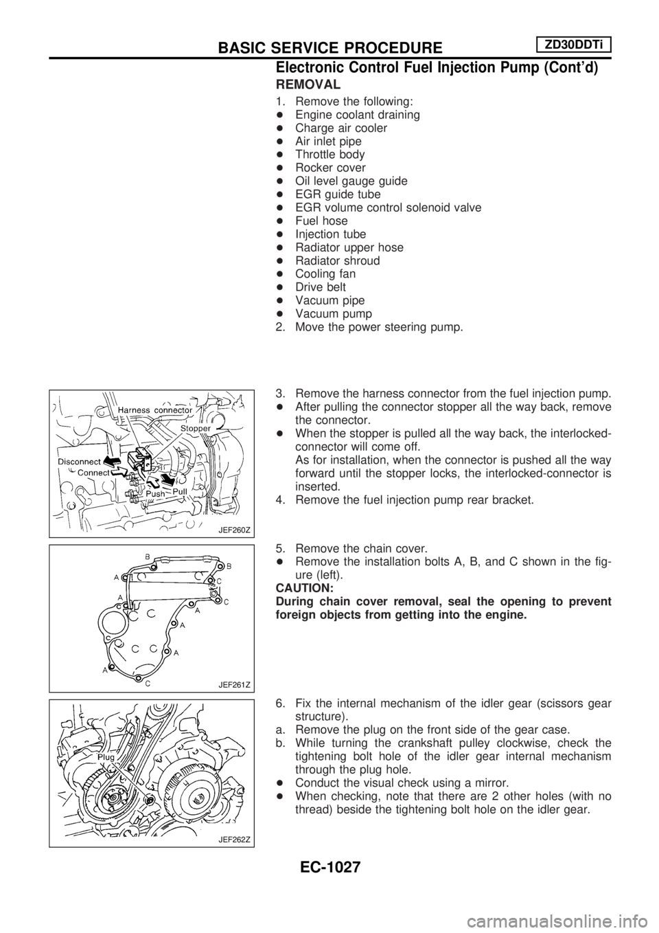
3. Remove the harness connector from the fuel injection pump.
+After pulling the connector stopper all the way back, remove
the connector.
+When the stopper is pulled all the way back, the interlocked-
connector will come off.
As for installation, when the connector is pushed all the way
forward until the stopper locks, the interlocked-connector is
inserted.
4. Remove the fuel injection pump rear bracket.
5. Remove the chain cover.
+Remove the installation bolts A, B, and C shown in the fig-
ure (left).
CAUTION:
During chain cover removal, seal the opening to prevent
foreign objects from getting into the engine.
6. Fix the internal mechanism of the idler gear (scissors gear
structure).
a. Remove the plug on the front side of the gear case.
b. While turning the crankshaft pulley clockwise, check the
tightening bolt hole of the idler gear internal mechanism
through the plug hole.
+Conduct the visual check using a mirror.
+When checking, note that there are 2 other holes (with no
thread) beside the tightening bolt hole on the idler gear.
JEF260Z
JEF261Z
JEF262Z
BASIC SERVICE PROCEDUREZD30DDTi
Electronic Control Fuel Injection Pump (Cont'd)
EC-1027
Page 261 of 1033
![NISSAN PATROL 2000 Electronic Repair Manual c. Install the tightening bolt [Part No.: 81-20620-28, thread
diameter: M6, under head: 20 mm (0.79 in), pitch: 1.0 mm
(0.039 in)] to the idler gear tightening bolt hole, and tighten
to the specified](/manual-img/5/57367/w960_57367-260.png "NISSAN PATROL 2000 Electronic Repair Manual c. Install the tightening bolt [Part No.: 81-20620-28, thread
diameter: M6, under head: 20 mm (0.79 in), pitch: 1.0 mm
(0.039 in)] to the idler gear tightening bolt hole, and tighten
to the specified")
c. Install the tightening bolt [Part No.: 81-20620-28, thread
diameter: M6, under head: 20 mm (0.79 in), pitch: 1.0 mm
(0.039 in)] to the idler gear tightening bolt hole, and tighten
to the specified torque:
: 2.5 - 3.4 Nzm (0.25 - 0.35 kg-m, 22 - 30 in-lb)
CAUTION:
+To protect the idler gear from damage, do not use the
substitute part for the tightening bolt.
+Hereafter, do not turn the crankshaft to avoid hitting
tightening bolt head against the gear case.
+Do not remove the idler gear tightening bolt before
installations of the timing chain and related parts are
completed.
7. Make mating marks on the cam sprocket, fuel injection pump
sprocket, and timing chain with paint.
8. Make mating marks on the fuel injection pump gear and idler
gear with paint.
9. Remove the chain tensioner.
(1) Loosen the upper and lower installation bolts.
(2) While holding the chain tensioner by hand, remove the upper
installation bolt to release the spring tension.
(3) Remove the lower installation bolt first, and then the chain
tensioner.
+Since the chain tensioner does not have a mechanism to
prevent the plunger pop-out, watch out for the fall of the
plunger and spring. (Return prevention mechanism is avail-
able.)
10. Remove the timing chain slack guide.
11. Remove the cam sprocket and timing chain at the same time.
+Make mating marks on each sprocket and timing chain.
+Hold the hexagon head of the camshaft on the exhaust mani-
fold side, and loosen the cam sprocket installation bolt.
CAUTION:
Do not loosen the installation bolt using a chain tension.
12. Remove the fuel injection pump sprocket and gear as an
assembly.
+Fix the fuel injection pump gear with the pulley holder (SST),
and loosen the installation bolt for removal.
+Try not to move the pump shaft when removing.
+Connect the sprocket and gear with a dowel pin, and tighten
them together with the installation bolt.
JEF263Z
JEF264Z
JEF265Z
JEF266Z
JEF267Z
BASIC SERVICE PROCEDUREZD30DDTi
Electronic Control Fuel Injection Pump (Cont'd)
EC-1028
Page 263 of 1033
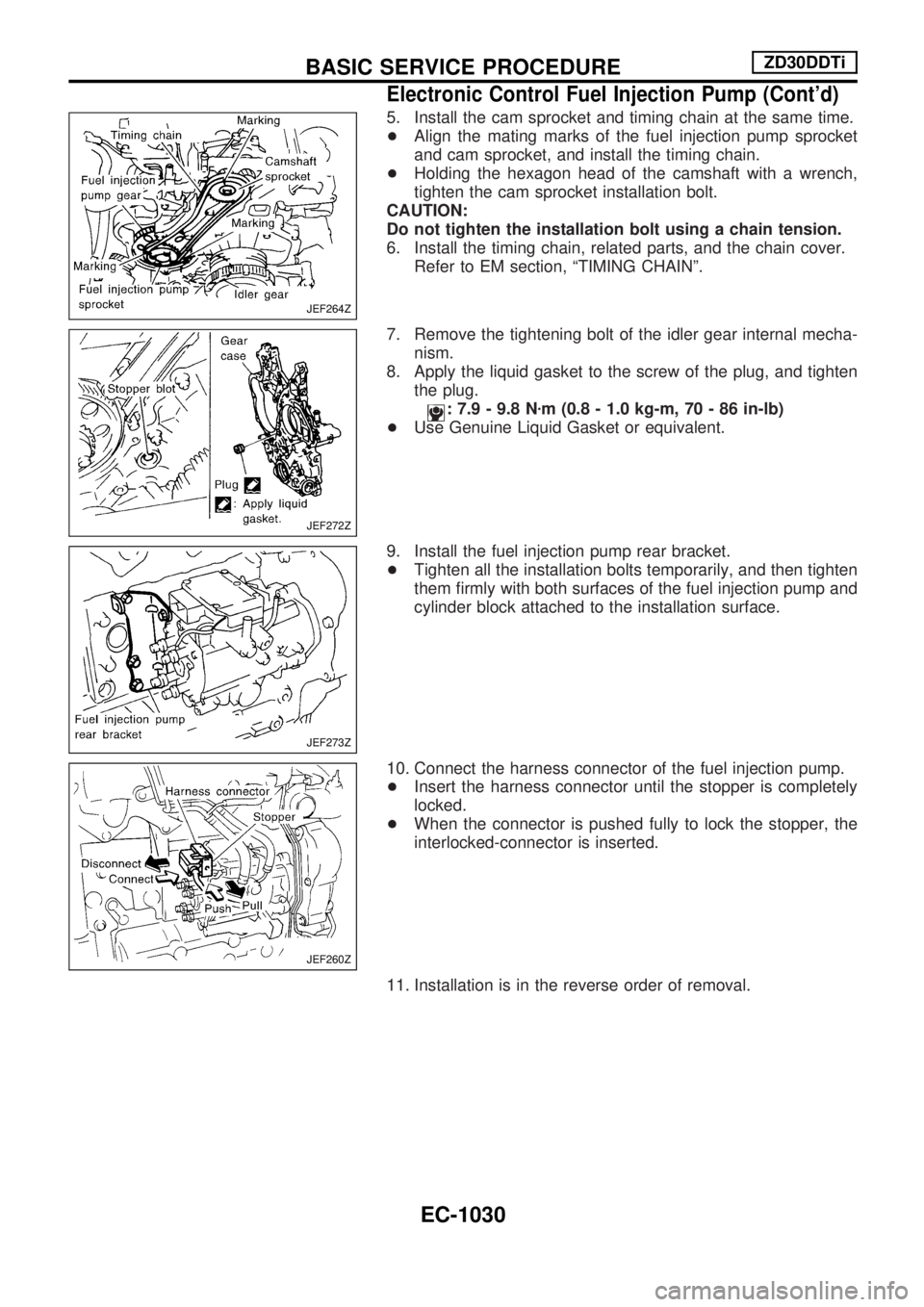
5. Install the cam sprocket and timing chain at the same time.
+Align the mating marks of the fuel injection pump sprocket
and cam sprocket, and install the timing chain.
+Holding the hexagon head of the camshaft with a wrench,
tighten the cam sprocket installation bolt.
CAUTION:
Do not tighten the installation bolt using a chain tension.
6. Install the timing chain, related parts, and the chain cover.
Refer to EM section, ªTIMING CHAINº.
7. Remove the tightening bolt of the idler gear internal mecha-
nism.
8. Apply the liquid gasket to the screw of the plug, and tighten
the plug.
: 7.9 - 9.8 Nzm (0.8 - 1.0 kg-m, 70 - 86 in-lb)
+Use Genuine Liquid Gasket or equivalent.
9. Install the fuel injection pump rear bracket.
+Tighten all the installation bolts temporarily, and then tighten
them firmly with both surfaces of the fuel injection pump and
cylinder block attached to the installation surface.
10. Connect the harness connector of the fuel injection pump.
+Insert the harness connector until the stopper is completely
locked.
+When the connector is pushed fully to lock the stopper, the
interlocked-connector is inserted.
11. Installation is in the reverse order of removal.
JEF264Z
JEF272Z
JEF273Z
JEF260Z
BASIC SERVICE PROCEDUREZD30DDTi
Electronic Control Fuel Injection Pump (Cont'd)
EC-1030
Page 681 of 1033
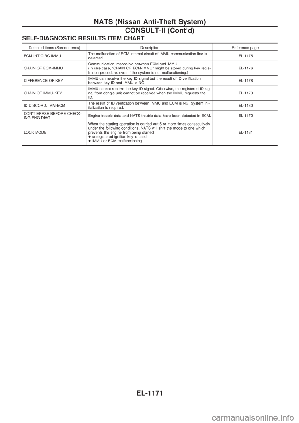
SELF-DIAGNOSTIC RESULTS ITEM CHART
Detected items (Screen terms) Description Reference page
ECM INT CIRC-IMMUThe malfunction of ECM internal circuit of IMMU communication line is
detected.EL-1175
CHAIN OF ECM-IMMUCommunication impossible between ECM and IMMU.
(In rare case, ªCHAIN OF ECM-IMMUº might be stored during key regis-
tration procedure, even if the system is not malfunctioning.)EL-1176
DIFFERENCE OF KEYIMMU can receive the key ID signal but the result of ID verification
between key ID and IMMU is NG.EL-1178
CHAIN OF IMMU-KEYIMMU cannot receive the key ID signal. Otherwise, the registered ID sig-
nal from dongle unit cannot be received when the IMMU requests the
ID.EL-1179
ID DISCORD, IMM-ECMThe result of ID verification between IMMU and ECM is NG. System ini-
tialization is required.EL-1180
DON'T ERASE BEFORE CHECK-
ING ENG DIAGEngine trouble data and NATS trouble data have been detected in ECM. EL-1172
LOCK MODEWhen the starting operation is carried out 5 or more times consecutively
under the following conditions, NATS will shift the mode to one which
prevents the engine from being started.
+unregistered ignition key is used
+IMMU or ECM malfunctioningEL-1181
NATS (Nissan Anti-Theft System)
CONSULT-II (Cont'd)
EL-1171
Page 682 of 1033
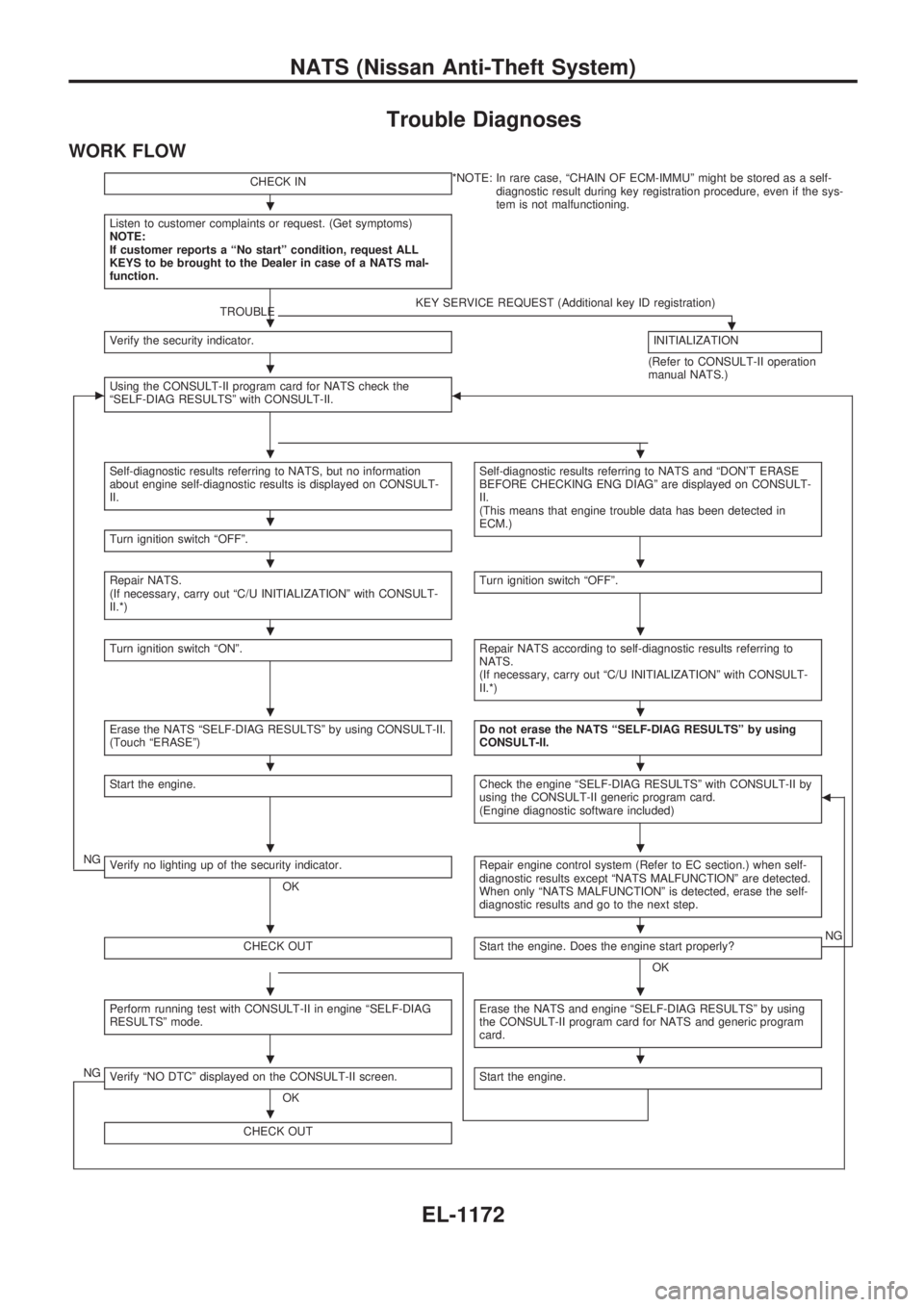
Trouble Diagnoses
WORK FLOW
CHECK IN*NOTE: In rare case, ªCHAIN OF ECM-IMMUº might be stored as a self-
diagnostic result during key registration procedure, even if the sys-
tem is not malfunctioning.
Listen to customer complaints or request. (Get symptoms)
NOTE:
If customer reports a ªNo startº condition, request ALL
KEYS to be brought to the Dealer in case of a NATS mal-
function.
TROUBLEKEY SERVICE REQUEST (Additional key ID registration).Verify the security indicator.INITIALIZATION
(Refer to CONSULT-II operation
manual NATS.)
cUsing the CONSULT-II program card for NATS check the
ªSELF-DIAG RESULTSº with CONSULT-II.b
Self-diagnostic results referring to NATS, but no information
about engine self-diagnostic results is displayed on CONSULT-
II.Self-diagnostic results referring to NATS and ªDON'T ERASE
BEFORE CHECKING ENG DIAGº are displayed on CONSULT-
II.
(This means that engine trouble data has been detected in
ECM.)
Turn ignition switch ªOFFº.
Repair NATS.
(If necessary, carry out ªC/U INITIALIZATIONº with CONSULT-
II.*)Turn ignition switch ªOFFº.
Turn ignition switch ªONº.Repair NATS according to self-diagnostic results referring to
NATS.
(If necessary, carry out ªC/U INITIALIZATIONº with CONSULT-
II.*)
Erase the NATS ªSELF-DIAG RESULTSº by using CONSULT-II.
(Touch ªERASEº)Do not erase the NATS ªSELF-DIAG RESULTSº by using
CONSULT-II.
Start the engine.Check the engine ªSELF-DIAG RESULTSº with CONSULT-II by
using the CONSULT-II generic program card.
(Engine diagnostic software included)b
NGVerify no lighting up of the security indicator.
OKRepair engine control system (Refer to EC section.) when self-
diagnostic results except ªNATS MALFUNCTIONº are detected.
When only ªNATS MALFUNCTIONº is detected, erase the self-
diagnostic results and go to the next step.
CHECK OUTStart the engine. Does the engine start properly?
OKNG
Perform running test with CONSULT-II in engine ªSELF-DIAG
RESULTSº mode.Erase the NATS and engine ªSELF-DIAG RESULTSº by using
the CONSULT-II program card for NATS and generic program
card.
NGVerify ªNO DTCº displayed on the CONSULT-II screen.
OKStart the engine.
CHECK OUT
.
.
.
..
.
..
..
..
..
..
..
..
..
.
NATS (Nissan Anti-Theft System)
EL-1172
Page 683 of 1033
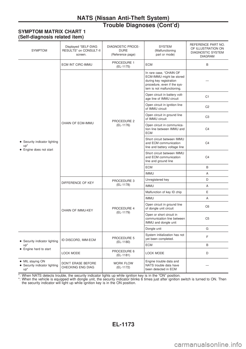
SYMPTOM MATRIX CHART 1
(Self-diagnosis related item)
SYMPTOMDisplayed ªSELF-DIAG
RESULTSº on CONSULT-II
screen.DIAGNOSTIC PROCE-
DURE
(Reference page)SYSTEM
(Malfunctioning
part or mode)REFERENCE PART NO.
OF ILLUSTRATION ON
DIAGNOSTIC SYSTEM
DIAGRAM
+Security indicator lighting
up*
+Engine does not startECM INT CIRC-IMMUPROCEDURE 1
(EL-1175)ECM B
CHAIN OF ECM-IMMUPROCEDURE 2
(EL-1176)In rare case, ªCHAIN OF
ECM-IMMU might be stored
during key registration
procedure, even if the sys-
tem is not malfunctioning.Ð
Open circuit in battery volt-
age line of IMMU circuitC1
Open circuit in ignition line
of IMMU circuitC2
Open circuit in ground line
of IMMU circuitC3
Open circuit in communica-
tion line between IMMU and
ECMC4
Short circuit between IMMU
and ECM communication
line and battery voltage lineC4
Short circuit between IMMU
and ECM communication
line and ground lineC4
ECM B
IMMU A
DIFFERENCE OF KEYPROCEDURE 3
(EL-1178)Unregistered key D
IMMU A
CHAIN OF IMMU-KEYPROCEDURE 4
(EL-1179)Malfunction of key ID chip E
IMMU A
Open circuit in ground line
of dongle unit circuitC6
Open or short circuit in
communication line between
IMMU and dongle unitC5
Dongle unit G
+Security indicator lighting
up*
+Engine hard to startID DISCORD, IMM-ECMPROCEDURE 5
(EL-1180)System initialization has not
yet been completed.F
ECM B
LOCK MODEPROCEDURE 6
(EL-1181)LOCK MODE D
+MIL staying ON
+Security indicator lighting
up*DON'T ERASE BEFORE
CHECKING ENG DIAGWORK FLOW
(EL-1172)Engine trouble data and
NATS trouble data have
been detected in ECMÐ
*: When NATS detects trouble, the security indicator lights up while ignition key is in the ªONº position.
*: When the vehicle is equipped with dongle unit, the security indicator blinks 6 times just after ignition switch is turned to ON. Then
the security indicator will light up while ignition key is in the ON position.
NATS (Nissan Anti-Theft System)
Trouble Diagnoses (Cont'd)
EL-1173
Page 686 of 1033
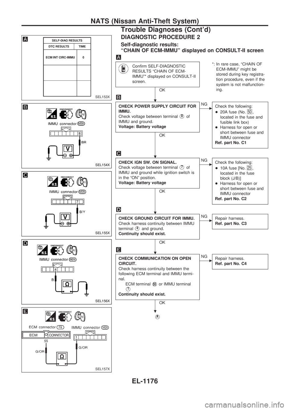
DIAGNOSTIC PROCEDURE 2
Self-diagnostic results:
ªCHAIN OF ECM-IMMUº displayed on CONSULT-II screen
Confirm SELF-DIAGNOSTIC
RESULTS ªCHAIN OF ECM-
IMMUº* displayed on CONSULT-II
screen.
OK*: In rare case, ªCHAIN OF
ECM-IMMUº might be
stored during key registra-
tion procedure, even if the
system is not malfunction-
ing.
CHECK POWER SUPPLY CIRCUIT FOR
IMMU.
Check voltage between terminal
V8of
IMMU and ground.
Voltage: Battery voltage
OK
cNG
Check the following:
+20A fuse (No.
50,
located in the fuse and
fusible link box)
+Harness for open or
short between fuse and
IMMU connector
Ref. part No. C1
CHECK IGN SW. ON SIGNAL.
Check voltage between terminal
V7of
IMMU and ground while ignition switch is
in the ªONº position.
Voltage: Battery voltage
OK
cNG
Check the following:
+10A fuse [No.
25,
located in the fuse
block (J/B)]
+Harness for open or
short between fuse and
IMMU connector
Ref. part No. C2
CHECK GROUND CIRCUIT FOR IMMU.
Check harness continuity between IMMU
terminal
V4and ground.
Continuity should exist.
OK
cNG
Repair harness.
Ref. part No. C3
CHECK COMMUNICATION ON OPEN
CIRCUIT.
Check harness continuity between the
following ECM terminal and IMMU termi-
nal.
ECM terminal
V55or IMMU terminal
V1
Continuity should exist.
OK
cNG
Repair harness.
Ref. part No. C4
VA
SEL153X
SEL154X
SEL155X
SEL156X
SEL157X
.
.
.
.
.
NATS (Nissan Anti-Theft System)
Trouble Diagnoses (Cont'd)
EL-1176