Page 768 of 1033
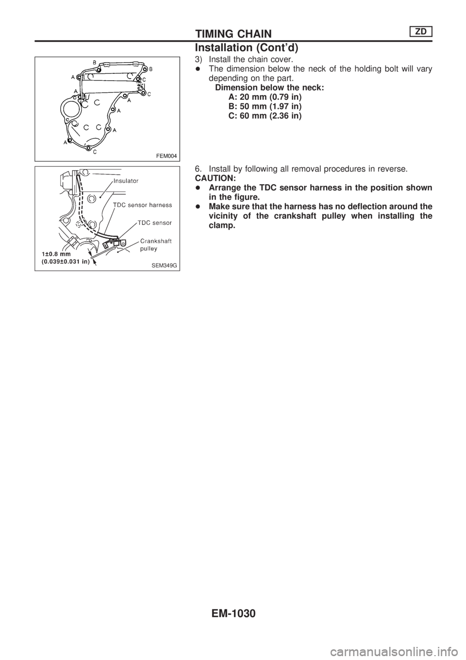
3) Install the chain cover.
+The dimension below the neck of the holding bolt will vary
depending on the part.
Dimension below the neck:
A: 20 mm (0.79 in)
B: 50 mm (1.97 in)
C: 60 mm (2.36 in)
6. Install by following all removal procedures in reverse.
CAUTION:
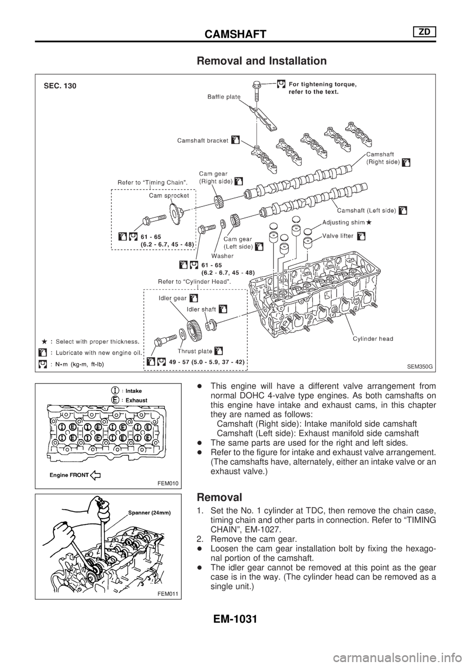
+Arrange the TDC sensor harness in the position shown
in the figure.
+Make sure that the harness has no deflection around the
vicinity of the crankshaft pulley when installing the
clamp.
FEM004
SEM349G
TIMING CHAINZD
Installation (Cont'd)
EM-1030
Page 769 of 1033
Removal and Installation
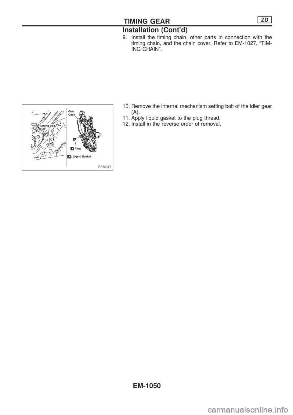
+This engine will have a different valve arrangement from
normal DOHC 4-valve type engines. As both camshafts on
this engine have intake and exhaust cams, in this chapter
they are named as follows:
Camshaft (Right side): Intake manifold side camshaft
Camshaft (Left side): Exhaust manifold side camshaft
+The same parts are used for the right and left sides.
+Refer to the figure for intake and exhaust valve arrangement.
(The camshafts have, alternately, either an intake valve or an
exhaust valve.)
Removal
1. Set the No. 1 cylinder at TDC, then remove the chain case,
timing chain and other parts in connection. Refer to ªTIMING
CHAINº, EM-1027.
2. Remove the cam gear.
+Loosen the cam gear installation bolt by fixing the hexago-
nal portion of the camshaft.
+The idler gear cannot be removed at this point as the gear
case is in the way. (The cylinder head can be removed as a
single unit.)
SEM350G
FEM010
FEM011
CAMSHAFTZD
EM-1031
Page 773 of 1033
5. Install the cam gear.
+Align the match marks, and install the idler gear and each
cam gear to the position shown in the figure.
+Tighten the cam gear installation bolt by fixing the hexago-
nal portion of the camshaft.
6. Install the timing chain, all other related parts and chain
cover.
Refer to ªTIMING CHAINº, EM-1027.
7. After installing the timing chain, check and adjust the valve
clearance before installing the spill tube.
Refer to ªVALVE CLEARANCEº, EM-1036.
8. Install in the reverse order of removal.
FEM023
CAMSHAFTZD
Installation (Cont'd)
EM-1035
Page 778 of 1033
Removal
1. Remove the following parts.
+Undercover
+Engine oil (Drain)
+Engine coolant (Drain)
+Engine cover
+Intercooler
+Air inlet pipe
+Air cleaner case
+Throttle body
+Swirl and intake air control valve control solenoid valve and
bracket
+Vacuum tank
+Glow plate
+Rocker cover
+Spill tube
+Radiator shrouds (Rear and Lower)
+Cooling fan
+Radiator hose (Upper and Lower)
+Auxiliary belt and auto tensioner.
2. Remove the alternator.
3. Remove the A/C compressor and bracket with piping con-
nected. Move and support it at the LH side of engine bay with
a rope to avoid putting load on piping.
Refer to HA section in Nissan Service Manual (Supplement
I: Publication No. SM0E-Y61AE0E.)
4. Remove the chain cover, timing chain and other parts in
connection.
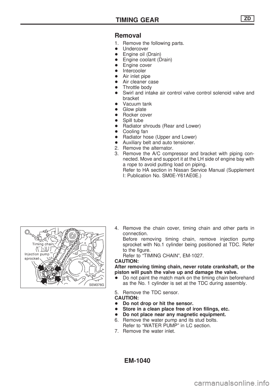
Before removing timing chain, remove injection pump
sprocket with No.1 cylinder being positioned at TDC. Refer
to the figure.
Refer to ªTIMING CHAINº, EM-1027.
CAUTION:
After removing timing chain, never rotate crankshaft, or the
piston will push the valve up and damage the valve.
+Do not paint the match mark on the timing chain beforehand
as the No. 1 cylinder is set at the TDC during assembly.
5. Remove the TDC sensor.
CAUTION:
+Do not drop or hit the sensor.
+Store in a clean place free of iron filings, etc.
+Do not place near any magnetic equipment.
6. Remove the water pump and its stud bolts.
Refer to ªWATER PUMPº in LC section.
7. Remove the water inlet.
SEM376G
TIMING GEARZD
EM-1040
Page 779 of 1033
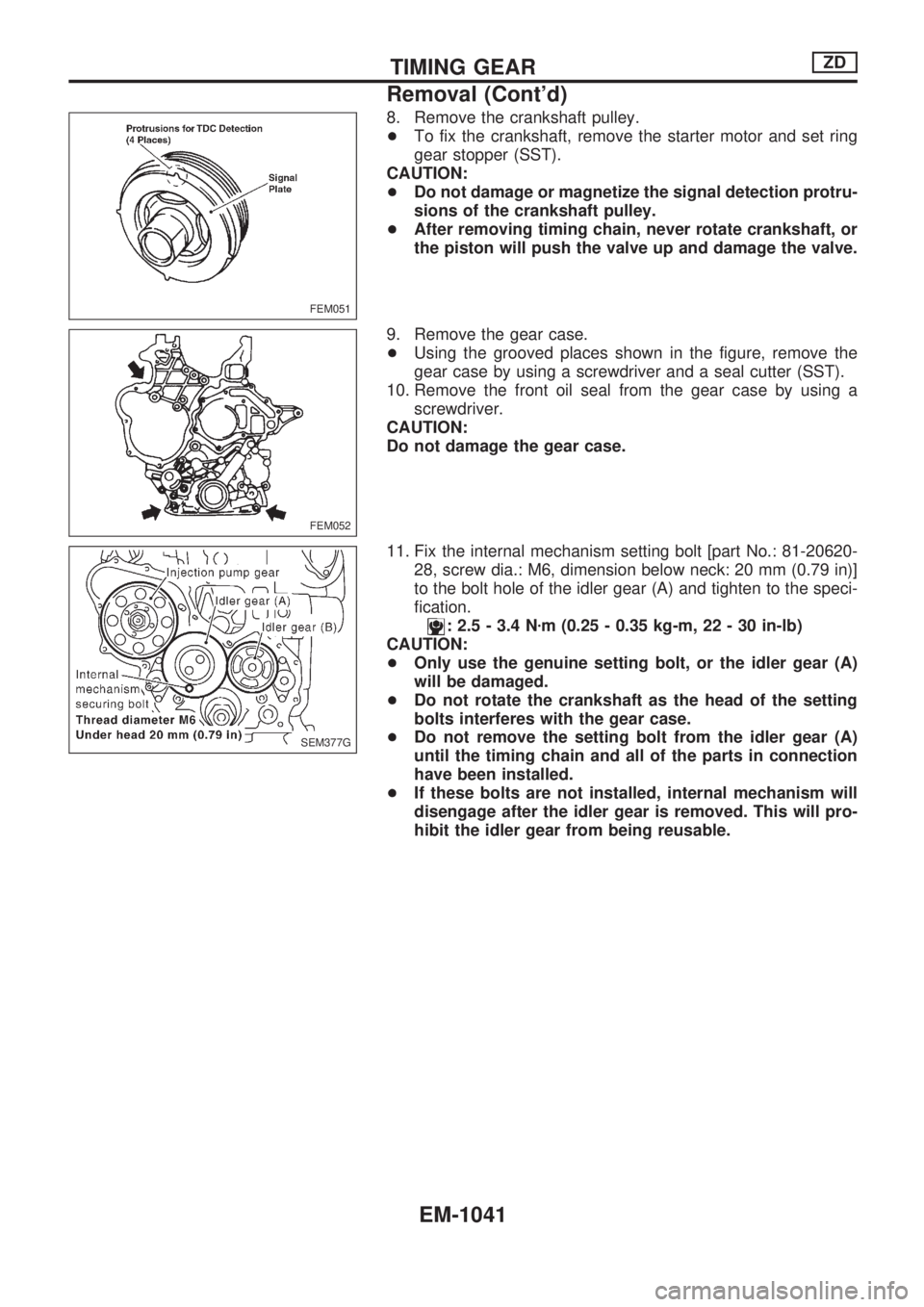
8. Remove the crankshaft pulley.
+To fix the crankshaft, remove the starter motor and set ring
gear stopper (SST).
CAUTION:
+Do not damage or magnetize the signal detection protru-
sions of the crankshaft pulley.
+After removing timing chain, never rotate crankshaft, or
the piston will push the valve up and damage the valve.
9. Remove the gear case.
+Using the grooved places shown in the figure, remove the
gear case by using a screwdriver and a seal cutter (SST).
10. Remove the front oil seal from the gear case by using a
screwdriver.
CAUTION:
Do not damage the gear case.
11. Fix the internal mechanism setting bolt [part No.: 81-20620-
28, screw dia.: M6, dimension below neck: 20 mm (0.79 in)]
to the bolt hole of the idler gear (A) and tighten to the speci-
fication.
: 2.5 - 3.4 Nzm (0.25 - 0.35 kg-m, 22 - 30 in-lb)
CAUTION:
+Only use the genuine setting bolt, or the idler gear (A)
will be damaged.
+Do not rotate the crankshaft as the head of the setting
bolts interferes with the gear case.
+Do not remove the setting bolt from the idler gear (A)
until the timing chain and all of the parts in connection
have been installed.
+If these bolts are not installed, internal mechanism will
disengage after the idler gear is removed. This will pro-
hibit the idler gear from being reusable.
FEM051
FEM052
SEM377G
TIMING GEARZD
Removal (Cont'd)
EM-1041
Page 788 of 1033
9. Install the timing chain, other parts in connection with the
timing chain, and the chain cover. Refer to EM-1027, ªTIM-
ING CHAINº.
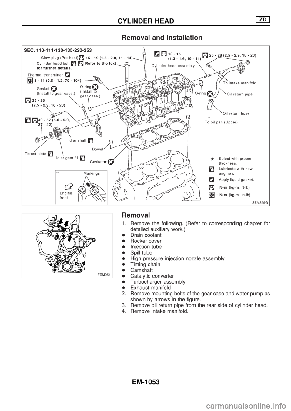
10. Remove the internal mechanism setting bolt of the idler gear
(A).
11. Apply liquid gasket to the plug thread.
12. Install in the reverse order of removal.
FEM047
TIMING GEARZD
Installation (Cont'd)
EM-1050
Page 789 of 1033
VALVE OIL SEAL
1. Remove timing chain. Refer to EM-1027, ªTIMING CHAINº.
2. Remove injection nozzle assembly. Refer to ªInjection Tube
and Injection Nozzleº in ªBASIC SERVICE PROCEDUREº in
EC section.
3. Remove camshaft. Refer to EM-1031, ªCAMSHAFTº.
4. Remove valve lifters and mark order No. on each lifter.
5. Replace valve oil seal according to the following procedure.
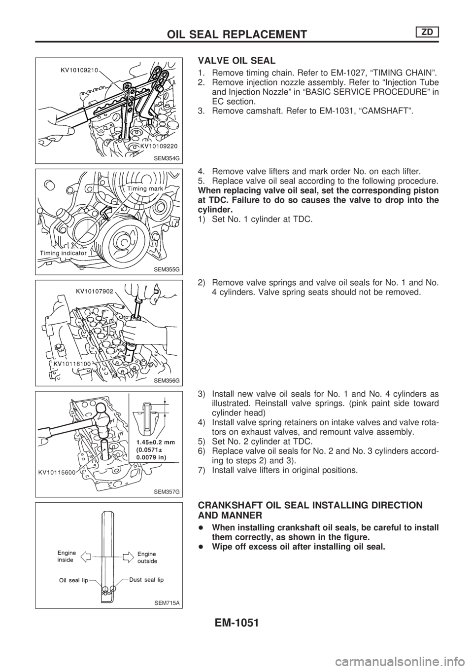
When replacing valve oil seal, set the corresponding piston
at TDC. Failure to do so causes the valve to drop into the
cylinder.
1) Set No. 1 cylinder at TDC.
2) Remove valve springs and valve oil seals for No. 1 and No.
4 cylinders. Valve spring seats should not be removed.
3) Install new valve oil seals for No. 1 and No. 4 cylinders as
illustrated. Reinstall valve springs. (pink paint side toward
cylinder head)
4) Install valve spring retainers on intake valves and valve rota-
tors on exhaust valves, and remount valve assembly.
5) Set No. 2 cylinder at TDC.
6) Replace valve oil seals for No. 2 and No. 3 cylinders accord-
ing to steps 2) and 3).
7) Install valve lifters in original positions.
CRANKSHAFT OIL SEAL INSTALLING DIRECTION
AND MANNER
+When installing crankshaft oil seals, be careful to install
them correctly, as shown in the figure.
+Wipe off excess oil after installing oil seal.
SEM354G
SEM355G
SEM356G
SEM357G
SEM715A
OIL SEAL REPLACEMENTZD
EM-1051
Page 791 of 1033
Removal and Installation
Removal
1. Remove the following. (Refer to corresponding chapter for
detailed auxiliary work.)
+Drain coolant
+Rocker cover
+Injection tube
+Spill tube
+High pressure injection nozzle assembly
+Timing chain
+Camshaft
+Catalytic converter
+Turbocharger assembly
+Exhaust manifold
2. Remove mounting bolts of the gear case and water pump as
shown by arrows in the figure.
3. Remove oil return pipe from the rear side of cylinder head.
4. Remove intake manifold.
SEM359G
FEM054
CYLINDER HEADZD
EM-1053