Page 82 of 1033
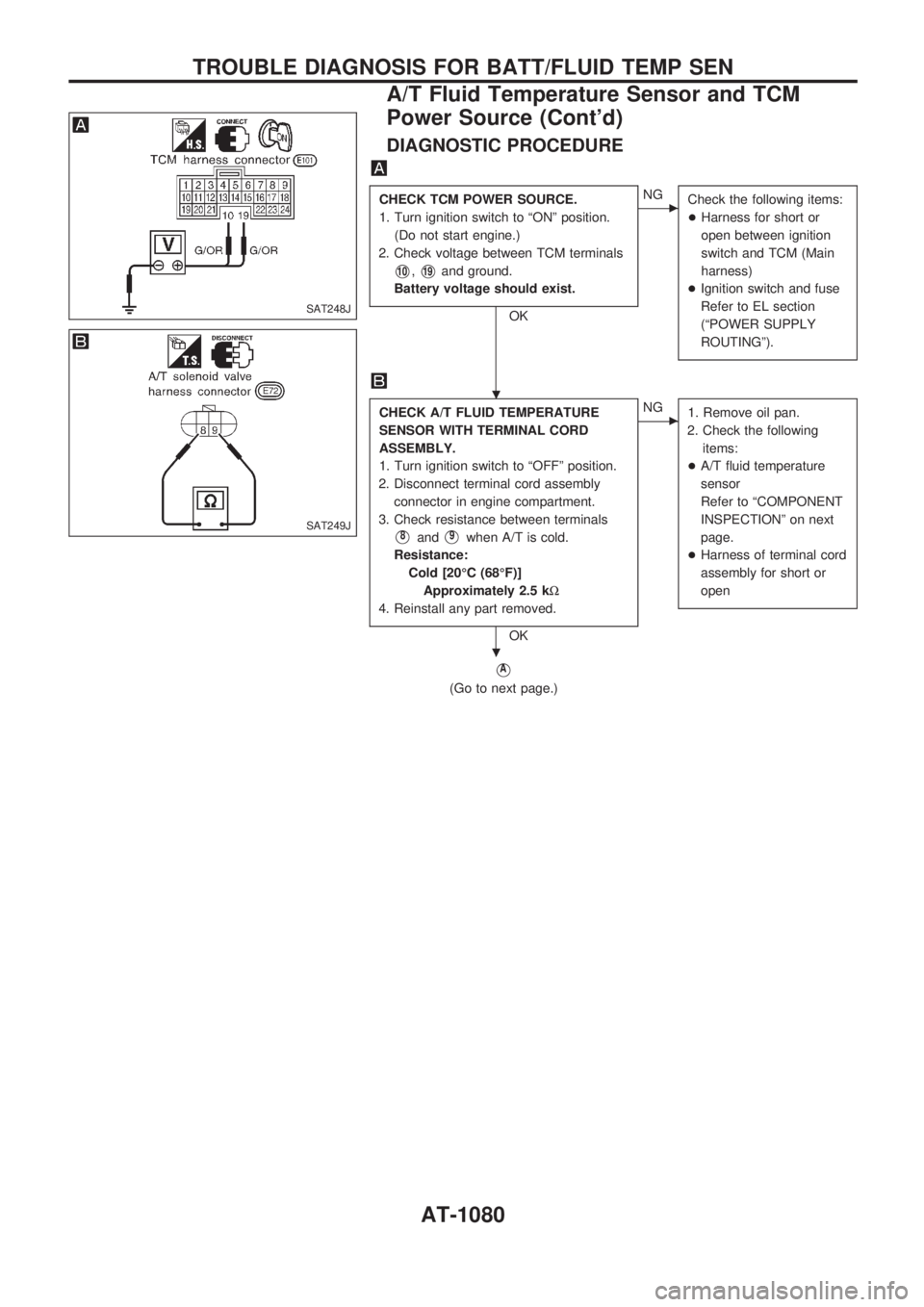
DIAGNOSTIC PROCEDURE
CHECK TCM POWER SOURCE.
1. Turn ignition switch to ªONº position.
(Do not start engine.)
2. Check voltage between TCM terminals
V10,V19and ground.
Battery voltage should exist.
OK
cNG
Check the following items:
+Harness for short or
open between ignition
switch and TCM (Main
harness)
+Ignition switch and fuse
Refer to EL section
(ªPOWER SUPPLY
ROUTINGº).
CHECK A/T FLUID TEMPERATURE
SENSOR WITH TERMINAL CORD
ASSEMBLY.
1. Turn ignition switch to ªOFFº position.
2. Disconnect terminal cord assembly
connector in engine compartment.
3. Check resistance between terminals
V8andV9when A/T is cold.
Resistance:
Cold [20ÉC (68ÉF)]
Approximately 2.5 kW
4. Reinstall any part removed.
OK
cNG
1. Remove oil pan.
2. Check the following
items:
+A/T fluid temperature
sensor
Refer to ªCOMPONENT
INSPECTIONº on next
page.
+Harness of terminal cord
assembly for short or
open
VA
(Go to next page.)
SAT248J
SAT249J
.
.
TROUBLE DIAGNOSIS FOR BATT/FLUID TEMP SEN
A/T Fluid Temperature Sensor and TCM
Power Source (Cont'd)
AT-1080
Page 99 of 1033
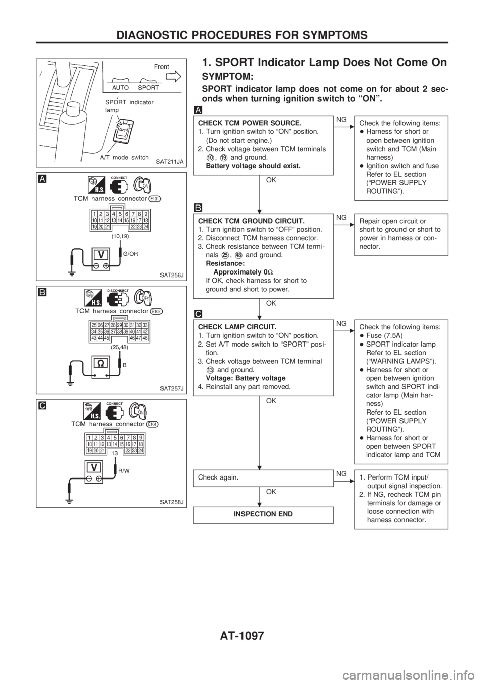
1. SPORT Indicator Lamp Does Not Come On
SYMPTOM:
SPORT indicator lamp does not come on for about 2 sec-
onds when turning ignition switch to ªONº.
CHECK TCM POWER SOURCE.
1. Turn ignition switch to ªONº position.
(Do not start engine.)
2. Check voltage between TCM terminals
V10,V19and ground.
Battery voltage should exist.
OK
cNG
Check the following items:
+Harness for short or
open between ignition
switch and TCM (Main
harness)
+Ignition switch and fuse
Refer to EL section
(ªPOWER SUPPLY
ROUTINGº).
CHECK TCM GROUND CIRCUIT.
1. Turn ignition switch to ªOFFº position.
2. Disconnect TCM harness connector.
3. Check resistance between TCM termi-
nals
V25,V48and ground.
Resistance:
Approximately 0W
If OK, check harness for short to
ground and short to power.
OK
cNG
Repair open circuit or
short to ground or short to
power in harness or con-
nector.
CHECK LAMP CIRCUIT.
1. Turn ignition switch to ªONº position.
2. Set A/T mode switch to ªSPORTº posi-
tion.
3. Check voltage between TCM terminal
V13and ground.
Voltage: Battery voltage
4. Reinstall any part removed.
OK
cNG
Check the following items:
+Fuse (7.5A)
+SPORT indicator lamp
Refer to EL section
(ªWARNING LAMPSº).
+Harness for short or
open between ignition
switch and SPORT indi-
cator lamp (Main har-
ness)
Refer to EL section
(ªPOWER SUPPLY
ROUTINGº).
+Harness for short or
open between SPORT
indicator lamp and TCM
Check again.
OK
cNG
1. Perform TCM input/
output signal inspection.
2. If NG, recheck TCM pin
terminals for damage or
loose connection with
harness connector.
INSPECTION END
SAT211JA
SAT256J
SAT257J
SAT258J
.
.
. .
.
DIAGNOSTIC PROCEDURES FOR SYMPTOMS
AT-1097
Page 120 of 1033
Diagnostic Procedure
SYMPTOM 1:
+Selector lever cannot be moved from ªPº position with
key in ªONº position and brake pedal applied.
+Selector lever can be moved from ªPº position with key
in ªONº position and brake pedal released.
+Selector lever can be moved from ªPº position when key
is removed from key cylinder.
SYMPTOM 2:
Ignition key cannot be removed when selector lever is set to
ªPº position. It can be removed when selector lever is set to
any position except ªPº.
Check key interlock cable for damage.
OK
cNG
Repair key interlock cable.
Refer to ªKey Interlock
Cableº, AT-1121.
Check selector lever position for damage.
OK
cNG
Check selector lever.
Refer to ªON-VEHICLE
SERVICE Ð PNP Switch
and Manual Control Link-
age Adjustmentº.
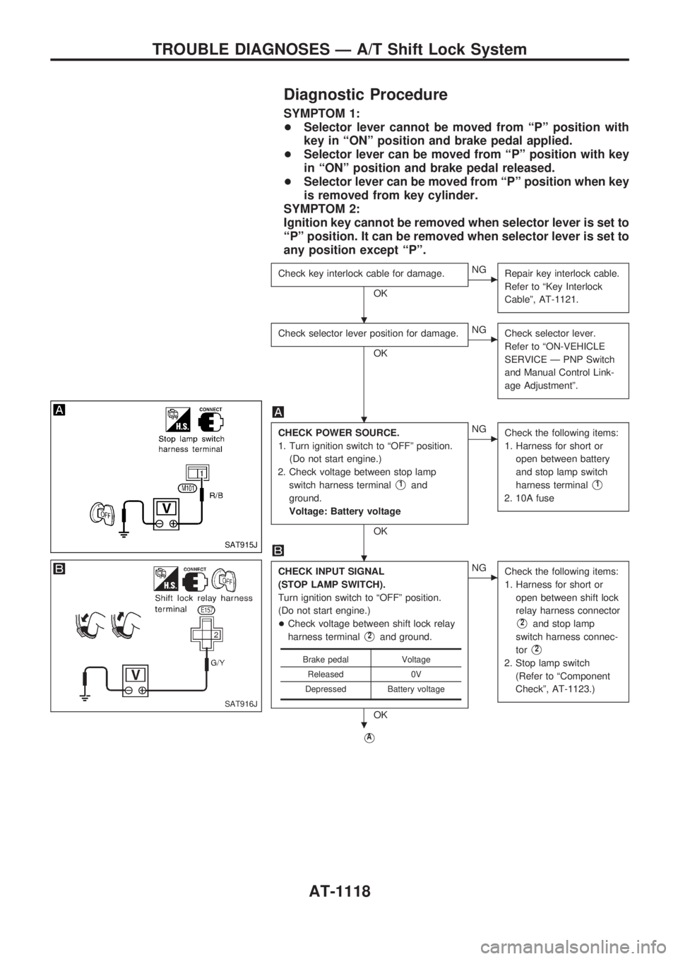
CHECK POWER SOURCE.
1. Turn ignition switch to ªOFFº position.
(Do not start engine.)
2. Check voltage between stop lamp
switch harness terminal
V1and
ground.
Voltage: Battery voltage
OK
cNG
Check the following items:
1. Harness for short or
open between battery
and stop lamp switch
harness terminal
V1
2. 10A fuse
CHECK INPUT SIGNAL
(STOP LAMP SWITCH).
Turn ignition switch to ªOFFº position.
(Do not start engine.)
+Check voltage between shift lock relay
harness terminal
V2and ground.
OK
cNG
Check the following items:
1. Harness for short or
open between shift lock
relay harness connector
V2and stop lamp
switch harness connec-
tor
V2
2. Stop lamp switch
(Refer to ªComponent
Checkº, AT-1123.)
VA
Brake pedal Voltage
Released 0V
Depressed Battery voltage
SAT915J
SAT916J
.
.
.
.
TROUBLE DIAGNOSES Ð A/T Shift Lock System
AT-1118
Page 121 of 1033
VA
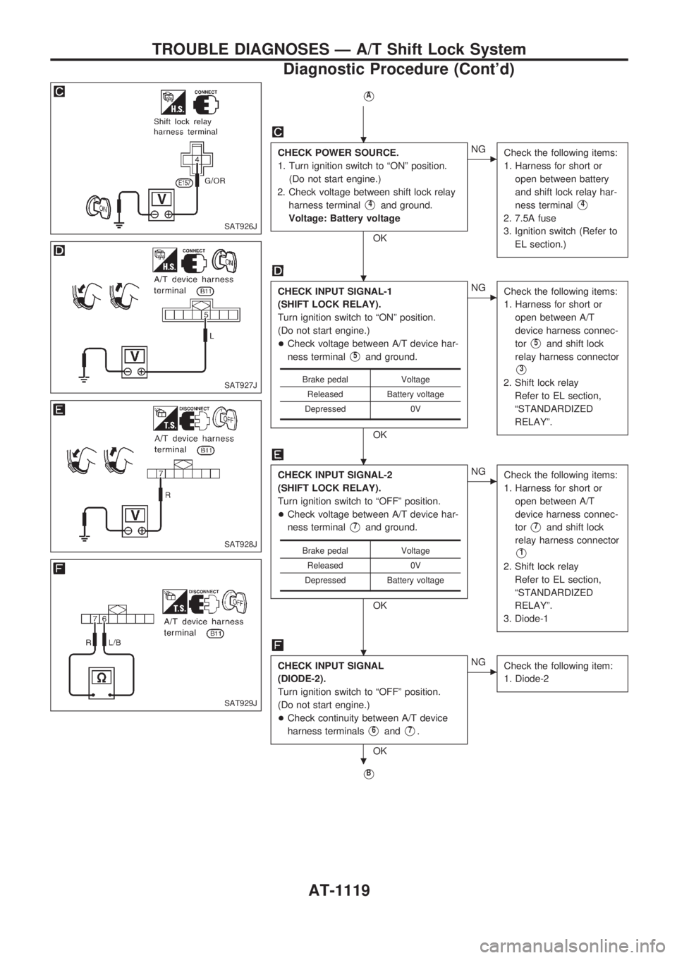
CHECK POWER SOURCE.
1. Turn ignition switch to ªONº position.
(Do not start engine.)
2. Check voltage between shift lock relay
harness terminal
V4and ground.
Voltage: Battery voltage
OK
cNG
Check the following items:
1. Harness for short or
open between battery
and shift lock relay har-
ness terminal
V4
2. 7.5A fuse
3. Ignition switch (Refer to
EL section.)
CHECK INPUT SIGNAL-1
(SHIFT LOCK RELAY).
Turn ignition switch to ªONº position.
(Do not start engine.)
+Check voltage between A/T device har-
ness terminal
V5and ground.
OK
cNG
Check the following items:
1. Harness for short or
open between A/T
device harness connec-
tor
V5and shift lock
relay harness connector
V3
2. Shift lock relay
Refer to EL section,
ªSTANDARDIZED
RELAYº.
CHECK INPUT SIGNAL-2
(SHIFT LOCK RELAY).
Turn ignition switch to ªOFFº position.
+Check voltage between A/T device har-
ness terminal
V7and ground.
OK
cNG
Check the following items:
1. Harness for short or
open between A/T
device harness connec-
tor
V7and shift lock
relay harness connector
V1
2. Shift lock relay
Refer to EL section,
ªSTANDARDIZED
RELAYº.
3. Diode-1
CHECK INPUT SIGNAL
(DIODE-2).
Turn ignition switch to ªOFFº position.
(Do not start engine.)
+Check continuity between A/T device
harness terminals
V6andV7.
OK
cNG
Check the following item:
1. Diode-2
VB
Brake pedal Voltage
Released Battery voltage
Depressed 0V
Brake pedal Voltage
Released 0V
Depressed Battery voltage
SAT926J
SAT927J
SAT928J
SAT929J
.
.
.
.
.
TROUBLE DIAGNOSES Ð A/T Shift Lock System
Diagnostic Procedure (Cont'd)
AT-1119
Page 313 of 1033
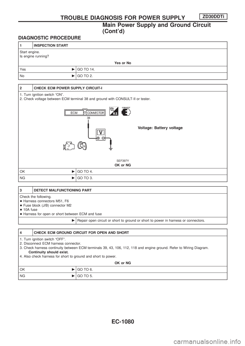
DIAGNOSTIC PROCEDURE
1 INSPECTION START
Start engine.
Is engine running?
Yes or No
YescGO TO 14.
NocGO TO 2.
2 CHECK ECM POWER SUPPLY CIRCUIT-I
1. Turn ignition switch ªONº.
2. Check voltage between ECM terminal 38 and ground with CONSULT-II or tester.
SEF397Y
OK or NG
OKcGO TO 4.
NGcGO TO 3.
3 DETECT MALFUNCTIONING PART
Check the following.
+Harness connectors M51, F6
+Fuse block (J/B) connector M2
+10A fuse
+Harness for open or short between ECM and fuse
cRepair open circuit or short to ground or short to power in harness or connectors.
4 CHECK ECM GROUND CIRCUIT FOR OPEN AND SHORT
1. Turn ignition switch ªOFFº.
2. Disconnect ECM harness connector.
3. Check harness continuity between ECM terminals 39, 43, 106, 112, 118 and engine ground. Refer to Wiring Diagram.
Continuity should exist.
4. Also check harness for short to ground and short to power.
OK or NG
OKcGO TO 6.
NGcGO TO 5.
TROUBLE DIAGNOSIS FOR POWER SUPPLYZD30DDTi
Main Power Supply and Ground Circuit
(Cont'd)
EC-1080
Page 315 of 1033
7 CHECK ECM POWER SUPPLY CIRCUIT-III
1. Disconnect ECM relay.
SEF225Z
2. Check voltage between relay terminals 1, 3 and ground with CONSULT-II or tester.
SEF289Z
OK or NG
OKcGO TO 9.
NGcGO TO 8.
8 DETECT MALFUNCTIONING PART
Check the following.
+Harness connectors E104, M86 or E127, M21
+20A fuse
+Harness for open or short between ECM relay and battery
cRepair open circuit or short to ground or short to power in harness or connectors.
9 CHECK OUTPUT SIGNAL CIRCUIT FOR OPEN AND SHORT
1. Disconnect ECM harness connector.
2. Check harness continuity between ECM terminal 4 and ECM relay terminal 2. Refer to Wiring Diagram.
Continuity should exist.
3. Also check harness for short to ground and short to power.
OK or NG
OKcGO TO 11.
NGcGO TO 10.
TROUBLE DIAGNOSIS FOR POWER SUPPLYZD30DDTi
Main Power Supply and Ground Circuit
(Cont'd)
EC-1082
Page 317 of 1033
14 CHECK ECM POWER SUPPLY CIRCUIT-V
1. Reconnect all harness connectors disconnected.
2. Turn ignition switch ªONº.
3. Check voltage between ECM terminal 102 and ground with CONSULT-II or tester.
SEF290Z
OK or NG
OKcGO TO 16.
NGcGO TO 15.
15 DETECT MALFUNCTIONING PART
Check the following.
+Harness connectors M52, F7
+Fuse block (J/B) connector M2
+10A fuse
+Harness for open or short between ECM and fuse
cRepair open circuit or short to ground or short to power in harness or connectors.
16 CHECK ECM POWER SUPPLY CIRCUIT-VI
1. Turn ignition switch ªOFFº.
2. Disconnect ECM relay.
SEF225Z
3. Disconnect ECM harness connector.
4. Check harness continuity between ECM terminals 56, 61, 116 and ECM relay terminal 5. Refer to Wiring Diagram.
Continuity should exist.
5. Also check harness for short to ground and short to power.
OK or NG
OKcGO TO 18.
NGcGO TO 17.
TROUBLE DIAGNOSIS FOR POWER SUPPLYZD30DDTi
Main Power Supply and Ground Circuit
(Cont'd)
EC-1084
Page 344 of 1033
4 CHECK COOLING FAN POWER SUPPLY CIRCUIT
1. Turn ignition switch ªOFFº.
2. Disconnect cooling fan relay-1.
SEF690V
3. Turn ignition switch ªONº.
4. Check voltage between cooling fan relay-1 terminals 2, 5 and ground with CONSULT-II or tester.
SEF291Z
OK or NG
OKcGO TO 6.
NGcGO TO 5.
5 DETECT MALFUNCTIONING PART
Check the following.
+Fuse block (J/B) connector E112
+10A fuse or 20A fuse
+30A fusible links
+Harness for open or short between cooling fan relay-1 and fuse
+Harness for open or short between cooling fan relay-1 and battery
cRepair open circuit or short to ground or short to power in harness or connectors.
DTC 0208 OVER HEATZD30DDTi
Diagnostic Procedure (Cont'd)
EC-1111