2000 NISSAN PATROL Engine revolution sensor
[x] Cancel search: Engine revolution sensorPage 3 of 1033

AUTOMATIC TRANSMISSION
SECTION
AT
CONTENTS
PREPARATION AND PRECAUTIONS............... 1003
Special Service Tools ...................................... 1003
Supplemental Restraint System (SRS) ªAIR
BAGº and ªSEAT BELT PRE-TENSIONERº ... 1004
Precautions ...................................................... 1004
Service Notice or Precautions ......................... 1006
OVERALL SYSTEM............................................ 1007
A/T Electrical Parts Location ........................... 1007
Circuit Diagram ................................................ 1008
Wiring Diagram Ð A/T Ð ................................ 1009
Cross-sectional View ....................................... 1022
Hydraulic Control Circuits ................................ 1023
Shift Mechanism .............................................. 1024
Control System ................................................ 1026
ON BOARD DIAGNOSTIC SYSTEM
DESCRIPTION..................................................... 1028
Self-diagnosis................................................... 1028
Diagnosis by CONSULT-II ............................... 1034
TROUBLE DIAGNOSIS Ð Introduction............ 1036
Introduction ...................................................... 1036
Diagnostic Worksheet ...................................... 1037
Work Flow ........................................................ 1040
TROUBLE DIAGNOSIS Ð Basic Inspection.... 1041
A/T Fluid Check ............................................... 1041
Stall Test .......................................................... 1041
Line Pressure Test........................................... 1044
Road Test ........................................................ 1046
TROUBLE DIAGNOSIS Ð General
Description.......................................................... 1057
Symptom Chart ................................................ 1057
TCM Terminals and Reference Value ............. 1060
TROUBLE DIAGNOSIS FOR VHCL SPEED
SENzA/T................................................................ 1064Vehicle Speed SensorzA/T (Revolution
sensor) ............................................................. 1064
TROUBLE DIAGNOSIS FOR VHCL SPEED
SENzMTR.............................................................. 1066
Vehicle Speed SensorzzMTR ............................ 1066
TROUBLE DIAGNOSIS FOR THROTTLE POSI
SEN...................................................................... 1068
Accelerator Position Sensor ............................ 1068
TROUBLE DIAGNOSIS FOR SHIFT
SOLENOID/V A.................................................... 1070
Shift Solenoid Valve A ..................................... 1070
TROUBLE DIAGNOSIS FOR SHIFT
SOLENOID/V B.................................................... 1072
Shift Solenoid Valve B ..................................... 1072
TROUBLE DIAGNOSIS FOR OVERRUN
CLUTCH S/V........................................................ 1074
Overrun Clutch Solenoid Valve ....................... 1074
TROUBLE DIAGNOSIS FOR T/C CLUTCH
SOL/V................................................................... 1076
Torque Converter Clutch Solenoid Valve ........ 1076
TROUBLE DIAGNOSIS FOR BATT/FLUID
TEMP SEN........................................................... 1079
A/T Fluid Temperature Sensor and TCM
Power Source .................................................. 1079
TROUBLE DIAGNOSIS FOR ENGINE SPEED
SIG....................................................................... 1082
Engine Speed Signal ....................................... 1082
TROUBLE DIAGNOSIS FOR LINE PRESSURE
S/V........................................................................ 1084
Line Pressure Solenoid Valve ......................... 1084
TROUBLE DIAGNOSIS FOR CONTROL UNIT
(RAM), CONTROL UNIT (ROM)......................... 1087
Description ....................................................... 1087
AT
Page 4 of 1033

Diagnostic Procedure....................................... 1088
TROUBLE DIAGNOSIS FOR CONTROL UNIT
(EFP ROM)........................................................... 1089
Description ....................................................... 1089
Diagnostic Procedure....................................... 1090
TROUBLE DIAGNOSIS FOR
NON-DETECTABLE ITEMS................................ 1091
PNP, Overdrive Control, A/T Mode or
Accelerator Position Switches ......................... 1091
DIAGNOSTIC PROCEDURES FOR
SYMPTOMS......................................................... 1097
1. SPORT Indicator Lamp Does Not
Come On.......................................................... 1097
2. SPORT Indicator Lamp Does Not
Come On.......................................................... 1098
3. O/D OFF Indicator Lamp Does Not Come
On .................................................................... 1098
4. SPORT Indicator Lamp Does Not
Come On.......................................................... 1099
5. Engine Cannot Be Started In ªPº and ªNº
Position ............................................................ 1100
6. In ªPº Position, Vehicle Moves Forward Or
Backward When Pushed ................................. 1100
7. In ªNº Position, Vehicle Moves .................... 1101
8. Large Shock. ªNº®ªRº Position ................ 1102
9. Vehicle Does Not Creep Backward In ªRº
Position ............................................................ 1103
10. Vehicle Does Not Creep Forward In ªDº,
ª2º Or ª1º Position ............................................ 1104
11. Vehicle Cannot Be Started From D
1......... 1105
12. A/T Does Not Shift: D
1®D2Or Does Not
Kickdown: D
4®D2......................................... 1106
13. A/T Does Not Shift: D
2®D3.................... 1107
14. A/T Does Not Shift: D
3®D4.................... 1108
15. A/T Does Not Perform Lock-up ................. 1109
16. A/T Does Not Hold Lock-up Condition ...... 1110
17. Lock-up Is Not Released ........................... 1110
18. Engine Speed Does Not Return To Idle
(Light Braking D
4®D3) .................................. 1111
19. Vehicle Does Not Start From D
1............... 1112
20. A/T Does Not Shift: D
2®D1When
Depressing Accelerator Pedal ......................... 1113
21. A/T Does Not Shift: D
4®D3, When
Overdrive Control Switch ªONº®ªOFFº ........ 1114
22. A/T Does Not Shift: D
3®22, When
Selector Lever ªDº®ª2º Position ................... 1114
23. A/T Does Not Shift: 2
2®11, WhenSelector Lever ª2º®ª1º Position .................... 1115
24. Vehicle Does Not Decelerate By Engine
Brake ................................................................ 1115
TROUBLE DIAGNOSES Ð A/T Shift Lock
System................................................................. 1116
Description ....................................................... 1116
Wiring Diagram Ð SHIFT Ð ........................... 1117
Diagnostic Procedure....................................... 1118
Key Interlock Cable.......................................... 1121
Component Check ........................................... 1122
ON-VEHICLE SERVICE...................................... 1124
Control Valve Assembly and Accumulators .... 1124
Revolution Sensor Replacement ..................... 1125
Rear Oil Seal Replacement ............................. 1125
Parking Pawl Components Inspection ............. 1125
PNP Switch Adjustment ................................... 1125
Manual Control Linkage Adjustment................ 1126
REMOVAL AND INSTALLATION....................... 1127
Removal ........................................................... 1127
Installation ........................................................ 1128
MAJOR OVERHAUL........................................... 1129
Oil Channel ...................................................... 1131
Locations of Needle Bearings, Thrust Washers
and Snap Rings ............................................... 1132
DISASSEMBLY.................................................... 1133
REPAIR FOR COMPONENT PARTS................. 1144
Oil Pump .......................................................... 1144
Control Valve Assembly................................... 1148
Control Valve Upper Body ............................... 1154
Control Valve Lower Body ............................... 1159
Reverse Clutch ................................................ 1161
High Clutch ...................................................... 1165
Forward and Overrun Clutches ....................... 1167
Low & Reverse Brake ...................................... 1171
Forward Clutch Drum Assembly ...................... 1175
Rear Internal Gear and Forward Clutch Hub .. 1177
Band Servo Piston Assembly .......................... 1180
Parking Pawl Components .............................. 1184
ASSEMBLY.......................................................... 1186
Assembly (1) .................................................... 1186
Adjustment ....................................................... 1190
Assembly (2) .................................................... 1195
A/T FLUID COOLER SYSTEM........................... 1205
A/T Fluid Cooler ............................................... 1205
SERVICE DATA AND SPECIFICATIONS (SDS)1206
General Specifications ..................................... 1206
Specifications and Adjustment......................... 1206
When you read wiring diagrams:
+Read GI section, ªHOW TO READ WIRING DIAGRAMSº.
+See EL section, ªPOWER SUPPLY ROUTINGº for power distribution circuit.
When you perform trouble diagnoses, read GI section, ªHOW TO FOLLOW FLOW
CHART IN TROUBLE DIAGNOSESº.
AT-1002
Page 28 of 1033
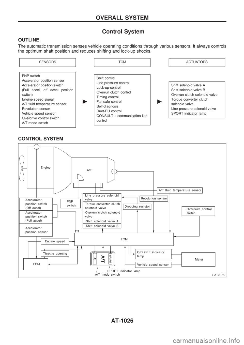
Control System
OUTLINE
The automatic transmission senses vehicle operating conditions through various sensors. It always controls
the optimum shaft position and reduces shifting and lock-up shocks.
SENSORSTCMACTUATORS
PNP switch
Accelerator position sensor
Accelerator position switch
(Full accel, off accel position
switch)
Engine speed signal
A/T fluid temperature sensor
Revolution sensor
Vehicle speed sensor
Overdrive control switch
A/T mode switch
c
Shift control
Line pressure control
Lock-up control
Overrun clutch control
Timing control
Fail-safe control
Self-diagnosis
Duet-EU control
CONSULT-II communication line
control
c
Shift solenoid valve A
Shift solenoid valve B
Overrun clutch solenoid valve
Torque converter clutch
solenoid valve
Line pressure solenoid valve
SPORT indicator lamp
CONTROL SYSTEM
SAT207K
OVERALL SYSTEM
AT-1026
Page 29 of 1033
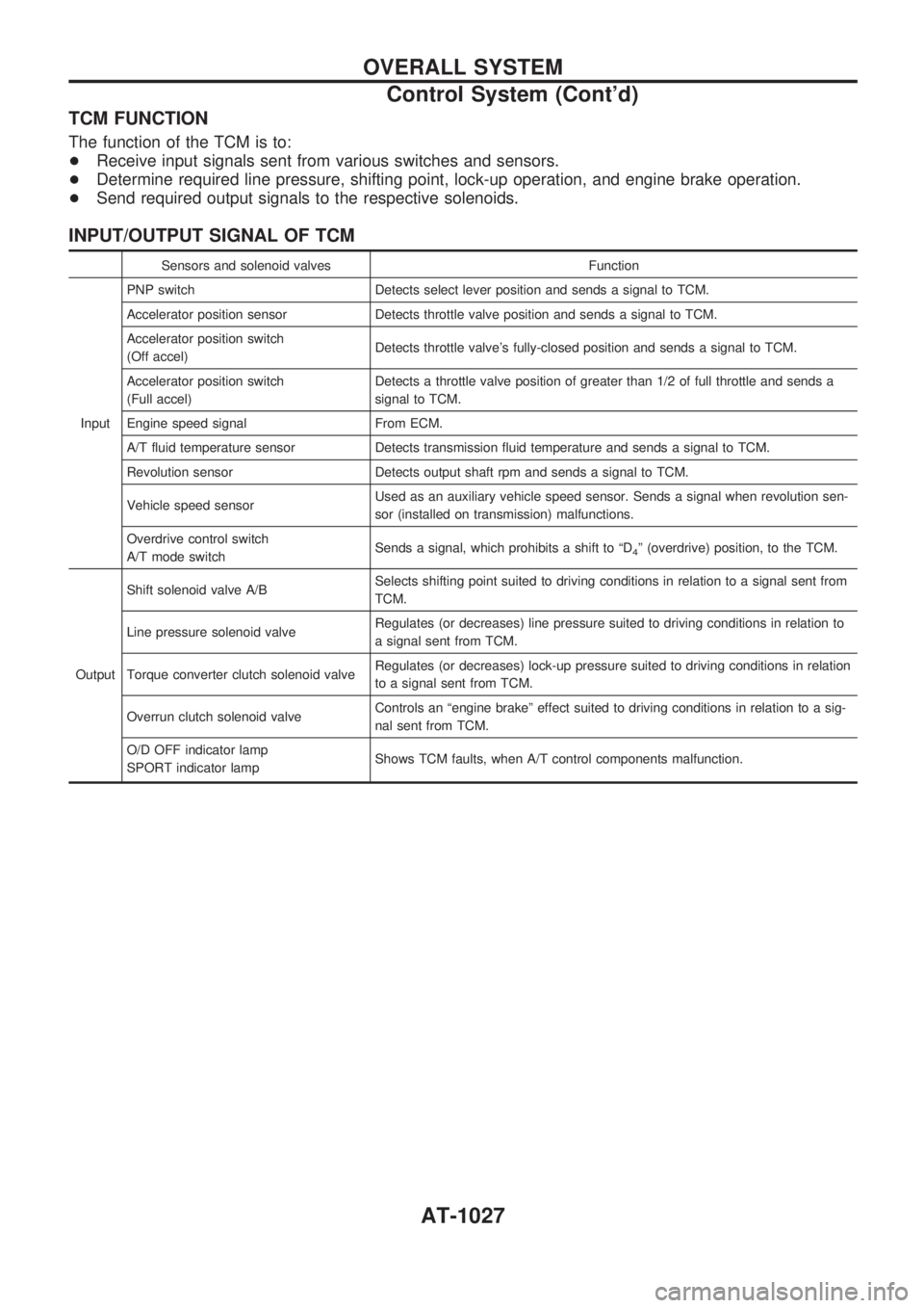
TCM FUNCTION
The function of the TCM is to:
+Receive input signals sent from various switches and sensors.
+Determine required line pressure, shifting point, lock-up operation, and engine brake operation.
+Send required output signals to the respective solenoids.
INPUT/OUTPUT SIGNAL OF TCM
Sensors and solenoid valves Function
InputPNP switch Detects select lever position and sends a signal to TCM.
Accelerator position sensor Detects throttle valve position and sends a signal to TCM.
Accelerator position switch
(Off accel)Detects throttle valve's fully-closed position and sends a signal to TCM.
Accelerator position switch
(Full accel)Detects a throttle valve position of greater than 1/2 of full throttle and sends a
signal to TCM.
Engine speed signal From ECM.
A/T fluid temperature sensor Detects transmission fluid temperature and sends a signal to TCM.
Revolution sensor Detects output shaft rpm and sends a signal to TCM.
Vehicle speed sensorUsed as an auxiliary vehicle speed sensor. Sends a signal when revolution sen-
sor (installed on transmission) malfunctions.
Overdrive control switch
A/T mode switchSends a signal, which prohibits a shift to ªD
4º (overdrive) position, to the TCM.
OutputShift solenoid valve A/BSelects shifting point suited to driving conditions in relation to a signal sent from
TCM.
Line pressure solenoid valveRegulates (or decreases) line pressure suited to driving conditions in relation to
a signal sent from TCM.
Torque converter clutch solenoid valveRegulates (or decreases) lock-up pressure suited to driving conditions in relation
to a signal sent from TCM.
Overrun clutch solenoid valveControls an ªengine brakeº effect suited to driving conditions in relation to a sig-
nal sent from TCM.
O/D OFF indicator lamp
SPORT indicator lampShows TCM faults, when A/T control components malfunction.
OVERALL SYSTEM
Control System (Cont'd)
AT-1027
Page 30 of 1033
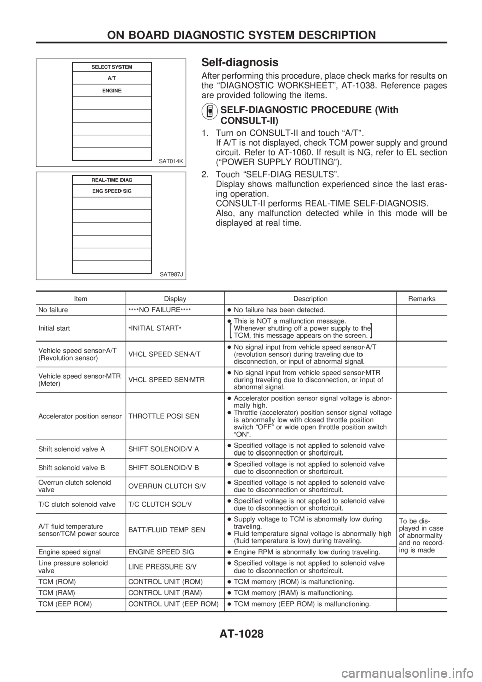
Self-diagnosis
After performing this procedure, place check marks for results on
the ªDIAGNOSTIC WORKSHEETº, AT-1038. Reference pages
are provided following the items.
SELF-DIAGNOSTIC PROCEDURE (With
CONSULT-II)
1. Turn on CONSULT-II and touch ªA/Tº.
If A/T is not displayed, check TCM power supply and ground
circuit. Refer to AT-1060. If result is NG, refer to EL section
(ªPOWER SUPPLY ROUTINGº).
2. Touch ªSELF-DIAG RESULTSº.
Display shows malfunction experienced since the last eras-
ing operation.
CONSULT-II performs REAL-TIME SELF-DIAGNOSIS.
Also, any malfunction detected while in this mode will be
displayed at real time.
Item Display Description Remarks
No failure
****NO FAILURE
****+No failure has been detected.
Initial start
*INITIAL START
*+This is NOT a malfunction message.
Whenever shutting off a power supply to the
TCM, this message appears on the screen.
[]
Vehicle speed sensorzA/T
(Revolution sensor)VHCL SPEED SENzA/T+No signal input from vehicle speed sensorzA/T
(revolution sensor) during traveling due to
disconnection, or input of abnormal signal.
Vehicle speed sensorzMTR
(Meter)VHCL SPEED SENzMTR+No signal input from vehicle speed sensorzMTR
during traveling due to disconnection, or input of
abnormal signal.
Accelerator position sensor THROTTLE POSI SEN+Accelerator position sensor signal voltage is abnor-
mally high.
+Throttle (accelerator) position sensor signal voltage
is abnormally low with closed throttle position
switch ªOFFº or wide open throttle position switch
ªONº.
Shift solenoid valve A SHIFT SOLENOID/V A+Specified voltage is not applied to solenoid valve
due to disconnection or shortcircuit.
Shift solenoid valve B SHIFT SOLENOID/V B+Specified voltage is not applied to solenoid valve
due to disconnection or shortcircuit.
Overrun clutch solenoid
valveOVERRUN CLUTCH S/V+Specified voltage is not applied to solenoid valve
due to disconnection or shortcircuit.
T/C clutch solenoid valve T/C CLUTCH SOL/V+Specified voltage is not applied to solenoid valve
due to disconnection or shortcircuit.
A/T fluid temperature
sensor/TCM power sourceBATT/FLUID TEMP SEN+Supply voltage to TCM is abnormally low during
traveling.
+Fluid temperature signal voltage is abnormally high
(fluid temperature is low) during traveling.To be dis-
played in case
of abnormality
and no record-
ing is made
Engine speed signal ENGINE SPEED SIG+Engine RPM is abnormally low during traveling.
Line pressure solenoid
valveLINE PRESSURE S/V+Specified voltage is not applied to solenoid valve
due to disconnection or shortcircuit.
TCM (ROM) CONTROL UNIT (ROM)+TCM memory (ROM) is malfunctioning.
TCM (RAM) CONTROL UNIT (RAM)+TCM memory (RAM) is malfunctioning.
TCM (EEP ROM) CONTROL UNIT (EEP ROM)+TCM memory (EEP ROM) is malfunctioning.
SAT014K
SAT987J
ON BOARD DIAGNOSTIC SYSTEM DESCRIPTION
AT-1028
Page 36 of 1033
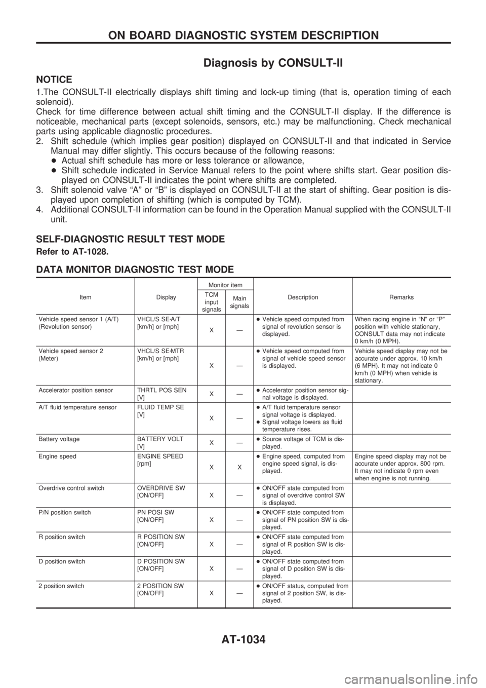
Diagnosis by CONSULT-II
NOTICE
1.The CONSULT-II electrically displays shift timing and lock-up timing (that is, operation timing of each
solenoid).
Check for time difference between actual shift timing and the CONSULT-II display. If the difference is
noticeable, mechanical parts (except solenoids, sensors, etc.) may be malfunctioning. Check mechanical
parts using applicable diagnostic procedures.
2. Shift schedule (which implies gear position) displayed on CONSULT-II and that indicated in Service
Manual may differ slightly. This occurs because of the following reasons:
+Actual shift schedule has more or less tolerance or allowance,
+Shift schedule indicated in Service Manual refers to the point where shifts start. Gear position dis-
played on CONSULT-II indicates the point where shifts are completed.
3. Shift solenoid valve ªAº or ªBº is displayed on CONSULT-II at the start of shifting. Gear position is dis-
played upon completion of shifting (which is computed by TCM).
4. Additional CONSULT-II information can be found in the Operation Manual supplied with the CONSULT-II
unit.
SELF-DIAGNOSTIC RESULT TEST MODE
Refer to AT-1028.
DATA MONITOR DIAGNOSTIC TEST MODE
Item DisplayMonitor item
Description Remarks TCM
input
signalsMain
signals
Vehicle speed sensor 1 (A/T)
(Revolution sensor)VHCL/S SEzA/T
[km/h] or [mph]
XÐ+Vehicle speed computed from
signal of revolution sensor is
displayed.When racing engine in ªNº or ªPº
position with vehicle stationary,
CONSULT data may not indicate
0 km/h (0 MPH).
Vehicle speed sensor 2
(Meter)VHCL/S SEzMTR
[km/h] or [mph]
XÐ+Vehicle speed computed from
signal of vehicle speed sensor
is displayed.Vehicle speed display may not be
accurate under approx. 10 km/h
(6 MPH). It may not indicate 0
km/h (0 MPH) when vehicle is
stationary.
Accelerator position sensor THRTL POS SEN
[V]XÐ+Accelerator position sensor sig-
nal voltage is displayed.
A/T fluid temperature sensor FLUID TEMP SE
[V]
XÐ+A/T fluid temperature sensor
signal voltage is displayed.
+Signal voltage lowers as fluid
temperature rises.
Battery voltage BATTERY VOLT
[V]XÐ+Source voltage of TCM is dis-
played.
Engine speed ENGINE SPEED
[rpm]
XX+Engine speed, computed from
engine speed signal, is dis-
played.Engine speed display may not be
accurate under approx. 800 rpm.
It may not indicate 0 rpm even
when engine is not running.
Overdrive control switch OVERDRIVE SW
[ON/OFF] X Ð+ON/OFF state computed from
signal of overdrive control SW
is displayed.
P/N position switch PN POSI SW
[ON/OFF] X Ð+ON/OFF state computed from
signal of PN position SW is dis-
played.
R position switch R POSITION SW
[ON/OFF] X Ð+ON/OFF state computed from
signal of R position SW is dis-
played.
D position switch D POSITION SW
[ON/OFF] X Ð+ON/OFF state computed from
signal of D position SW is dis-
played.
2 position switch 2 POSITION SW
[ON/OFF] X Ð+ON/OFF status, computed from
signal of 2 position SW, is dis-
played.
ON BOARD DIAGNOSTIC SYSTEM DESCRIPTION
AT-1034
Page 40 of 1033
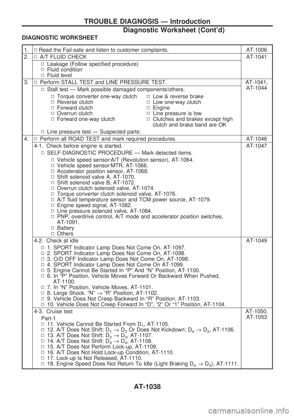
DIAGNOSTIC WORKSHEET
1.NRead the Fail-safe and listen to customer complaints. AT-1006
2.NA/T FLUID CHECK AT-1041
NLeakage (Follow specified procedure)
NFluid condition
NFluid level
3.NPerform STALL TEST and LINE PRESSURE TEST. AT-1041,
AT-1044
NStall test Ð Mark possible damaged components/others.
NTorque converter one-way clutch
NReverse clutch
NForward clutch
NOverrun clutch
NForward one-way clutchNLow & reverse brake
NLow one-way clutch
NEngine
NLine pressure is low
NClutches and brakes except high
clutch and brake band are OK
NLine pressure test Ð Suspected parts:
4.NPerform all ROAD TEST and mark required procedures. AT-1046
4-1. Check before engine is started. AT-1047
NSELF-DIAGNOSTIC PROCEDURE Ð Mark detected items.
NVehicle speed sensorzA/T (Revolution sensor), AT-1064.
NVehicle speed sensorzMTR, AT-1066.
NAccelerator position sensor, AT-1068.
NShift solenoid valve A, AT-1070.
NShift solenoid valve B, AT-1072.
NOverrun clutch solenoid valve, AT-1074.
NTorque converter clutch solenoid valve, AT-1076.
NA/T fluid temperature sensor and TCM power source, AT-1079.
NEngine speed signal, AT-1082.
NLine pressure solenoid valve, AT-1084.
NPNP, overdrive control, A/T mode and accelerator position switches,
AT-1091.
NBattery
NOthers
4-2. Check at idle AT-1049
N1. SPORT Indicator Lamp Does Not Come On, AT-1097.
N2. SPORT Indicator Lamp Does Not Come On, AT-1098.
N3. O/D OFF Indicator Lamp Does Not Come On, AT-1098.
N4. SPORT Indicator Lamp Does Not Come On AT-1099.
N5. Engine Cannot Be Started In ªPº And ªNº Position, AT-1100.
N6. In ªPº Position, Vehicle Moves Forward Or Backward When Pushed,
AT-1100.
N7. In ªNº Position, Vehicle Moves, AT-1101.
N8. Large Shock. ªNº®ªRº Position, AT-1102.
N9. Vehicle Does Not Creep Backward In ªRº Position, AT-1103.
N10. Vehicle Does Not Creep Forward In ªDº, ª2º Or ª1º Position, AT-1104.
4-3. Cruise test AT-1050,
AT-1053
Part-1
N11. Vehicle Cannot Be Started From D
1, AT-1105.
N12. A/T Does Not Shift: D
1®D2Or Does Not Kickdown: D4®D2, AT-1106.
N13. A/T Does Not Shift: D
2®D3, AT-1107.
N14. A/T Does Not Shift: D
3®D4, AT-1108.
N15. A/T Does Not Perform Lock-up, AT-1109.
N16. A/T Does Not Hold Lock-up Condition, AT-1110.
N17. Lock-up Is Not Released, AT-1110.
N18. Engine Speed Does Not Return To Idle (Light Braking D
4®D3), AT-1111.
TROUBLE DIAGNOSIS Ð Introduction
Diagnostic Worksheet (Cont'd)
AT-1038
Page 41 of 1033
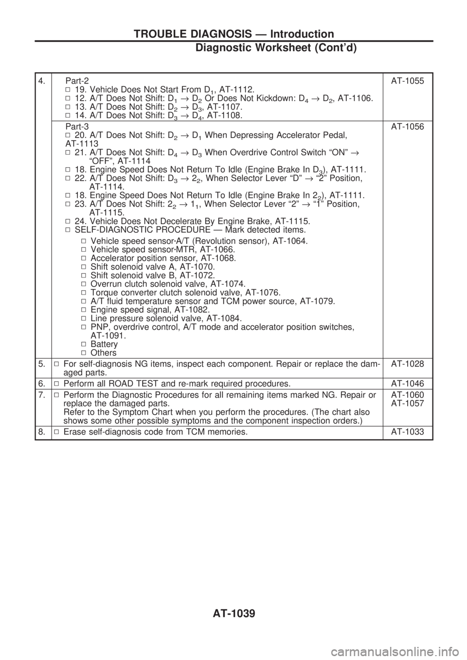
4. Part-2
N19. Vehicle Does Not Start From D
1, AT-1112.
N12. A/T Does Not Shift: D
1®D2Or Does Not Kickdown: D4®D2, AT-1106.
N13. A/T Does Not Shift: D
2®D3, AT-1107.
N14. A/T Does Not Shift: D
3®D4, AT-1108.AT-1055
Part-3
N20. A/T Does Not Shift: D
2®D1When Depressing Accelerator Pedal,
AT-1113
N21. A/T Does Not Shift: D
4®D3When Overdrive Control Switch ªONº®
ªOFFº, AT-1114
N18. Engine Speed Does Not Return To Idle (Engine Brake In D
3), AT-1111.
N22. A/T Does Not Shift: D
3®22, When Selector Lever ªDº®ª2º Position,
AT-1114.
N18. Engine Speed Does Not Return To Idle (Engine Brake In 2
2), AT-1111.
N23. A/T Does Not Shift: 2
2®11, When Selector Lever ª2º®ª1º Position,
AT-1115.
N24. Vehicle Does Not Decelerate By Engine Brake, AT-1115.
NSELF-DIAGNOSTIC PROCEDURE Ð Mark detected items.AT-1056
NVehicle speed sensorzA/T (Revolution sensor), AT-1064.
NVehicle speed sensorzMTR, AT-1066.
NAccelerator position sensor, AT-1068.
NShift solenoid valve A, AT-1070.
NShift solenoid valve B, AT-1072.
NOverrun clutch solenoid valve, AT-1074.
NTorque converter clutch solenoid valve, AT-1076.
NA/T fluid temperature sensor and TCM power source, AT-1079.
NEngine speed signal, AT-1082.
NLine pressure solenoid valve, AT-1084.
NPNP, overdrive control, A/T mode and accelerator position switches,
AT-1091.
NBattery
NOthers
5.NFor self-diagnosis NG items, inspect each component. Repair or replace the dam-
aged parts.AT-1028
6.NPerform all ROAD TEST and re-mark required procedures. AT-1046
7.NPerform the Diagnostic Procedures for all remaining items marked NG. Repair or
replace the damaged parts.
Refer to the Symptom Chart when you perform the procedures. (The chart also
shows some other possible symptoms and the component inspection orders.)AT-1060
AT-1057
8.NErase self-diagnosis code from TCM memories. AT-1033
TROUBLE DIAGNOSIS Ð Introduction
Diagnostic Worksheet (Cont'd)
AT-1039