2000 DODGE NEON suspension
[x] Cancel search: suspensionPage 61 of 1285
hex on the end of the strut shaft. While holding the
strut shaft from turning, tighten the strut shaft
retaining nut to a torque of 75 N´m (55 ft. lbs.).
(10) Slowly release the tension from the coil spring
by backing off the compressor drive completely. As
the tension is relieved, make sure the upper mount's
seat aligns properly with the coil spring.
(11) Verify the arrow on the upper mount is point-
ing in the same direction as the strut clevis bracket
as mentioned in step 9.
(12) Remove the clamp from the lower end of the
coil spring and strut. Push back the spring compres-
sor upper and lower hooks, then remove the strut
assembly from the spring compressor.
(13) Install the strut assembly on the vehicle.
Refer to REMOVAL AND INSTALLATION in this
section for the required procedure.
SPECIFICATIONS
REAR SUSPENSION FASTENER TORQUE
SPECIFICATIONS
DESCRIPTION TORQUE
STRUT ASSEMBLY:
Tower Attaching Nuts..... 34N´m(300 in. lbs.)
Knuckle Attaching Bolts.... 88N´m(65ft.lbs.)
Strut Assembly Shaft Nut . . . 75 N´m (55 ft. lbs.)
Brake Hose Bracket Mounting Bolt..... 31N´m
(275 in. lbs.)
KNUCKLE:
Brake Support Plate Mounting Bolts.... 75N´m
(55 ft. lbs.)
Disc Brake Adapter Mounting Bolts.... 75N´m
(55 ft. lbs.)
HUB AND BEARING:
To Knuckle Retaining Nut........... 217N´m
(160 ft. lbs.)
Wheel Mounting Nuts...........109-150 N´m
(80-110 ft. lbs.)
LATERAL ARM:
Nut At Crossmember....... 88N´m(65ft.lbs.)
Nut At Knuckle........... 95N´m(70ft.lbs.)
TENSION STRUT:
Rear Nut................ 95N´m(70ft.lbs.)
Frame Rail Bolts.......... 95N´m(70ft.lbs.)
Parking Brake Cable Nut . . 28 N´m (250 in. lbs.)
STABILIZER BAR:
Cushion Retainer Bolts.... 34N´m(300 in. lbs.)
Link Bolt Nut........... 23N´m(200 in. lbs.)
SPECIAL TOOLS
REAR SUSPENSION
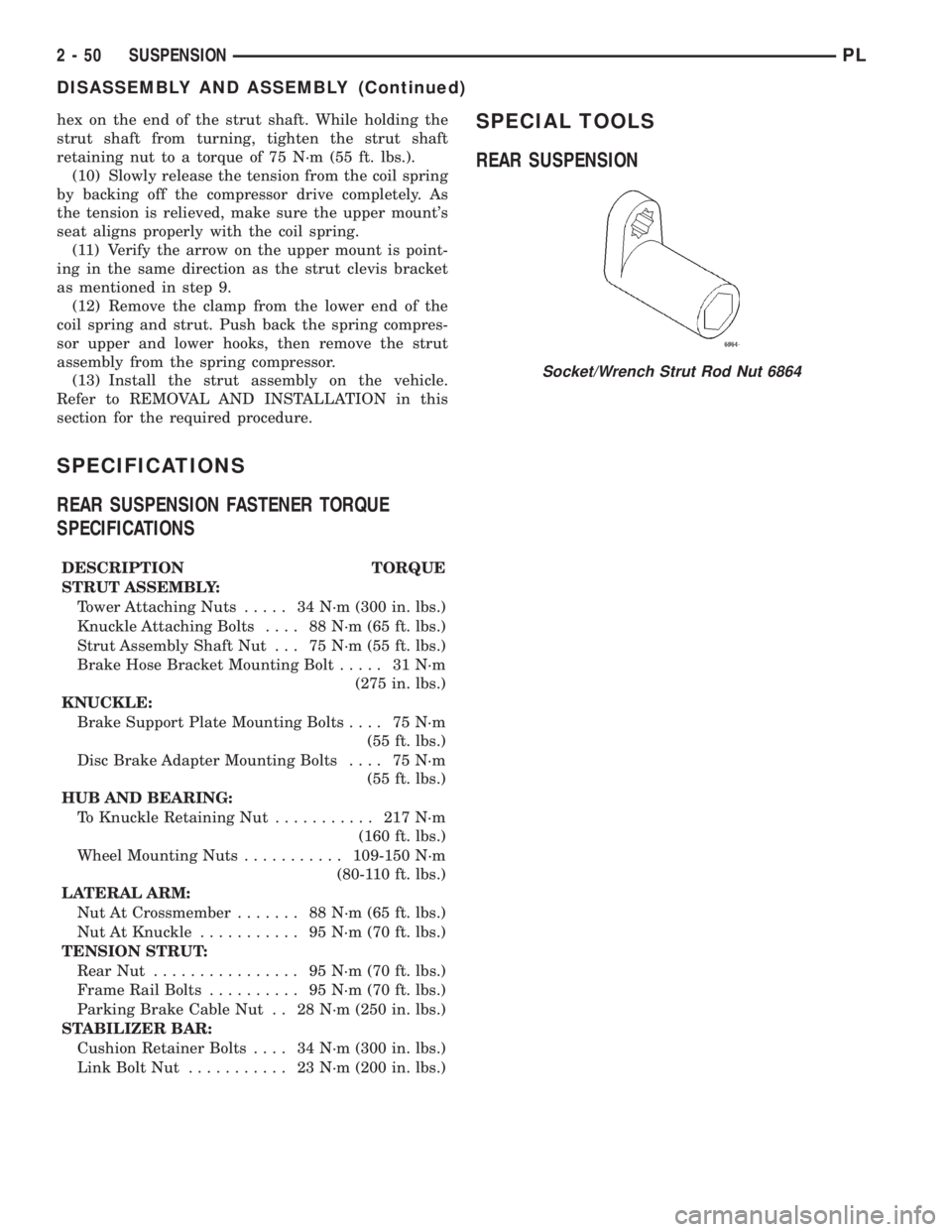
Socket/Wrench Strut Rod Nut 6864
2 - 50 SUSPENSIONPL
DISASSEMBLY AND ASSEMBLY (Continued)
Page 66 of 1285
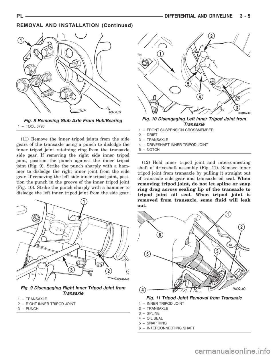
(11) Remove the inner tripod joints from the side
gears of the transaxle using a punch to dislodge the
inner tripod joint retaining ring from the transaxle
side gear. If removing the right side inner tripod
joint, position the punch against the inner tripod
joint (Fig. 9). Strike the punch sharply with a ham-
mer to dislodge the right inner joint from the side
gear. If removing the left side inner tripod joint, posi-
tion the punch in the groove of the inner tripod joint
(Fig. 10). Strike the punch sharply with a hammer to
dislodge the left inner tripod joint from the side gear.(12) Hold inner tripod joint and interconnecting
shaft of driveshaft assembly (Fig. 11). Remove inner
tripod joint from transaxle by pulling it straight out
of transaxle side gear and transaxle oil seal.When
removing tripod joint, do not let spline or snap
ring drag across sealing lip of the transaxle to
tripod joint oil seal. When tripod joint is
removed from transaxle, some fluid will leak
out.
Fig. 8 Removing Stub Axle From Hub/Bearing
1 ± TOOL 6790
Fig. 9 Disengaging Right Inner Tripod Joint from
Transaxle
1 ± TRANSAXLE
2 ± RIGHT INNER TRIPOD JOINT
3 ± PUNCH
Fig. 10 Disengaging Left Inner Tripod Joint from
Transaxle
1 ± FRONT SUSPENSION CROSSMEMBER
2 ± DRIFT
3 ± TRANSAXLE
4 ± DRIVESHAFT INNER TRIPOD JOINT
5 ± NOTCH
Fig. 11 Tripod Joint Removal from Transaxle
1 ± INNER TRIPOD JOINT
2 ± TRANSAXLE
3 ± SPLINE
4 ± OIL SEAL
5 ± SNAP RING
6 ± INTERCONNECTING SHAFT
PLDIFFERENTIAL AND DRIVELINE 3 - 5
REMOVAL AND INSTALLATION (Continued)
Page 83 of 1285
Proportioning valves balance front to rear braking
by controlling the brake fluid hydraulic pressure to
the rear brakes. Under light pedal application, the
proportioning valve allows normal fluid flow to the
rear brakes. Under higher pedal effort, the valve
reduces fluid pressure to the rear brakes.
The non-antilock master cylinder is a four-outlet
design with two screw-in proportioning valves
attached directly to the master cylinder housing (Fig.
3). One proportioning valve controls each rear brake.
BRAKE TUBES AND HOSES
The purpose of the brake tubes and flex hoses is to
transfer the pressurized brake fluid developed by the
master cylinder to the brakes at each wheel of the
vehicle. The flex hoses connect the chassis brake
tubes, which are mounted to the vehicle's underbody,
to the brake at each wheel, allowing for movement of
the vehicle's suspension. The brake tubes are steel
with a corrosion-resistant nylon coating applied to
the external surfaces. The flex hoses are made of
reinforced rubber.
DISC BRAKES (FRONT)
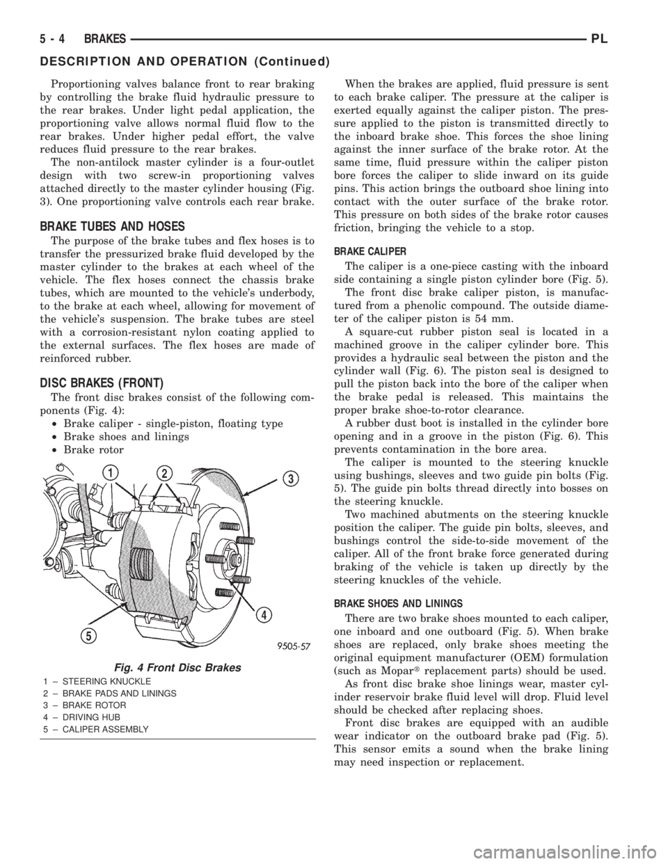
The front disc brakes consist of the following com-
ponents (Fig. 4):
²Brake caliper - single-piston, floating type
²Brake shoes and linings
²Brake rotorWhen the brakes are applied, fluid pressure is sent
to each brake caliper. The pressure at the caliper is
exerted equally against the caliper piston. The pres-
sure applied to the piston is transmitted directly to
the inboard brake shoe. This forces the shoe lining
against the inner surface of the brake rotor. At the
same time, fluid pressure within the caliper piston
bore forces the caliper to slide inward on its guide
pins. This action brings the outboard shoe lining into
contact with the outer surface of the brake rotor.
This pressure on both sides of the brake rotor causes
friction, bringing the vehicle to a stop.
BRAKE CALIPER
The caliper is a one-piece casting with the inboard
side containing a single piston cylinder bore (Fig. 5).
The front disc brake caliper piston, is manufac-
tured from a phenolic compound. The outside diame-
ter of the caliper piston is 54 mm.
A square-cut rubber piston seal is located in a
machined groove in the caliper cylinder bore. This
provides a hydraulic seal between the piston and the
cylinder wall (Fig. 6). The piston seal is designed to
pull the piston back into the bore of the caliper when
the brake pedal is released. This maintains the
proper brake shoe-to-rotor clearance.
A rubber dust boot is installed in the cylinder bore
opening and in a groove in the piston (Fig. 6). This
prevents contamination in the bore area.
The caliper is mounted to the steering knuckle
using bushings, sleeves and two guide pin bolts (Fig.
5). The guide pin bolts thread directly into bosses on
the steering knuckle.
Two machined abutments on the steering knuckle
position the caliper. The guide pin bolts, sleeves, and
bushings control the side-to-side movement of the
caliper. All of the front brake force generated during
braking of the vehicle is taken up directly by the
steering knuckles of the vehicle.
BRAKE SHOES AND LININGS
There are two brake shoes mounted to each caliper,
one inboard and one outboard (Fig. 5). When brake
shoes are replaced, only brake shoes meeting the
original equipment manufacturer (OEM) formulation
(such as Mopartreplacement parts) should be used.
As front disc brake shoe linings wear, master cyl-
inder reservoir brake fluid level will drop. Fluid level
should be checked after replacing shoes.
Front disc brakes are equipped with an audible
wear indicator on the outboard brake pad (Fig. 5).
This sensor emits a sound when the brake lining
may need inspection or replacement.
Fig. 4 Front Disc Brakes
1 ± STEERING KNUCKLE
2 ± BRAKE PADS AND LININGS
3 ± BRAKE ROTOR
4 ± DRIVING HUB
5 ± CALIPER ASSEMBLY
5 - 4 BRAKESPL
DESCRIPTION AND OPERATION (Continued)
Page 85 of 1285
DISC BRAKES (REAR)
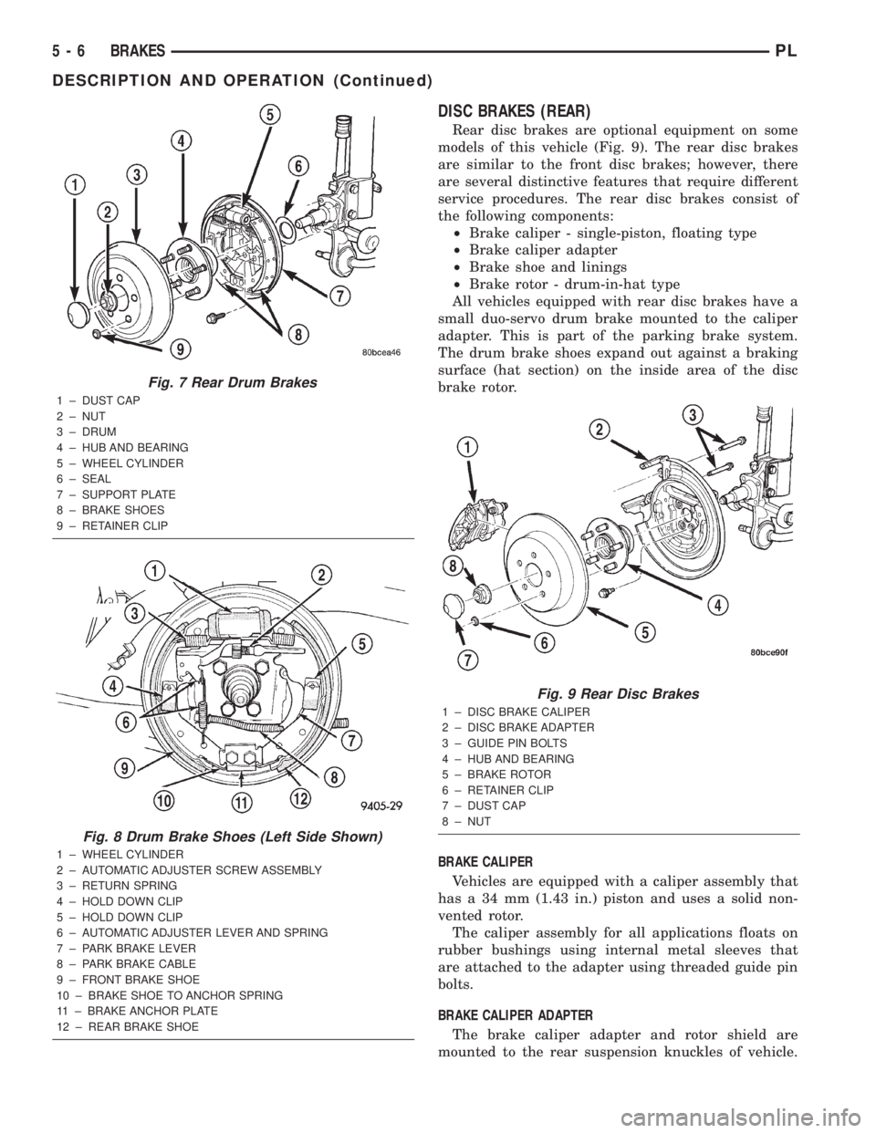
Rear disc brakes are optional equipment on some
models of this vehicle (Fig. 9). The rear disc brakes
are similar to the front disc brakes; however, there
are several distinctive features that require different
service procedures. The rear disc brakes consist of
the following components:
²Brake caliper - single-piston, floating type
²Brake caliper adapter
²Brake shoe and linings
²Brake rotor - drum-in-hat type
All vehicles equipped with rear disc brakes have a
small duo-servo drum brake mounted to the caliper
adapter. This is part of the parking brake system.
The drum brake shoes expand out against a braking
surface (hat section) on the inside area of the disc
brake rotor.
BRAKE CALIPER
Vehicles are equipped with a caliper assembly that
has a 34 mm (1.43 in.) piston and uses a solid non-
vented rotor.
The caliper assembly for all applications floats on
rubber bushings using internal metal sleeves that
are attached to the adapter using threaded guide pin
bolts.
BRAKE CALIPER ADAPTER
The brake caliper adapter and rotor shield are
mounted to the rear suspension knuckles of vehicle.
Fig. 7 Rear Drum Brakes
1 ± DUST CAP
2 ± NUT
3 ± DRUM
4 ± HUB AND BEARING
5 ± WHEEL CYLINDER
6 ± SEAL
7 ± SUPPORT PLATE
8 ± BRAKE SHOES
9 ± RETAINER CLIP
Fig. 8 Drum Brake Shoes (Left Side Shown)
1 ± WHEEL CYLINDER
2 ± AUTOMATIC ADJUSTER SCREW ASSEMBLY
3 ± RETURN SPRING
4 ± HOLD DOWN CLIP
5 ± HOLD DOWN CLIP
6 ± AUTOMATIC ADJUSTER LEVER AND SPRING
7 ± PARK BRAKE LEVER
8 ± PARK BRAKE CABLE
9 ± FRONT BRAKE SHOE
10 ± BRAKE SHOE TO ANCHOR SPRING
11 ± BRAKE ANCHOR PLATE
12 ± REAR BRAKE SHOE
Fig. 9 Rear Disc Brakes
1 ± DISC BRAKE CALIPER
2 ± DISC BRAKE ADAPTER
3 ± GUIDE PIN BOLTS
4 ± HUB AND BEARING
5 ± BRAKE ROTOR
6 ± RETAINER CLIP
7 ± DUST CAP
8 ± NUT
5 - 6 BRAKESPL
DESCRIPTION AND OPERATION (Continued)
Page 90 of 1285
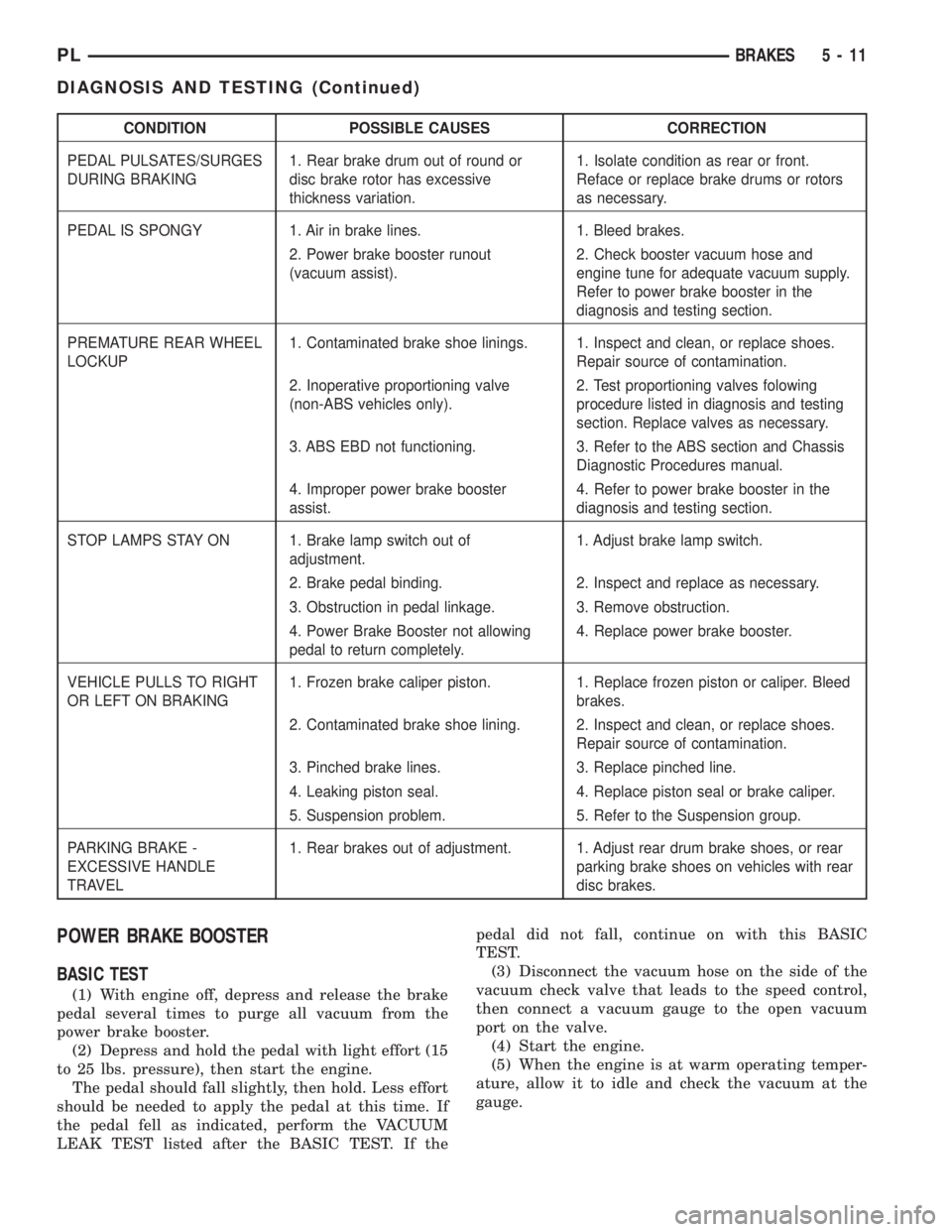
CONDITION POSSIBLE CAUSES CORRECTION
PEDAL PULSATES/SURGES
DURING BRAKING1. Rear brake drum out of round or
disc brake rotor has excessive
thickness variation.1. Isolate condition as rear or front.
Reface or replace brake drums or rotors
as necessary.
PEDAL IS SPONGY 1. Air in brake lines. 1. Bleed brakes.
2. Power brake booster runout
(vacuum assist).2. Check booster vacuum hose and
engine tune for adequate vacuum supply.
Refer to power brake booster in the
diagnosis and testing section.
PREMATURE REAR WHEEL
LOCKUP1. Contaminated brake shoe linings. 1. Inspect and clean, or replace shoes.
Repair source of contamination.
2. Inoperative proportioning valve
(non-ABS vehicles only).2. Test proportioning valves folowing
procedure listed in diagnosis and testing
section. Replace valves as necessary.
3. ABS EBD not functioning. 3. Refer to the ABS section and Chassis
Diagnostic Procedures manual.
4. Improper power brake booster
assist.4. Refer to power brake booster in the
diagnosis and testing section.
STOP LAMPS STAY ON 1. Brake lamp switch out of
adjustment.1. Adjust brake lamp switch.
2. Brake pedal binding. 2. Inspect and replace as necessary.
3. Obstruction in pedal linkage. 3. Remove obstruction.
4. Power Brake Booster not allowing
pedal to return completely.4. Replace power brake booster.
VEHICLE PULLS TO RIGHT
OR LEFT ON BRAKING1. Frozen brake caliper piston. 1. Replace frozen piston or caliper. Bleed
brakes.
2. Contaminated brake shoe lining. 2. Inspect and clean, or replace shoes.
Repair source of contamination.
3. Pinched brake lines. 3. Replace pinched line.
4. Leaking piston seal. 4. Replace piston seal or brake caliper.
5. Suspension problem. 5. Refer to the Suspension group.
PARKING BRAKE -
EXCESSIVE HANDLE
TRAVEL1. Rear brakes out of adjustment. 1. Adjust rear drum brake shoes, or rear
parking brake shoes on vehicles with rear
disc brakes.
POWER BRAKE BOOSTER
BASIC TEST
(1) With engine off, depress and release the brake
pedal several times to purge all vacuum from the
power brake booster.
(2) Depress and hold the pedal with light effort (15
to 25 lbs. pressure), then start the engine.
The pedal should fall slightly, then hold. Less effort
should be needed to apply the pedal at this time. If
the pedal fell as indicated, perform the VACUUM
LEAK TEST listed after the BASIC TEST. If thepedal did not fall, continue on with this BASIC
TEST.
(3) Disconnect the vacuum hose on the side of the
vacuum check valve that leads to the speed control,
then connect a vacuum gauge to the open vacuum
port on the valve.
(4) Start the engine.
(5) When the engine is at warm operating temper-
ature, allow it to idle and check the vacuum at the
gauge.
PLBRAKES 5 - 11
DIAGNOSIS AND TESTING (Continued)
Page 93 of 1285
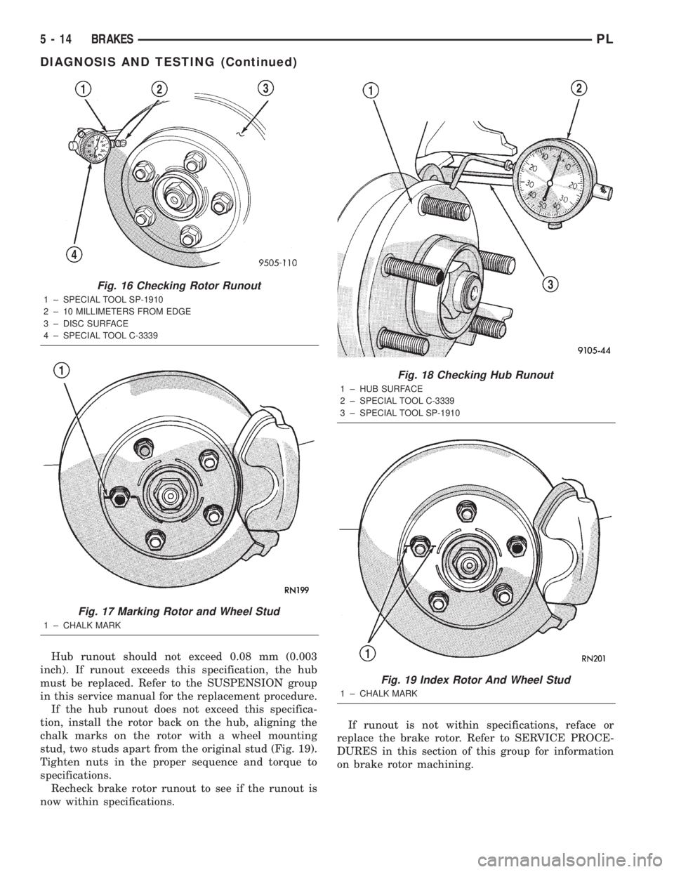
Hub runout should not exceed 0.08 mm (0.003
inch). If runout exceeds this specification, the hub
must be replaced. Refer to the SUSPENSION group
in this service manual for the replacement procedure.
If the hub runout does not exceed this specifica-
tion, install the rotor back on the hub, aligning the
chalk marks on the rotor with a wheel mounting
stud, two studs apart from the original stud (Fig. 19).
Tighten nuts in the proper sequence and torque to
specifications.
Recheck brake rotor runout to see if the runout is
now within specifications.If runout is not within specifications, reface or
replace the brake rotor. Refer to SERVICE PROCE-
DURES in this section of this group for information
on brake rotor machining.
Fig. 16 Checking Rotor Runout
1 ± SPECIAL TOOL SP-1910
2 ± 10 MILLIMETERS FROM EDGE
3 ± DISC SURFACE
4 ± SPECIAL TOOL C-3339
Fig. 17 Marking Rotor and Wheel Stud
1 ± CHALK MARK
Fig. 18 Checking Hub Runout
1 ± HUB SURFACE
2 ± SPECIAL TOOL C-3339
3 ± SPECIAL TOOL SP-1910
Fig. 19 Index Rotor And Wheel Stud
1 ± CHALK MARK
5 - 14 BRAKESPL
DIAGNOSIS AND TESTING (Continued)
Page 126 of 1285
(11) Remove the 4 brake support plate mounting
bolts and washers. Separate brake support plate
from rear suspension knuckle.
(12) Remove the brake wheel cylinder attaching
bolts.
(13) Remove the brake wheel cylinder from the
brake support plate.
INSTALLATION
(1) Install a new O-ring at the mating surface of
the wheel cylinder-to-brake support plate.
NOTE: When installing wheel cylinder on brake
support plate, be sure it is positioned squarely (hor-
izontal) to the brake support plate.(2) Install the wheel cylinder onto brake support
plate. Tighten the attaching bolts to a torque of 13
N´m (115 in. lbs.).
(3) Install the brake support plate and gasket on
rear suspension knuckle. Tighten the support plate
mounting bolts to a torque of 75 N´m (55 ft. lbs.).
(4) Insert the parking brake cable into its mount-
ing hole in the brake support plate. Push the cable
housing in until the retainer's fingers lock into place.
(5) Hand start the brake flex hose tube fitting to
the wheel cylinder. Tighten the tube nut to a torque
of 17 N´m (145 in. lbs.).
(6) Attach the parking brake cable to the parking
brake actuator.
(7) Install the rear brake shoe assemblies on the
brake support plate.
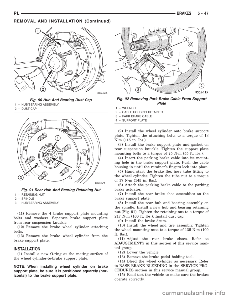
(8) Install the rear hub and bearing assembly on
the spindle. Install a new hub and bearing retaining
nut (Fig. 91). Tighten the retaining nut to a torque of
217 N´m (160 ft. lbs.). Install dust cap.
(9) Install the brake drum.
(10) Install the wheel and tire assembly. Tighten
the wheel mounting nuts to a torque of 135 N´m (100
ft. lbs.).
(11) Adjust the rear brake shoes. Refer to
ADJUSTMENTS in this section of this service man-
ual group.
(12) Lower the vehicle.
(13) Remove the brake pedal holding tool.
(14) Bleed the wheel cylinder as necessary. Refer
to BASE BRAKE BLEEDING in the SERVICE PRO-
CEDURES section in this service manual group.
(15) Road test the vehicle to make sure the brakes
operate correctly.
Fig. 90 Hub And Bearing Dust Cap
1 ± HUB/BEARING ASSEMBLY
2 ± DUST CAP
Fig. 91 Rear Hub And Bearing Retaining Nut
1 ± RETAINING NUT
2 ± SPINDLE
3 ± HUB/BEARING ASSEMBLY
Fig. 92 Removing Park Brake Cable From Support
Plate
1 ± WRENCH
2 ± CABLE HOUSING RETAINER
3 ± PARK BRAKE CABLE
4 ± SUPPORT PLATE
PLBRAKES 5 - 47
REMOVAL AND INSTALLATION (Continued)
Page 145 of 1285
NOISE AND BRAKE PEDAL FEEL
During ABS braking, some brake pedal movement
may be felt. In addition, ABS braking will create
ticking, popping, or groaning noises heard by the
driver. This is normal and is due to pressurized fluid
being transferred between the master cylinder and
the brakes. If ABS operation occurs during hard
braking, some pulsation may be felt in the vehicle
body due to fore-and-aft movement of the suspension
as brake pressures are modulated.
At the end of an ABS stop, ABS is turned off when
the vehicle is slowed to a speed of 3±4 mph. There
may be a slight brake pedal drop anytime that the
ABS is deactivated, such as at the end of the stop
when the vehicle speed is less than 3 mph or during
an ABS stop where ABS is no longer required. These
conditions exist when a vehicle is being stopped on a
road surface with patches of ice, loose gravel, or sand
on it. Also, stopping a vehicle on a bumpy road sur-
face activates ABS because of the wheel hop caused
by the bumps.
TIRE NOISE AND MARKS
Although the ABS system prevents complete wheel
lockup, some wheel slip is desired in order to achieve
optimum braking performance. Wheel slip is defined
as follows: 0 percent slip means the wheel is rolling
freely and 100 percent slip means the wheel is fully
locked. During brake pressure modulation, wheel slip
is allowed to reach up to 25±30 percent. This means
that the wheel rolling velocity is 25±30 percent less
than that of a free rolling wheel at a given vehicle
speed. This slip may result in some tire chirping,
depending on the road surface. This sound should not
be interpreted as total wheel lockup.
Complete wheel lockup normally leaves black tire
marks on dry pavement. The ABS will not leave dark
black tire marks since the wheel never reaches a
fully locked condition. However, tire marks may be
noticeable as light patched marks.
START-UP CYCLE
When the ignition is turned on, a popping sound
and a slight brake pedal movement may be noticed.
The ABS warning lamp will also be on for up to 5
seconds after the ignition is turned on. When the
vehicle is first driven off, a humming may be heard
or felt by the driver at approximately 20±40 kph
(12±25 mph). All of these conditions are a normal
function of ABS as the system is performing a diag-
nosis check.
PREMATURE ABS CYCLING
Symptoms of premature ABS cycling include: click-
ing sounds from the solenoid valves; pump/motor
running; and pulsations in the brake pedal. Prema-ture ABS cycling can occur at any braking rate of the
vehicle and on any type of road surface. Neither the
red BRAKE warning lamp, nor the amber ABS warn-
ing lamp, illuminate and no fault codes are stored in
the CAB.
Premature ABS cycling is a condition that needs to
be correctly assessed when diagnosing problems with
the antilock brake system. It may be necessary to use
a DRB scan tool to detect and verify premature ABS
cycling.
Check the following common causes when diagnos-
ing premature ABS cycling: damaged tone wheels;
incorrect tone wheels; damaged steering knuckle
wheel speed sensor mounting bosses; loose wheel
speed sensor mounting bolts; excessive tone wheel
runout; or an excessively large tone wheel-to-wheel
speed sensor air gap. Give special attention to these
components when diagnosing a vehicle exhibiting
premature ABS cycling.
After diagnosing the defective component, repair or
replace it as required. When the component repair or
replacement is completed, test drive the vehicle to
verify that premature ABS cycling has been cor-
rected.
ANTILOCK BRAKE SYSTEM COMPONENTS
The following is a detailed description of the
antilock brake system components. For information
on servicing base brake system components used in
conjunction with these components, see the BASE
BRAKE SYSTEM found at the beginning of this ser-
vice manual group.
MASTER CYLINDER
A vehicle equipped with ABS uses a different mas-
ter cylinder than a vehicle that is not equipped with
ABS. Vehicles equipped with ABS use a center port
master cylinder with only two outlet ports (Fig. 1).
The brake tubes from the primary and secondary
outlet ports on the master cylinder go directly to the
integrated control unit (ICU).
The master cylinder mounts to the power brake
booster in the same manner a non-ABS master cylin-
der does.
INTEGRATED CONTROL UNIT (ICU)
The hydraulic control unit (HCU) and the control-
ler antilock brake (CAB) used with this antilock
brake system are combined (integrated) into one
unit, which is called the integrated control unit (ICU)
(Fig. 2). The ICU is located on the driver's side of the
vehicle, and is mounted to the left front frame rail
below the master cylinder (Fig. 1).
5 - 66 BRAKESPL
DESCRIPTION AND OPERATION (Continued)