2000 DODGE NEON suspension
[x] Cancel search: suspensionPage 155 of 1285
junction block. A label on the underside of the PDC
cover identifies the locations of the ABS fuses.
(2) Inspect the 25-way electrical connector at the
CAB for damaged, spread, or backed-out wiring ter-
minals. Verify that the 25-way connector is fully
inserted in the socket of the CAB. Be sure that wires
are not stretched tight or pulled out of the connector.
(3) Verify that all the wheel speed sensor connec-
tions are secure.
(4) Look for poor mating of connector halves or ter-
minals not fully seated in the connector body.
(5)
Check for improperly formed or damaged termi-
nals. All connector terminals in a suspect circuit should
be carefully reformed to increase contact tension.
(6) Look for poor terminal-to-wire connections.
This requires removing the terminal from the connec-
tor body to inspect it.
(7) Verify pin presence in the connector assembly
(8) Check for proper ground connections. Check all
ground connections for signs of corrosion, loose fas-
teners, or other potential defects. Refer to the wiring
diagrams for ground locations.
(9) Look for problems with the main power sources
of the vehicle. Inspect the battery, generator, ignition
circuits and other related relays and fuses.
If a visual check does not find the cause of the
problem, operate the car in an attempt to duplicate
the condition and record any trouble codes.
Most failures of the ABS disable the ABS function
for the entire ignition cycle even if the fault clears
before key-off. There are some failure conditions,
however, that allow ABS operation to resume during
the ignition cycle in which the trouble occurred even
if the trouble conditions are no longer present.
The following trouble conditions may result in
intermittent illumination of the amber ABS warning
lamp.
²Low system voltage. If Low System Voltage is
detected by the CAB, the CAB will turn on the ABS
Warning Lamp until normal system voltage is
achieved. Once normal voltage is seen at the CAB,
normal operation resumes.
²High system voltage. If high system voltage is
detected by the CAB, the CAB will turn on the
Amber ABS Warning Lamp until normal system volt-
age is achieved. Once normal voltage is again
detected by the CAB, normal ABS operation resumes.
Additional possible causes that may result in the
illumination of the amber ABS warning lamp are as
follows:
²Any condition that interrupts electrical current
to the CAB may cause the amber ABS warning lamp
to turn on intermittently.
²If PCI communication between the body control-
ler and the CAB is interrupted, the body controller
can turn on the amber ABS warning lamp.
TONE WHEEL
Tone wheels can cause erratic wheel speed sensor
signals. Inspect tone wheels for the following possible
causes:
²missing, chipped, or broken teeth
²contact with the wheel speed sensor
²wheel speed sensor to tone wheel alignment
²wheel speed sensor to tone wheel clearance
²excessive tone wheel runout
²tone wheel loose on its mounting surface
If a front tone wheel is found to need replacement,
the drive shaft must be replaced. No attempt should
be made to replace just the tone wheel. Refer to the
DIFFERENTIAL AND DRIVELINE group in this
service manual for removal and installation.
If a rear tone wheel is found to need replacement,
the rear hub and bearing must be replaced. No
attempt should be made to replace just the tone
wheel. Refer to the SUSPENSION group in this ser-
vice manual for removal and installation.
If wheel speed sensor to tone wheel contact is evi-
dent, determine the cause and correct it before
replacing the wheel speed sensor or tone wheel.
Check the gap between the speed sensor head and
the tone wheel to ensure it is within specifications.
Refer to SPECIFICATIONS in this section of the ser-
vice manual for the minimum and maximum wheel
speed sensor to tone wheel clearance.
Excessive wheel speed sensor runout can cause
erratic wheel speed sensor signals. Refer to SPECI-
FICATIONS in this section of the service manual for
the maximum allowed tone wheel runout. If tone
wheel runout is excessive, determine if it is caused
by a defect in the driveshaft assembly or hub and
bearing. Replace as necessary.
Tone wheels are pressed onto their mounting sur-
faces and should not rotate independently from the
mounting surface. Replacement of the front drive-
shaft or rear hub and bearing is necessary.
BRAKE FLUID CONTAMINATION
Indications of fluid contamination are swollen or
deteriorated rubber parts. Swelling indicates the
presence of petroleum in the brake fluid.
To test for contamination, put a small amount of
drained brake fluid in clear glass jar. If the fluid sep-
arates into layers, there is mineral oil or other fluid
contamination of the brake fluid.
If the brake fluid is contaminated, drain and thor-
oughly flush the brake system. Replace all the rubber
parts or components containing rubber coming into
contact with the brake fluid including: the master
cylinder; proportioning valves; caliper seals; wheel
cylinder seals; ABS hydraulic control unit; and all
hydraulic fluid hoses.
5 - 76 BRAKESPL
DIAGNOSIS AND TESTING (Continued)
Page 160 of 1285
(14) Refer to DISASSEMBLY AND ASSEMBLY in
this section of this group for the procedure on sepa-
rating and reattaching the CAB to the HCU.
INSTALLATION
(1) Install the ICU onto its mounting bracket.
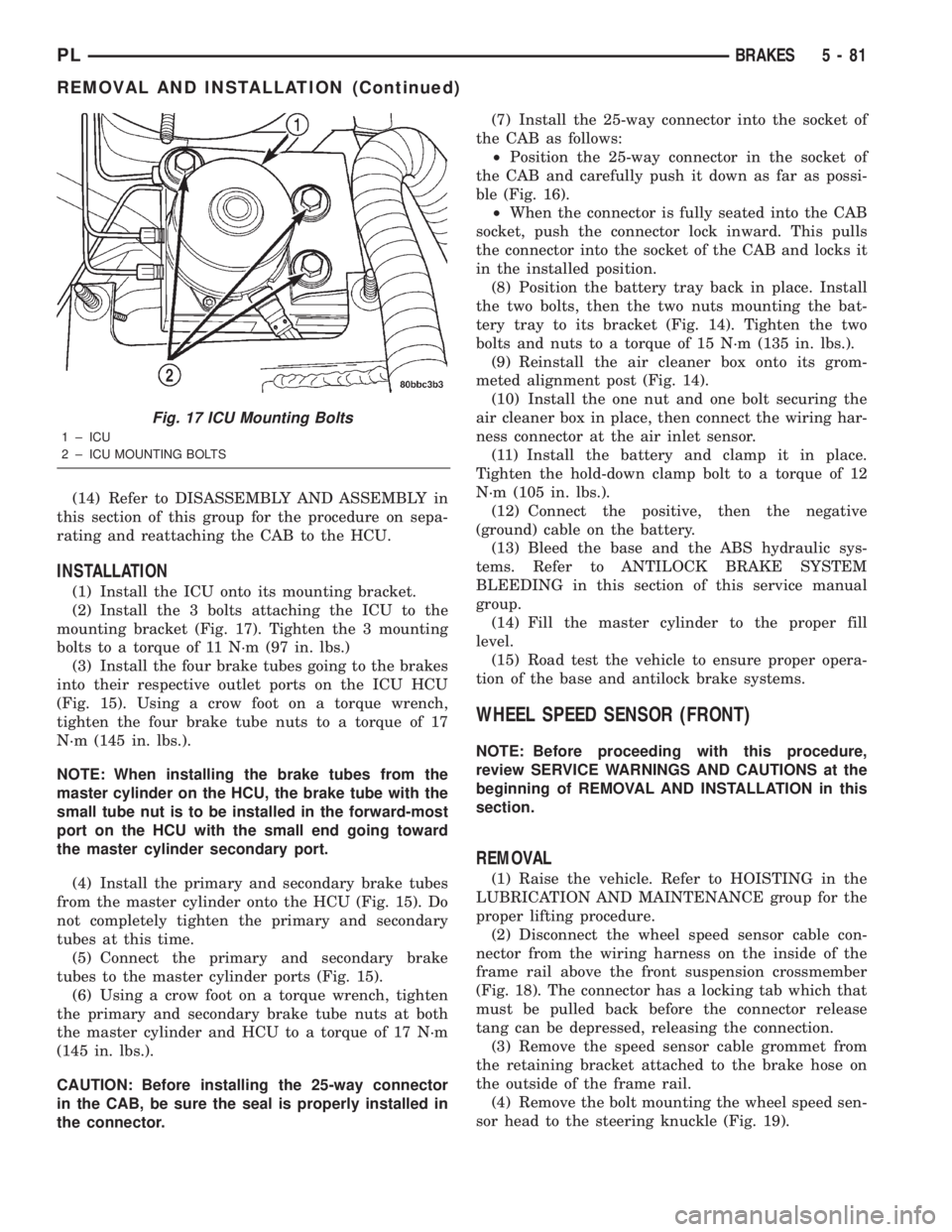
(2) Install the 3 bolts attaching the ICU to the
mounting bracket (Fig. 17). Tighten the 3 mounting
bolts to a torque of 11 N´m (97 in. lbs.)
(3) Install the four brake tubes going to the brakes
into their respective outlet ports on the ICU HCU
(Fig. 15). Using a crow foot on a torque wrench,
tighten the four brake tube nuts to a torque of 17
N´m (145 in. lbs.).
NOTE: When installing the brake tubes from the
master cylinder on the HCU, the brake tube with the
small tube nut is to be installed in the forward-most
port on the HCU with the small end going toward
the master cylinder secondary port.
(4) Install the primary and secondary brake tubes
from the master cylinder onto the HCU (Fig. 15). Do
not completely tighten the primary and secondary
tubes at this time.
(5) Connect the primary and secondary brake
tubes to the master cylinder ports (Fig. 15).
(6) Using a crow foot on a torque wrench, tighten
the primary and secondary brake tube nuts at both
the master cylinder and HCU to a torque of 17 N´m
(145 in. lbs.).
CAUTION: Before installing the 25-way connector
in the CAB, be sure the seal is properly installed in
the connector.(7) Install the 25-way connector into the socket of
the CAB as follows:
²Position the 25-way connector in the socket of
the CAB and carefully push it down as far as possi-
ble (Fig. 16).
²When the connector is fully seated into the CAB
socket, push the connector lock inward. This pulls
the connector into the socket of the CAB and locks it
in the installed position.
(8) Position the battery tray back in place. Install
the two bolts, then the two nuts mounting the bat-
tery tray to its bracket (Fig. 14). Tighten the two
bolts and nuts to a torque of 15 N´m (135 in. lbs.).
(9) Reinstall the air cleaner box onto its grom-
meted alignment post (Fig. 14).
(10) Install the one nut and one bolt securing the
air cleaner box in place, then connect the wiring har-
ness connector at the air inlet sensor.
(11) Install the battery and clamp it in place.
Tighten the hold-down clamp bolt to a torque of 12
N´m (105 in. lbs.).
(12) Connect the positive, then the negative
(ground) cable on the battery.
(13) Bleed the base and the ABS hydraulic sys-
tems. Refer to ANTILOCK BRAKE SYSTEM
BLEEDING in this section of this service manual
group.
(14) Fill the master cylinder to the proper fill
level.
(15) Road test the vehicle to ensure proper opera-
tion of the base and antilock brake systems.
WHEEL SPEED SENSOR (FRONT)
NOTE: Before proceeding with this procedure,
review SERVICE WARNINGS AND CAUTIONS at the
beginning of REMOVAL AND INSTALLATION in this
section.
REMOVAL
(1) Raise the vehicle. Refer to HOISTING in the
LUBRICATION AND MAINTENANCE group for the
proper lifting procedure.
(2) Disconnect the wheel speed sensor cable con-
nector from the wiring harness on the inside of the
frame rail above the front suspension crossmember
(Fig. 18). The connector has a locking tab which that
must be pulled back before the connector release
tang can be depressed, releasing the connection.
(3) Remove the speed sensor cable grommet from
the retaining bracket attached to the brake hose on
the outside of the frame rail.
(4) Remove the bolt mounting the wheel speed sen-
sor head to the steering knuckle (Fig. 19).
Fig. 17 ICU Mounting Bolts
1 ± ICU
2 ± ICU MOUNTING BOLTS
PLBRAKES 5 - 81
REMOVAL AND INSTALLATION (Continued)
Page 168 of 1285
SERVICE DIAGNOSISÐCLUTCH GRAB/CHATTER
CONDITION POSSIBLE CAUSES CORRECTION
CLUTCH DISC
FACING COVERED
WITH OIL OR
GREASEOil leak at engine rear main or transaxle
input shaft sealCorrect leak and replace modular clutch
assembly
Too much grease applied to splines of disc
and input shaftApply lighter coating of grease to splines
NO FAULT FOUND
WITH CLUTCH
COMPONENTSProblem actually related to suspension or
driveline componentFurther diagnosis required. Check
engine/transmission mounts, suspension
attaching parts and other driveline
components as needed.
Engine related problems Check EFI and ignition systems
PARTIAL
ENGAGEMENT OF
CLUTCH DISCClutch cover, spring, or release fingers
bent, distorted (rough handling, improper
assembly)Replace modular clutch assembly
Clutch disc damaged or distorted Replace modular clutch assembly
Clutch misalignment Check alignment and runout of flywheel,
disc, or cover. Check clutch housing to
engine dowels and dowel holes for damage.
Correct as necessary.
SERVICE DIAGNOSISÐCLUTCH SLIPS
CONDITION POSSIBLE CAUSES CORRECTION
DISC FACING
WORN OUTNormal wear. Replace modular clutch assembly.
Driver frequently rides (slips) clutch, results
in rapid wear overheating.Replace modular clutch assembly
Insufficient clutch cover diaphragm spring
tensionReplace modular clutch assembly
CLUTCH DISC
FACING
CONTAMINATED
WITH OIL OR
GREASELeak at rear main oil seal or transaxle input
shaft sealReplace leaking seals. Replace modular
clutch assembly.
Excessive amount of grease applied to
input shaft splinesApply less grease to input shaft. Replace
modular clutch assembly
Road splash, water entering housing Seal housing. Inspect clutch assembly.
CLUTCH IS
RUNNING
PARTIALLY
DISENGAGEDRelease bearing sticking or binding, does
not return to normal running position.Verify that bearing is actually binding. Then,
replace bearing and transmission front
bearing retainer if sleeve surface is
damaged.
Cable self-adjuster mechanism sticking or
binding causing high preloadVerify that self-adjuster is free to move
PLCLUTCH 6 - 3
DIAGNOSIS AND TESTING (Continued)
Page 311 of 1285
HEADLAMP ALIGNMENT
TABLE OF CONTENTS
page page
DESCRIPTION AND OPERATION
HEADLAMP ALIGNMENT....................4
SERVICE PROCEDURES
HEADLAMP ALIGNMENT PREPARATION........4ADJUSTMENTS
HEADLAMP ADJUSTMENT USING
ALIGNMENT SCREEN....................4
FOG LAMP ALIGNMENT....................6
DESCRIPTION AND OPERATION
HEADLAMP ALIGNMENT
Headlamps and Fog Lamps should be aligned
using the screen method which is provided in this
section.The preferred headlamp alignment set-
ting is 0 for the left/right adjustment and 0 for
the up/down adjustment.
SERVICE PROCEDURES
HEADLAMP ALIGNMENT PREPARATION
(1) Verify headlamp dimmer switch and high beam
indicator operation.
(2) Inspect and correct damaged or defective com-
ponents that could interfere with proper headlamp
alignment.
(3) Verify proper tire inflation.
(4) Clean headlamp lenses.
(5) Verify that luggage area is not heavily loaded.
(6) Fuel tank should be FULL. Add 2.94 kg (6.5
lbs.) of weight over the fuel tank for each estimated
gallon of missing fuel.
ADJUSTMENTS
HEADLAMP ADJUSTMENT USING ALIGNMENT
SCREEN
ALIGNMENT SCREEN PREPARATION
(1) Position vehicle on a level surface perpendicu-
lar to a flat wall 7.62 meters (25 ft.) away from front
of headlamp lens.
(2) If necessary, tape a line on the floor 7.62
meters (25 ft.) away from and parallel to the wall
(Fig. 1).(3) From the floor up 1.27 meters (5 ft.), tape a
line on the wall at the center line of the vehicle.
Sight along the center line of the vehicle (from rear
of vehicle forward) to verify accuracy of the line
placement.
(4) Rock vehicle side-to-side three times to allow
suspension to stabilize.
(5) Jounce front suspension three times by pushing
downward on front bumper and releasing.
(6) A small dot is molded into each headlamp lens
signifying the center of the headlamp. Measure the
distance from the center of the headlamp to the floor.
Transfer measurement to the alignment screen (with
tape). Use this line for up/down adjustment refer-
ence.
(7) Measure distance from the center line of the
vehicle to the center of each headlamp being aligned.
Transfer measurements to screen (with tape) to each
side of vehicle center line. Use these lines for left/
right adjustment reference.
HEADLAMP ADJUSTMENT
The PL headlamp low beam pattern has a distinct
horizontal cutoff line which is used to visually align
the headlamps. A properly aimed headlamp will have
the horizontal cutoff line of the low beam pattern
centered on the low beam pattern centered on the
horizontal center of headlamp line. The side to side
left edge of the low beam hot spot should be located
75 mm (3 inches) to the left of the headlamp center
line (Fig. 1). The high beams on a vehicle with aero
headlamps cannot be aligned. The high beam pattern
should be correct when the low beams are aligned
properly.
To adjust headlamp alignment, rotate alignment
screws to achieve the specified low beam hot spot
pattern.
8L - 4 LAMPSPL
Page 397 of 1285
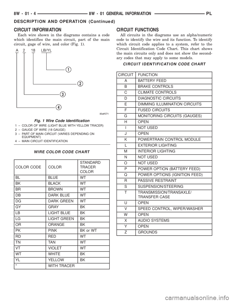
CIRCUIT INFORMATION
Each wire shown in the diagrams contains a code
which identifies the main circuit, part of the main
circuit, gage of wire, and color (Fig. 1).
CIRCUIT FUNCTIONS
All circuits in the diagrams use an alpha/numeric
code to identify the wire and its function. To identify
which circuit code applies to a system, refer to the
Circuit Identification Code Chart. This chart shows
the main circuits only and does not show the second-
ary codes that may apply to some models.
Fig. 1 Wire Code Identification
1 ± COLOR OF WIRE (LIGHT BLUE WITH YELLOW TRACER)
2 ± GAUGE OF WIRE (18 GAUGE)
3 ± PART OF MAIN CIRCUIT (VARIES DEPENDING ON
EQUIPMENT)
4 ± MAIN CIRCUIT IDENTIFICATION
WIRE COLOR CODE CHART
COLOR CODE COLORSTANDARD
TRACER
COLOR
BL BLUE WT
BK BLACK WT
BR BROWN WT
DB DARK BLUE WT
DG DARK GREEN WT
GY GRAY BK
LB LIGHT BLUE BK
LG LIGHT GREEN BK
OR ORANGE BK
PK PINK BK or WT
RD RED WT
TN TAN WT
VT VIOLET WT
WT WHITE BK
YL YELLOW BK
* WITH TRACER
CIRCUIT IDENTIFICATION CODE CHART
CIRCUIT FUNCTION
A BATTERY FEED
B BRAKE CONTROLS
C CLIMATE CONTROLS
D DIAGNOSTIC CIRCUITS
E DIMMING ILLUMINATION CIRCUITS
F FUSED CIRCUITS
G MONITORING CIRCUITS (GAUGES)
H OPEN
I NOT USED
J OPEN
K POWERTRAIN CONTROL MODULE
L EXTERIOR LIGHTING
M INTERIOR LIGHTING
N NOT USED
O NOT USED
P POWER OPTION (BATTERY FEED)
Q POWER OPTIONS (IGNITION FEED)
R PASSIVE RESTRAINT
S SUSPENSION/STEERING
T TRANSMISSION/TRANSAXLE/
TRANSFER CASE
U OPEN
V SPEED CONTROL, WIPER/WASHER
W OPEN
X AUDIO SYSTEMS
Y OPEN
Z GROUNDS
8W - 01 - 4 8W - 01 GENERAL INFORMATIONPL
DESCRIPTION AND OPERATION (Continued)
Page 743 of 1285
CRANKSHAFT END PLAY
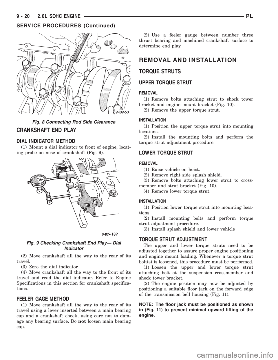
DIAL INDICATOR METHOD
(1) Mount a dial indicator to front of engine, locat-
ing probe on nose of crankshaft (Fig. 9).
(2) Move crankshaft all the way to the rear of its
travel.
(3) Zero the dial indicator.
(4) Move crankshaft all the way to the front of its
travel and read the dial indicator. Refer to Engine
Specifications in this section for crankshaft specifica-
tions.
FEELER GAGE METHOD
(1) Move crankshaft all the way to the rear of its
travel using a lever inserted between a main bearing
cap and a crankshaft cheek, using care not to dam-
age any bearing surface. Donotloosen main bearing
cap.(2) Use a feeler gauge between number three
thrust bearing and machined crankshaft surface to
determine end play.
REMOVAL AND INSTALLATION
TORQUE STRUTS
UPPER TORQUE STRUT
REMOVAL
(1) Remove bolts attaching strut to shock tower
bracket and engine mount bracket (Fig. 10).
(2) Remove the upper torque strut.
INSTALLATION
(1) Position the upper torque strut into mounting
locations.
(2) Install the mounting bolts and perform the
torque strut adjustment procedure.
LOWER TORQUE STRUT
REMOVAL
(1) Raise vehicle on hoist.
(2) Remove right side splash shield.
(3) Remove bolts attaching lower strut to cross-
member and strut bracket (Fig. 10).
(4) Remove lower torque strut.
INSTALLATION
(1) Position lower torque strut into mounting loca-
tions.
(2) Install mounting bolts and perform torque
strut adjustment procedure.
(3) Install splash shield and lower vehicle
TORQUE STRUT ADJUSTMENT
The upper and lower torque struts need to be
adjusted together to assure proper engine positioning
and engine mount loading. Whenever a torque strut
bolt(s) is loosened, this procedure must be performed.
(1) Loosen the upper and lower torque strut
attaching bolt at the suspension crossmember and
shock tower bracket.
(2) The engine position may now be adjusted by
positioning a suitable floor jack on the forward edge
of the transmission bell housing (Fig. 11).
NOTE: The floor jack must be positioned as shown
in (Fig. 11) to prevent minimal upward lifting of the
engine.
Fig. 8 Connecting Rod Side Clearance
Fig. 9 Checking Crankshaft End PlayÐ Dial
Indicator
9 - 20 2.0L SOHC ENGINEPL
SERVICE PROCEDURES (Continued)
Page 789 of 1285
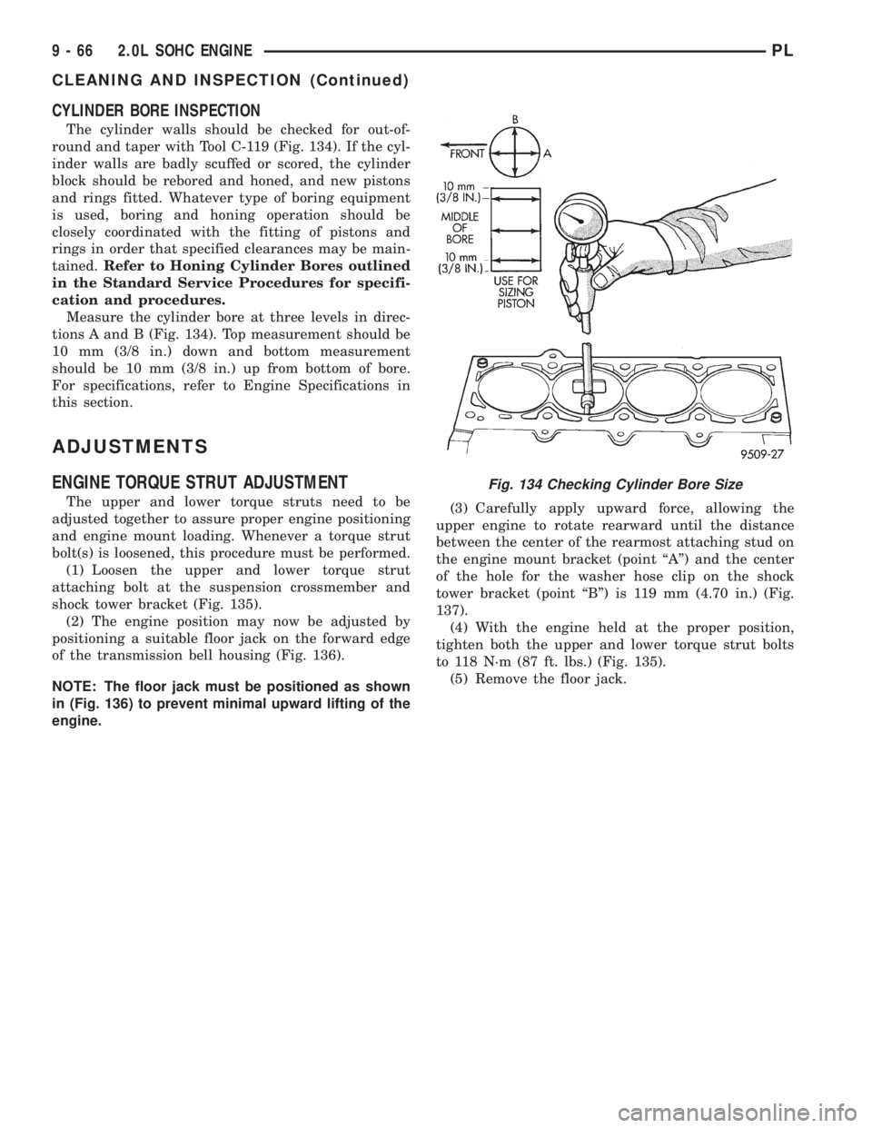
CYLINDER BORE INSPECTION
The cylinder walls should be checked for out-of-
round and taper with Tool C-119 (Fig. 134). If the cyl-
inder walls are badly scuffed or scored, the cylinder
block should be rebored and honed, and new pistons
and rings fitted. Whatever type of boring equipment
is used, boring and honing operation should be
closely coordinated with the fitting of pistons and
rings in order that specified clearances may be main-
tained.Refer to Honing Cylinder Bores outlined
in the Standard Service Procedures for specifi-
cation and procedures.
Measure the cylinder bore at three levels in direc-
tions A and B (Fig. 134). Top measurement should be
10 mm (3/8 in.) down and bottom measurement
should be 10 mm (3/8 in.) up from bottom of bore.
For specifications, refer to Engine Specifications in
this section.
ADJUSTMENTS
ENGINE TORQUE STRUT ADJUSTMENT
The upper and lower torque struts need to be
adjusted together to assure proper engine positioning
and engine mount loading. Whenever a torque strut
bolt(s) is loosened, this procedure must be performed.
(1) Loosen the upper and lower torque strut
attaching bolt at the suspension crossmember and
shock tower bracket (Fig. 135).
(2) The engine position may now be adjusted by
positioning a suitable floor jack on the forward edge
of the transmission bell housing (Fig. 136).
NOTE: The floor jack must be positioned as shown
in (Fig. 136) to prevent minimal upward lifting of the
engine.(3) Carefully apply upward force, allowing the
upper engine to rotate rearward until the distance
between the center of the rearmost attaching stud on
the engine mount bracket (point ªAº) and the center
of the hole for the washer hose clip on the shock
tower bracket (point ªBº) is 119 mm (4.70 in.) (Fig.
137).
(4) With the engine held at the proper position,
tighten both the upper and lower torque strut bolts
to 118 N´m (87 ft. lbs.) (Fig. 135).
(5) Remove the floor jack.
Fig. 134 Checking Cylinder Bore Size
9 - 66 2.0L SOHC ENGINEPL
CLEANING AND INSPECTION (Continued)
Page 804 of 1285
CATALYTIC CONVERTER
REMOVAL
WARNING: THE NORMAL OPERATING TEMPERA-
TURE OF THE EXHAUST SYSTEM IS VERY HIGH.
THEREFORE, NEVER ATTEMPT TO SERVICE ANY
PART OF THE EXHAUST SYSTEM UNTIL IT IS
COOLED. SPECIAL CARE SHOULD BE TAKEN
WHEN WORKING NEAR THE CATALYTIC CON-
VERTER. THE TEMPERATURE OF THE CONVERTER
RISES TO A HIGH LEVEL AFTER A SHORT PERIOD
OF ENGINE OPERATION TIME.
NOTE: Vehicles equipped with the ULEV emission
package are equipped with an additional catalytic
converter that is integral to the exhaust manifold.
Refer to Exhaust Manifold in Group 9, Engine for
procedure.
(1) Remove muffler and exhaust pipe. Refer to pro-
cedure in this section.
(2) Disconnect downstream oxygen sensor electri-
cal connector.
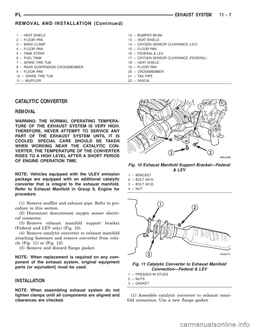
(3) Remove exhaust manifold support bracket
(Federal and LEV only) (Fig. 10).
(4) Remove catalytic converter to exhaust manifold
attaching fasteners and remove converter from vehi-
cle (Fig. 11) or (Fig. 12).
(5) Remove and discard flange gasket.
NOTE: When replacement is required on any com-
ponent of the exhaust system, original equipment
parts (or equivalent) must be used.
INSTALLATION
NOTE: When assembling exhaust system do not
tighten clamps until all components are aligned and
clearances are checked.(1) Assemble catalytic converter to exhaust mani-
fold connection. Use a new flange gasket.
1 ± HEAT SHIELD
2 ± FLOOR PAN
3 ± BAND CLAMP
4 ± FLOOR PAN
5 ± TANK STRAP
6 ± FUEL TANK
7 ± SPARE TIRE TUB
8 ± REAR SUSPENSION CROSSMEMBER
9 ± FLOOR PAN
10 ± SPARE TIRE TUB
11 ± MUFFLER12 ± BUMPER BEAM
13 ± HEAT SHIELD
14 ± OXYGEN SENSOR CLEARANCE (LEV)
15 ± FLOOR PAN
16 ± FEDERAL & LEV
17 ± OXYGEN SENSOR CLEARANCE (FEDERAL)
18 ± HEAT SHIELD
19 ± FLOOR PAN
20 ± CROSSMEMBER
21 ± TAIL PIPE
22 ± FASCIA
Fig. 10 Exhaust Manifold Support BracketÐFederal
& LEV
1 ± BRACKET
2 ± BOLT (M10)
3 ± BOLT (M12)
4 ± NUT
Fig. 11 Catalytic Converter to Exhaust Manifold
ConnectionÐFederal & LEV
1 ± PRESSED-IN STUDS
2 ± NUTS
3 ± GASKET
PLEXHAUST SYSTEM 11 - 7
REMOVAL AND INSTALLATION (Continued)