2000 DODGE NEON suspension
[x] Cancel search: suspensionPage 45 of 1285
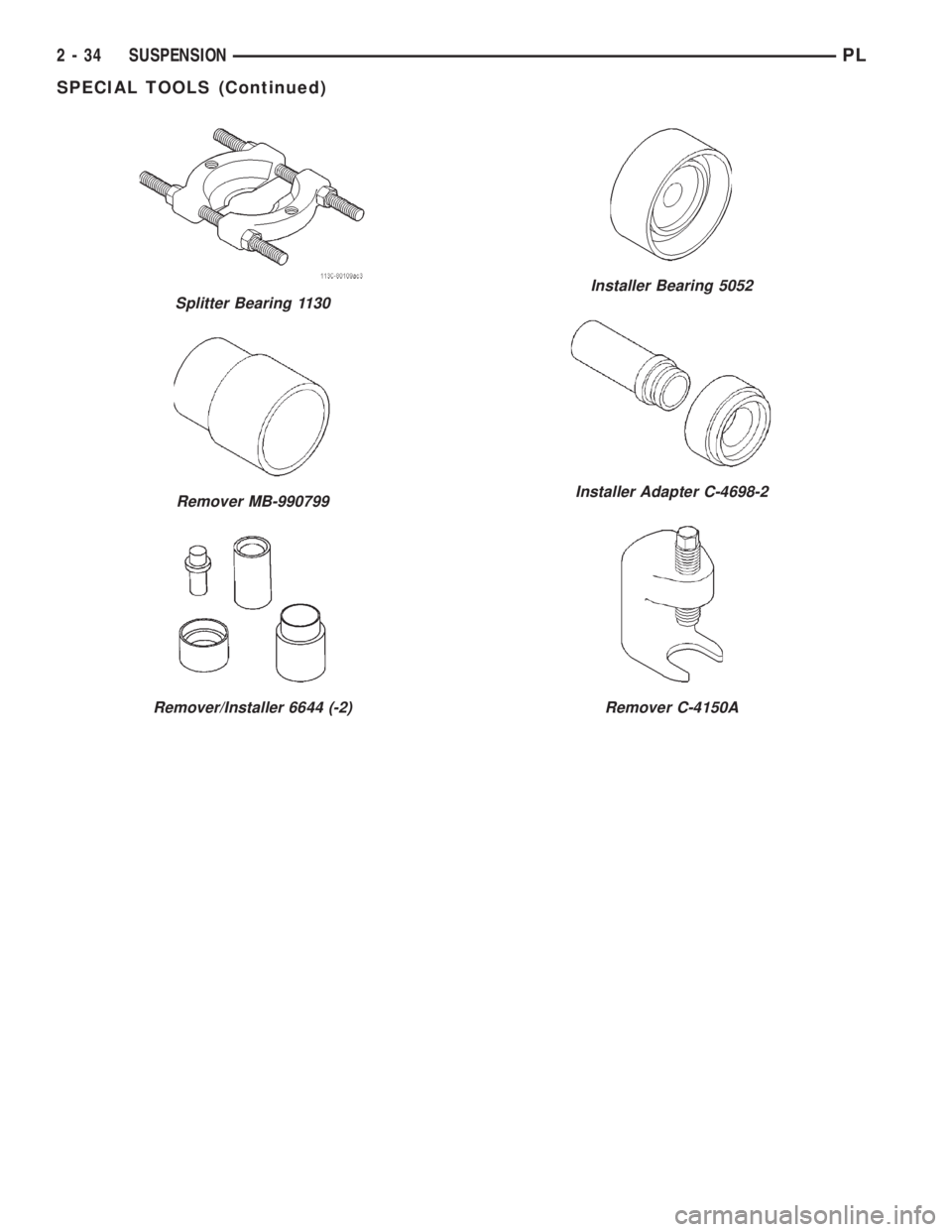
Splitter Bearing 1130
Remover MB-990799
Remover/Installer 6644 (-2)
Installer Bearing 5052
Installer Adapter C-4698-2
Remover C-4150A
2 - 34 SUSPENSIONPL
SPECIAL TOOLS (Continued)
Page 46 of 1285
REAR SUSPENSION
TABLE OF CONTENTS
page page
DESCRIPTION AND OPERATION
REAR SUSPENSION SYSTEM.............35
STRUT ASSEMBLY (REAR)................37
KNUCKLE (REAR).......................37
HUB AND BEARING (REAR)...............37
LATERAL ARMS........................37
TENSION STRUT.......................38
STABILIZER BAR (REAR).................38
DIAGNOSIS AND TESTING
STRUT ASSEMBLY (REAR)................38
KNUCKLE (REAR).......................39
HUB AND BEARING (REAR)...............39
LATERAL ARMS........................39
TENSION STRUT.......................39
STABILIZER BAR (REAR).................39REMOVAL AND INSTALLATION
SERVICE WARNINGS AND CAUTIONS........40
STRUT ASSEMBLY (REAR).................40
KNUCKLE (REAR)........................42
HUB AND BEARING (REAR)................44
LATERAL ARMS..........................45
TENSION STRUT.........................46
STABILIZER BAR (REAR)...................47
DISASSEMBLY AND ASSEMBLY
STRUT ASSEMBLY (REAR).................47
SPECIFICATIONS
REAR SUSPENSION FASTENER TORQUE
SPECIFICATIONS........................50
SPECIAL TOOLS
REAR SUSPENSION......................50
DESCRIPTION AND OPERATION
REAR SUSPENSION SYSTEM
The rear suspension system used on this vehicle is
a fully independent type rear suspension system (Fig.
1). This means that each side of the rear suspension
acts independently from the other.
The rear suspension is supported by a strut assem-
bly. The strut assembly also controls ride quality.When the vehicle strikes a bump, the force is trans-
ferred through the hub, bearing, and knuckle, into
the strut assembly to absorb the force and dampen it.
Lateral movement of the rear knuckle is controlled
by lateral arms going from the front and rear of the
knuckle to the rear crossmember. Fore and aft move-
ment of the knuckle is controlled by a tension strut.
PLSUSPENSION 2 - 35
Page 47 of 1285
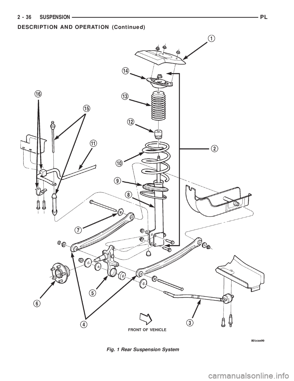
Fig. 1 Rear Suspension System
2 - 36 SUSPENSIONPL
DESCRIPTION AND OPERATION (Continued)
Page 48 of 1285
For more information on the description and oper-
ation of an individual component, refer to the appli-
cable component heading in this section.
STRUT ASSEMBLY (REAR)
The rear strut assemblies support the weight of
the vehicle using coil springs positioned around
struts. The coil springs are contained between the
upper mount of the strut assembly and a lower
spring seat on the body of the strut.
The top of each strut assembly is bolted to the top
of the inner fender through a rubber isolated mount.
The bottom of the strut assembly attaches to the rear
knuckle using 2 thru-bolts with prevailing torque
nuts.
The rear strut assembly includes the following
components (Fig. 1): A rubber isolated upper mount,
a dust shield, a jounce bumper, a coil spring, a lower
spring isolator, and a strut. Any component in need
of service requires removal of the strut assembly
from the vehicle and disassembly of it.
COIL SPRING
Rear coil springs are rated separately for each cor-
ner or side of the vehicle depending on optional
equipment and type of vehicle service. If a coil spring
requires replacement, be sure the spring needing
replacement is replaced with a spring meeting the
correct load rating for the vehicle with its specific
options.
KNUCKLE (REAR)
A forged rear knuckle bolts to each rear strut
assembly (Fig. 1). The rear knuckle's spindle sup-
ports the rear hub and bearing. Together they sup-
port the rear tire and wheel. The movement of the
rear knuckle is controlled laterally using two lateral
arms attached to the knuckle. Fore and aft move-
ment of the knuckle is controlled by using a tension
strut.
HUB AND BEARING (REAR)
The hub and bearing is mounted on the rear
knuckle's spindle (Fig. 1). The hub and bearing
adapts the tire and wheel assembly to the knuckle.
It's bearing allows the tire and wheel assembly to
rotate freely on the vehicle.
All vehicles are equipped with permanently lubri-
cated and sealed for life rear wheel bearings. There
is no periodic lubrication or maintenance recom-
mended for these units.
The only servicable components of the hub and
bearing are the wheel mounting studs.
If a vehicle is equipped with antilock brakes, the
tone wheels for the rear wheel speed sensors are
pressed onto the hub.
LATERAL ARMS
The lateral arms control the lateral movement of
the rear suspension, specifically the knuckle (Fig. 1).
There are two lateral arms per side of the rear sus-
pension. One arm is attached to the front end of the
knuckle and the other is attached to the rear of the
knuckle. The other end of each lateral arm attaches
to the rear crossmember.
Visually it appears that the left rear arm is
mounted backwards in relation to the other arms
(Fig. 2). Although the left rear arm looks like it is
same as the right rear arm, just reversed, it is not
the same; the arms are not interchangeable.
The front arms are interchangeable, but should be
mounted with the side displaying the word ªFOR-
WARDº stamped into it toward the front of the vehi-
cle. The trimmed outer edge of the arms will then be
facing the rear of the vehicle.
1 ± VEHICLE STRUT TOWER
2 ± STRUT ASSEMBLY
3 ± TENSION STRUT
4 ± LATERAL ARMS
5 ± KNUCKLE
6 ± HUB AND BEARING
7 ± WHEEL ALIGNMENT ADJUSTMENT CAM
8 ± STRUT9 ± LOWER SPRING ISOLATOR
10 ± COIL SPRING
11 ± STABILIZER BAR
12 ± JOUNCE BUMPER
13 ± DUST SHIELD
14 ± UPPER MOUNT
15 ± STABILIZER BAR LINK
16 ± STABILIZER BAR CUSHION AND RETAINER
PLSUSPENSION 2 - 37
DESCRIPTION AND OPERATION (Continued)
Page 49 of 1285
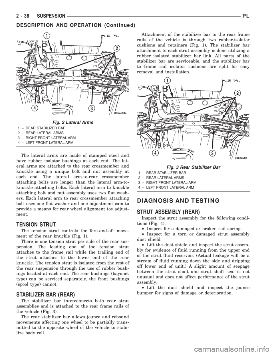
The lateral arms are made of stamped steel and
have rubber isolator bushings at each end. The lat-
eral arms are attached to the rear crossmember and
knuckle using a unique bolt and nut assembly at
each end. The lateral arm-to-rear crossmember
attaching bolts are longer than the lateral arm-to-
knuckle attaching bolts. Each lateral arm to knuckle
attaching bolt and nut assembly uses two flat wash-
ers. Each lateral arm to rear crossmember attaching
bolt uses one flat washer and one adjustment cam to
provide a means for rear wheel alignment toe adjust-
ment.
TENSION STRUT
The tension strut controls the fore-and-aft move-
ment of the rear knuckle (Fig. 1).
There is one tension strut per side of the rear sus-
pension. The leading end of the tension strut
attaches to the frame rail while the trailing end of
the strut attaches to the lower end of the rear
knuckle. The tension strut is isolated from the rest of
the rear suspension through the use of rubber bush-
ings located at each end. The rear bushings (bayonet
type) can be serviced separately, the front bushings
(spool type) cannot.
STABILIZER BAR (REAR)
The stabilizer bar interconnects both rear strut
assemblies and is attached to the rear frame rails of
the vehicle (Fig. 3).
The rear stabilizer bar allows jounce and rebound
movements affecting one wheel to be partially trans-
mitted to the opposite wheel of the vehicle to stabi-
lize body roll.Attachment of the stabilizer bar to the rear frame
rails of the vehicle is through two rubber-isolator
cushions and retainers (Fig. 1). The stabilizer bar
attachment to each strut assembly is done utilizing a
rubber isolated stabilizer bar link. All parts of the
stabilizer bar are serviceable, and the stabilizer bar
to frame rail isolator cushions are split for easy
removal and installation.
DIAGNOSIS AND TESTING
STRUT ASSEMBLY (REAR)
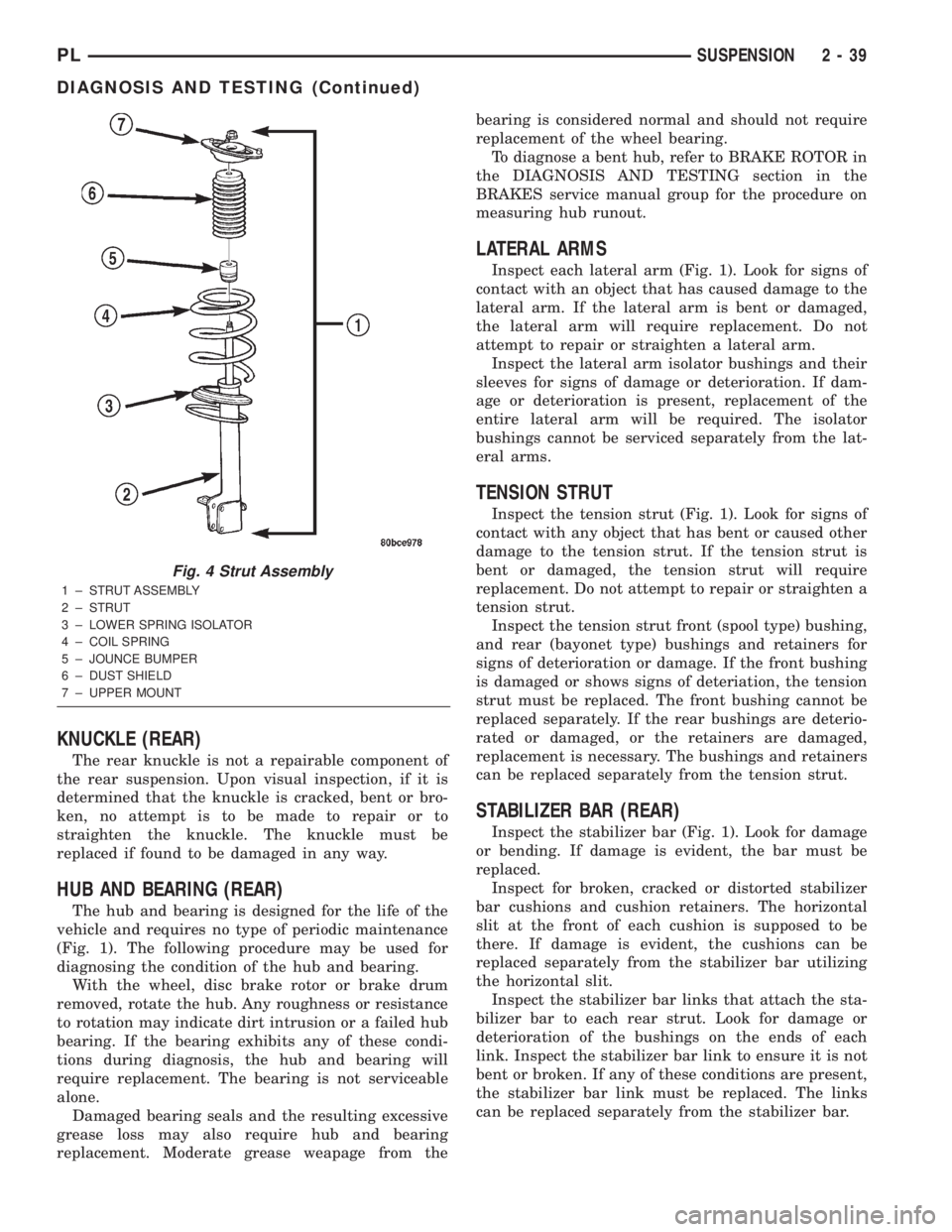
Inspect the strut assembly for the following condi-
tions (Fig. 4):
²Inspect for a damaged or broken coil spring.
²Inspect for a torn or damaged strut assembly
dust shield.
²Lift the dust shield and inspect the strut assem-
bly for evidence of fluid running from the upper end
of the strut fluid reservoir. (Actual leakage will be a
stream of fluid running down the side and dripping
off lower end of unit.) A slight amount of seepage
between the strut shaft and strut shaft seal is not
unusual and does not affect performance of the strut
assembly.
²Lift the dust shield and inspect the jounce
bumper for signs of damage or deterioration.
Fig. 2 Lateral Arms
1 ± REAR STABILIZER BAR
2 ± REAR LATERAL ARMS
3 ± RIGHT FRONT LATERAL ARM
4 ± LEFT FRONT LATERAL ARM
Fig. 3 Rear Stabilizer Bar
1 ± REAR STABILIZER BAR
2 ± REAR LATERAL ARMS
3 ± RIGHT FRONT LATERAL ARM
4 ± LEFT FRONT LATERAL ARM
2 - 38 SUSPENSIONPL
DESCRIPTION AND OPERATION (Continued)
Page 50 of 1285
KNUCKLE (REAR)
The rear knuckle is not a repairable component of
the rear suspension. Upon visual inspection, if it is
determined that the knuckle is cracked, bent or bro-
ken, no attempt is to be made to repair or to
straighten the knuckle. The knuckle must be
replaced if found to be damaged in any way.
HUB AND BEARING (REAR)
The hub and bearing is designed for the life of the
vehicle and requires no type of periodic maintenance
(Fig. 1). The following procedure may be used for
diagnosing the condition of the hub and bearing.
With the wheel, disc brake rotor or brake drum
removed, rotate the hub. Any roughness or resistance
to rotation may indicate dirt intrusion or a failed hub
bearing. If the bearing exhibits any of these condi-
tions during diagnosis, the hub and bearing will
require replacement. The bearing is not serviceable
alone.
Damaged bearing seals and the resulting excessive
grease loss may also require hub and bearing
replacement. Moderate grease weapage from thebearing is considered normal and should not require
replacement of the wheel bearing.
To diagnose a bent hub, refer to BRAKE ROTOR in
the DIAGNOSIS AND TESTING section in the
BRAKES service manual group for the procedure on
measuring hub runout.
LATERAL ARMS
Inspect each lateral arm (Fig. 1). Look for signs of
contact with an object that has caused damage to the
lateral arm. If the lateral arm is bent or damaged,
the lateral arm will require replacement. Do not
attempt to repair or straighten a lateral arm.
Inspect the lateral arm isolator bushings and their
sleeves for signs of damage or deterioration. If dam-
age or deterioration is present, replacement of the
entire lateral arm will be required. The isolator
bushings cannot be serviced separately from the lat-
eral arms.
TENSION STRUT
Inspect the tension strut (Fig. 1). Look for signs of
contact with any object that has bent or caused other
damage to the tension strut. If the tension strut is
bent or damaged, the tension strut will require
replacement. Do not attempt to repair or straighten a
tension strut.
Inspect the tension strut front (spool type) bushing,
and rear (bayonet type) bushings and retainers for
signs of deterioration or damage. If the front bushing
is damaged or shows signs of deteriation, the tension
strut must be replaced. The front bushing cannot be
replaced separately. If the rear bushings are deterio-
rated or damaged, or the retainers are damaged,
replacement is necessary. The bushings and retainers
can be replaced separately from the tension strut.
STABILIZER BAR (REAR)
Inspect the stabilizer bar (Fig. 1). Look for damage
or bending. If damage is evident, the bar must be
replaced.
Inspect for broken, cracked or distorted stabilizer
bar cushions and cushion retainers. The horizontal
slit at the front of each cushion is supposed to be
there. If damage is evident, the cushions can be
replaced separately from the stabilizer bar utilizing
the horizontal slit.
Inspect the stabilizer bar links that attach the sta-
bilizer bar to each rear strut. Look for damage or
deterioration of the bushings on the ends of each
link. Inspect the stabilizer bar link to ensure it is not
bent or broken. If any of these conditions are present,
the stabilizer bar link must be replaced. The links
can be replaced separately from the stabilizer bar.
Fig. 4 Strut Assembly
1 ± STRUT ASSEMBLY
2 ± STRUT
3 ± LOWER SPRING ISOLATOR
4 ± COIL SPRING
5 ± JOUNCE BUMPER
6 ± DUST SHIELD
7 ± UPPER MOUNT
PLSUSPENSION 2 - 39
DIAGNOSIS AND TESTING (Continued)
Page 51 of 1285
REMOVAL AND INSTALLATION
SERVICE WARNINGS AND CAUTIONS
WARNING: DO NOT REMOVE THE STRUT SHAFT
NUT WHILE STRUT ASSEMBLY IS INSTALLED IN
VEHICLE, OR BEFORE THE COIL SPRING IS COM-
PRESSED WITH A COMPRESSION TOOL. THE
SPRING IS HELD UNDER HIGH PRESSURE.
CAUTION: Only frame contact or wheel lift hoisting
equipment can be used on vehicles having a fully
independent rear suspension. Vehicles with inde-
pendent rear suspension can not be hoisted using
equipment designed to lift a vehicle by the rear
axle. If this type of hoisting equipment is used dam-
age to rear suspension components will occur.
NOTE: If a rear suspension component becomes
bent, damaged or fails, no attempt should be made
to straighten or repair it. Always replace it with a
new component.
STRUT ASSEMBLY (REAR)
NOTE: Before proceeding with this procedure,
review SERVICE WARNINGS AND CAUTIONS at the
beginning of REMOVAL AND INSTALLATION in this
section.
REMOVAL
(1) Raise the vehicle. Refer to HOISTING in the
LUBRICATION AND MAINTENANCE group for the
proper lifting procedure.
(2) Remove the rear wheel and tire assembly from
the vehicle.
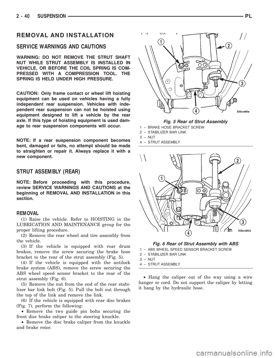
(3) If the vehicle is equipped with rear drum
brakes, remove the screw securing the brake hose
bracket to the rear of the strut assembly (Fig. 5).
(4) If the vehicle is equipped with the antilock
brake system (ABS), remove the screw securing the
ABS wheel speed sensor bracket to the rear of the
strut assembly (Fig. 6).
(5) Remove the nut from the end of the rear stabi-
lizer bar link bolt (Fig. 5). Pull the bolt out through
the top of the link and remove the link.
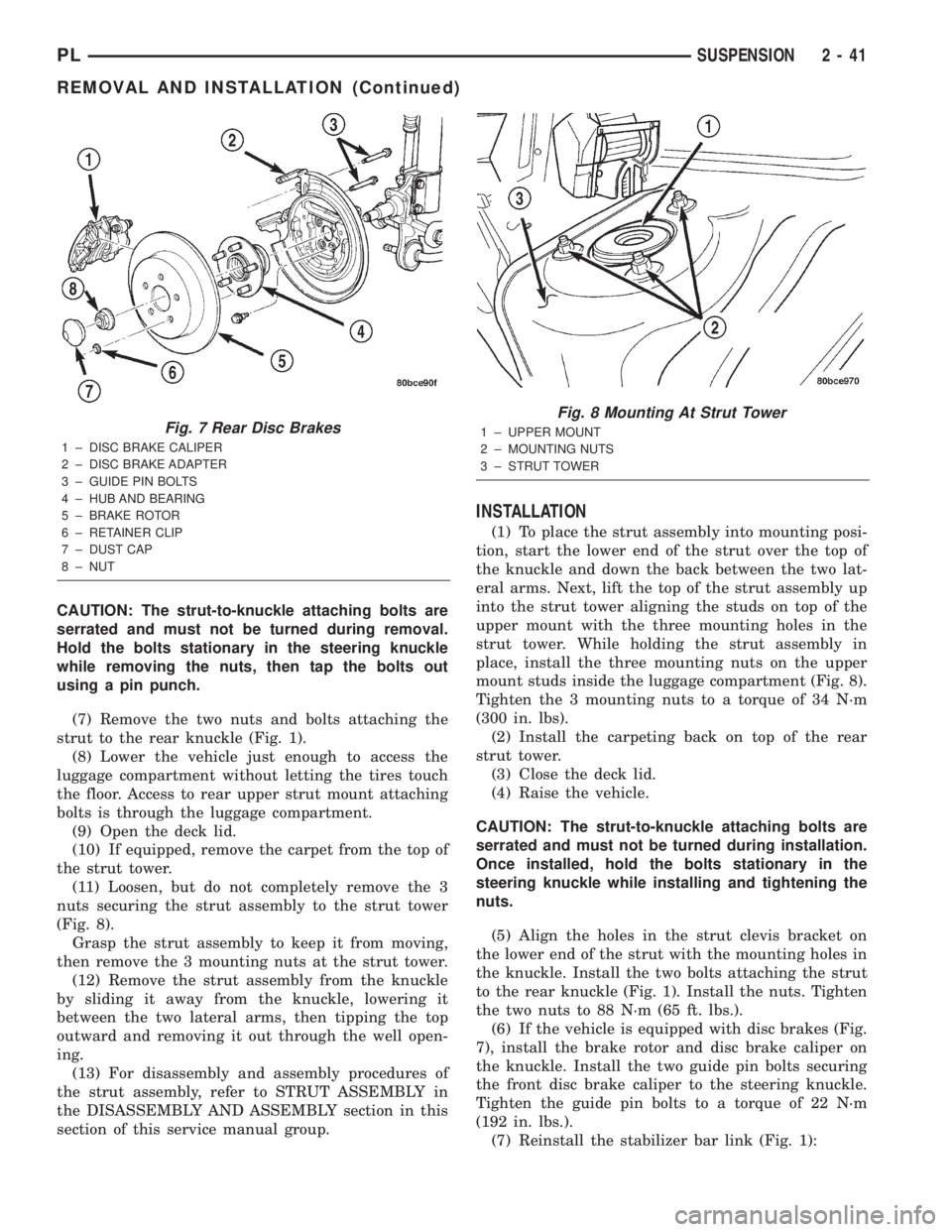
(6) If the vehicle is equipped with rear disc brakes
(Fig. 7), perform the following:
²Remove the two guide pin bolts securing the
front disc brake caliper to the steering knuckle.
²Remove the disc brake caliper from the knuckle
and brake rotor.²Hang the caliper out of the way using a wire
hanger or cord. Do not support the caliper by letting
it hang by the hydraulic hose.
Fig. 5 Rear of Strut Assembly
1 ± BRAKE HOSE BRACKET SCREW
2 ± STABILIZER BAR LINK
3 ± NUT
4 ± STRUT ASSEMBLY
Fig. 6 Rear of Strut Assembly with ABS
1 ± ABS WHEEL SPEED SENSOR BRACKET SCREW
2 ± STABILIZER BAR LINK
3 ± NUT
4 ± STRUT ASSEMBLY
2 - 40 SUSPENSIONPL
Page 52 of 1285
CAUTION: The strut-to-knuckle attaching bolts are
serrated and must not be turned during removal.
Hold the bolts stationary in the steering knuckle
while removing the nuts, then tap the bolts out
using a pin punch.
(7) Remove the two nuts and bolts attaching the
strut to the rear knuckle (Fig. 1).
(8) Lower the vehicle just enough to access the
luggage compartment without letting the tires touch
the floor. Access to rear upper strut mount attaching
bolts is through the luggage compartment.
(9) Open the deck lid.
(10) If equipped, remove the carpet from the top of
the strut tower.
(11) Loosen, but do not completely remove the 3
nuts securing the strut assembly to the strut tower
(Fig. 8).
Grasp the strut assembly to keep it from moving,
then remove the 3 mounting nuts at the strut tower.
(12) Remove the strut assembly from the knuckle
by sliding it away from the knuckle, lowering it
between the two lateral arms, then tipping the top
outward and removing it out through the well open-
ing.
(13) For disassembly and assembly procedures of
the strut assembly, refer to STRUT ASSEMBLY in
the DISASSEMBLY AND ASSEMBLY section in this
section of this service manual group.
INSTALLATION
(1) To place the strut assembly into mounting posi-
tion, start the lower end of the strut over the top of
the knuckle and down the back between the two lat-
eral arms. Next, lift the top of the strut assembly up
into the strut tower aligning the studs on top of the
upper mount with the three mounting holes in the
strut tower. While holding the strut assembly in
place, install the three mounting nuts on the upper
mount studs inside the luggage compartment (Fig. 8).
Tighten the 3 mounting nuts to a torque of 34 N´m
(300 in. lbs).
(2) Install the carpeting back on top of the rear
strut tower.
(3) Close the deck lid.
(4) Raise the vehicle.
CAUTION: The strut-to-knuckle attaching bolts are
serrated and must not be turned during installation.
Once installed, hold the bolts stationary in the
steering knuckle while installing and tightening the
nuts.
(5) Align the holes in the strut clevis bracket on
the lower end of the strut with the mounting holes in
the knuckle. Install the two bolts attaching the strut
to the rear knuckle (Fig. 1). Install the nuts. Tighten
the two nuts to 88 N´m (65 ft. lbs.).
(6) If the vehicle is equipped with disc brakes (Fig.
7), install the brake rotor and disc brake caliper on
the knuckle. Install the two guide pin bolts securing
the front disc brake caliper to the steering knuckle.
Tighten the guide pin bolts to a torque of 22 N´m
(192 in. lbs.).
(7) Reinstall the stabilizer bar link (Fig. 1):
Fig. 7 Rear Disc Brakes
1 ± DISC BRAKE CALIPER
2 ± DISC BRAKE ADAPTER
3 ± GUIDE PIN BOLTS
4 ± HUB AND BEARING
5 ± BRAKE ROTOR
6 ± RETAINER CLIP
7 ± DUST CAP
8 ± NUT
Fig. 8 Mounting At Strut Tower
1 ± UPPER MOUNT
2 ± MOUNTING NUTS
3 ± STRUT TOWER
PLSUSPENSION 2 - 41
REMOVAL AND INSTALLATION (Continued)