2000 DODGE NEON suspension
[x] Cancel search: suspensionPage 37 of 1285
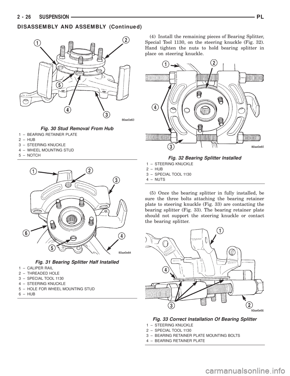
(4) Install the remaining pieces of Bearing Splitter,
Special Tool 1130, on the steering knuckle (Fig. 32).
Hand tighten the nuts to hold bearing splitter in
place on steering knuckle.
(5) Once the bearing splitter in fully installed, be
sure the three bolts attaching the bearing retainer
plate to steering knuckle (Fig. 33) are contacting the
bearing splitter (Fig. 33). The bearing retainer plate
should not support the steering knuckle or contact
the bearing splitter.
Fig. 30 Stud Removal From Hub
1 ± BEARING RETAINER PLATE
2 ± HUB
3 ± STEERING KNUCKLE
4 ± WHEEL MOUNTING STUD
5 ± NOTCH
Fig. 31 Bearing Splitter Half Installed
1 ± CALIPER RAIL
2 ± THREADED HOLE
3 ± SPECIAL TOOL 1130
4 ± STEERING KNUCKLE
5 ± HOLE FOR WHEEL MOUNTING STUD
6 ± HUB
Fig. 32 Bearing Splitter Installed
1 ± STEERING KNUCKLE
2 ± HUB
3 ± SPECIAL TOOL 1130
4 ± NUTS
Fig. 33 Correct Installation Of Bearing Splitter
1 ± STEERING KNUCKLE
2 ± SPECIAL TOOL 1130
3 ± BEARING RETAINER PLATE MOUNTING BOLTS
4 ± BEARING RETAINER PLATE
2 - 26 SUSPENSIONPL
DISASSEMBLY AND ASSEMBLY (Continued)
Page 38 of 1285
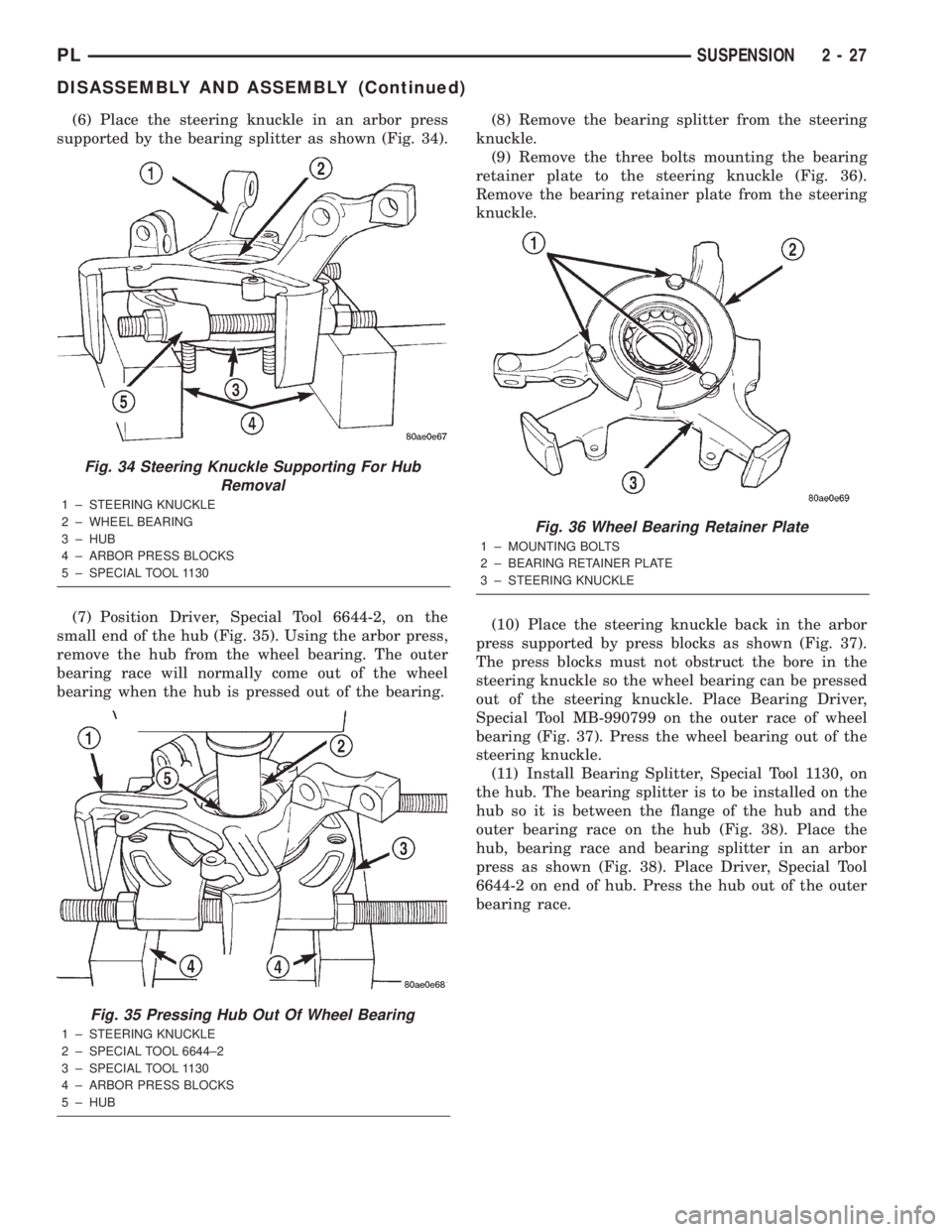
(6) Place the steering knuckle in an arbor press
supported by the bearing splitter as shown (Fig. 34).
(7) Position Driver, Special Tool 6644-2, on the
small end of the hub (Fig. 35). Using the arbor press,
remove the hub from the wheel bearing. The outer
bearing race will normally come out of the wheel
bearing when the hub is pressed out of the bearing.(8) Remove the bearing splitter from the steering
knuckle.
(9) Remove the three bolts mounting the bearing
retainer plate to the steering knuckle (Fig. 36).
Remove the bearing retainer plate from the steering
knuckle.
(10) Place the steering knuckle back in the arbor
press supported by press blocks as shown (Fig. 37).
The press blocks must not obstruct the bore in the
steering knuckle so the wheel bearing can be pressed
out of the steering knuckle. Place Bearing Driver,
Special Tool MB-990799 on the outer race of wheel
bearing (Fig. 37). Press the wheel bearing out of the
steering knuckle.
(11) Install Bearing Splitter, Special Tool 1130, on
the hub. The bearing splitter is to be installed on the
hub so it is between the flange of the hub and the
outer bearing race on the hub (Fig. 38). Place the
hub, bearing race and bearing splitter in an arbor
press as shown (Fig. 38). Place Driver, Special Tool
6644-2 on end of hub. Press the hub out of the outer
bearing race.
Fig. 34 Steering Knuckle Supporting For Hub
Removal
1 ± STEERING KNUCKLE
2 ± WHEEL BEARING
3 ± HUB
4 ± ARBOR PRESS BLOCKS
5 ± SPECIAL TOOL 1130
Fig. 35 Pressing Hub Out Of Wheel Bearing
1 ± STEERING KNUCKLE
2 ± SPECIAL TOOL 6644±2
3 ± SPECIAL TOOL 1130
4 ± ARBOR PRESS BLOCKS
5 ± HUB
Fig. 36 Wheel Bearing Retainer Plate
1 ± MOUNTING BOLTS
2 ± BEARING RETAINER PLATE
3 ± STEERING KNUCKLE
PLSUSPENSION 2 - 27
DISASSEMBLY AND ASSEMBLY (Continued)
Page 39 of 1285
ASSEMBLY
(1) Wipe the bore of the steering knuckle clean of
any grease or dirt with a clean, dry shop towel.
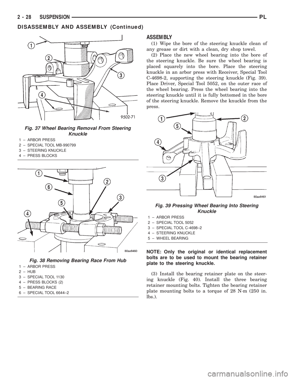
(2) Place the new wheel bearing into the bore of
the steering knuckle. Be sure the wheel bearing is
placed squarely into the bore. Place the steering
knuckle in an arbor press with Receiver, Special Tool
C-4698-2, supporting the steering knuckle (Fig. 39).
Place Driver, Special Tool 5052, on the outer race of
the wheel bearing. Press the wheel bearing into the
steering knuckle until it is fully bottomed in the bore
of the steering knuckle. Remove the knuckle from the
press.
NOTE: Only the original or identical replacement
bolts are to be used to mount the bearing retainer
plate to the steering knuckle.
(3) Install the bearing retainer plate on the steer-
ing knuckle (Fig. 40). Install the three bearing
retainer mounting bolts. Tighten the bearing retainer
plate mounting bolts to a torque of 28 N´m (250 in.
lbs.).
Fig. 37 Wheel Bearing Removal From Steering
Knuckle
1 ± ARBOR PRESS
2 ± SPECIAL TOOL MB-990799
3 ± STEERING KNUCKLE
4 ± PRESS BLOCKS
Fig. 38 Removing Bearing Race From Hub
1 ± ARBOR PRESS
2 ± HUB
3 ± SPECIAL TOOL 1130
4 ± PRESS BLOCKS (2)
5 ± BEARING RACE
6 ± SPECIAL TOOL 6644±2
Fig. 39 Pressing Wheel Bearing Into Steering
Knuckle
1 ± ARBOR PRESS
2 ± SPECIAL TOOL 5052
3 ± SPECIAL TOOL C-4698±2
4 ± STEERING KNUCKLE
5 ± WHEEL BEARING
2 - 28 SUSPENSIONPL
DISASSEMBLY AND ASSEMBLY (Continued)
Page 40 of 1285
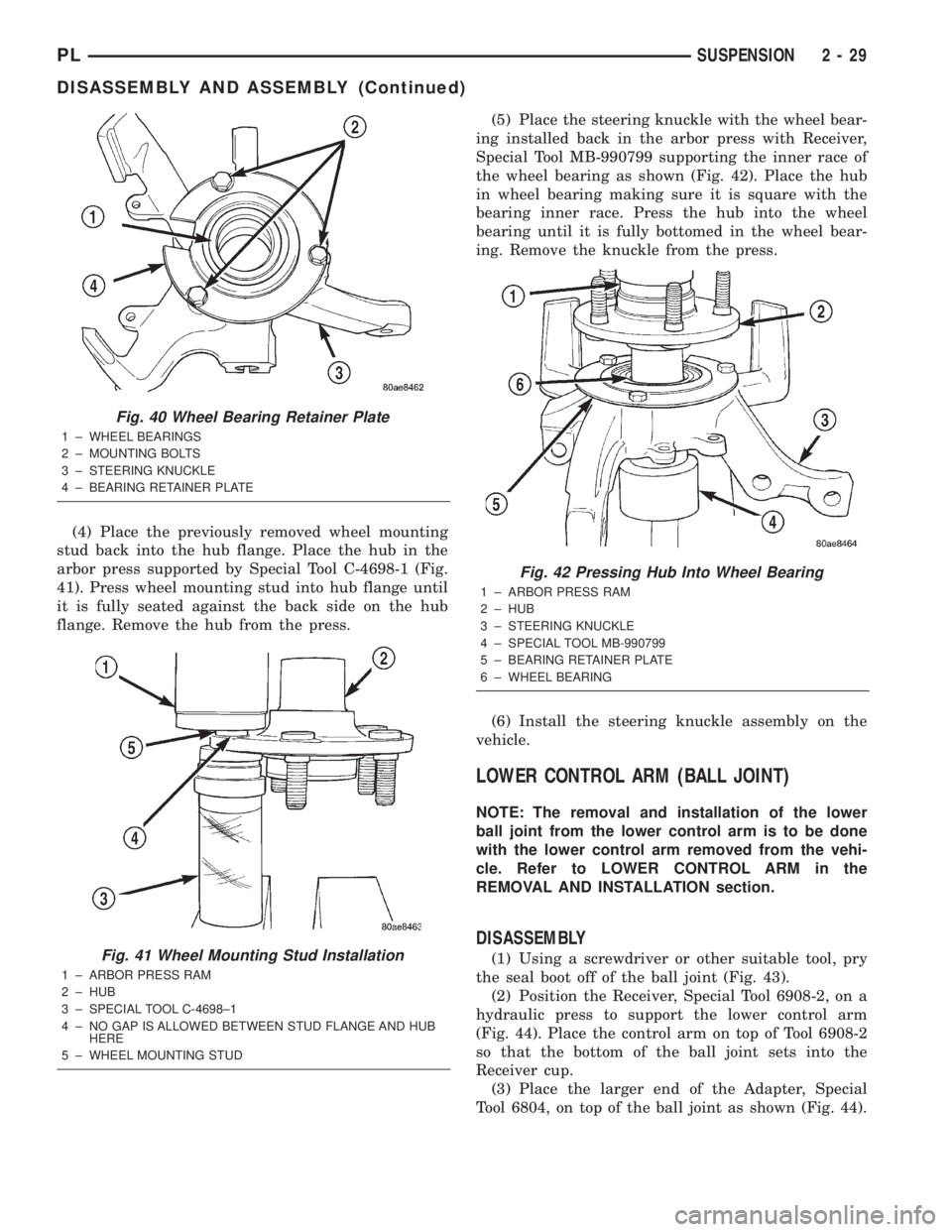
(4) Place the previously removed wheel mounting
stud back into the hub flange. Place the hub in the
arbor press supported by Special Tool C-4698-1 (Fig.
41). Press wheel mounting stud into hub flange until
it is fully seated against the back side on the hub
flange. Remove the hub from the press.(5) Place the steering knuckle with the wheel bear-
ing installed back in the arbor press with Receiver,
Special Tool MB-990799 supporting the inner race of
the wheel bearing as shown (Fig. 42). Place the hub
in wheel bearing making sure it is square with the
bearing inner race. Press the hub into the wheel
bearing until it is fully bottomed in the wheel bear-
ing. Remove the knuckle from the press.
(6) Install the steering knuckle assembly on the
vehicle.
LOWER CONTROL ARM (BALL JOINT)
NOTE: The removal and installation of the lower
ball joint from the lower control arm is to be done
with the lower control arm removed from the vehi-
cle. Refer to LOWER CONTROL ARM in the
REMOVAL AND INSTALLATION section.
DISASSEMBLY
(1) Using a screwdriver or other suitable tool, pry
the seal boot off of the ball joint (Fig. 43).
(2) Position the Receiver, Special Tool 6908-2, on a
hydraulic press to support the lower control arm
(Fig. 44). Place the control arm on top of Tool 6908-2
so that the bottom of the ball joint sets into the
Receiver cup.
(3) Place the larger end of the Adapter, Special
Tool 6804, on top of the ball joint as shown (Fig. 44).
Fig. 40 Wheel Bearing Retainer Plate
1 ± WHEEL BEARINGS
2 ± MOUNTING BOLTS
3 ± STEERING KNUCKLE
4 ± BEARING RETAINER PLATE
Fig. 41 Wheel Mounting Stud Installation
1 ± ARBOR PRESS RAM
2 ± HUB
3 ± SPECIAL TOOL C-4698±1
4 ± NO GAP IS ALLOWED BETWEEN STUD FLANGE AND HUB
HERE
5 ± WHEEL MOUNTING STUD
Fig. 42 Pressing Hub Into Wheel Bearing
1 ± ARBOR PRESS RAM
2 ± HUB
3 ± STEERING KNUCKLE
4 ± SPECIAL TOOL MB-990799
5 ± BEARING RETAINER PLATE
6 ± WHEEL BEARING
PLSUSPENSION 2 - 29
DISASSEMBLY AND ASSEMBLY (Continued)
Page 41 of 1285
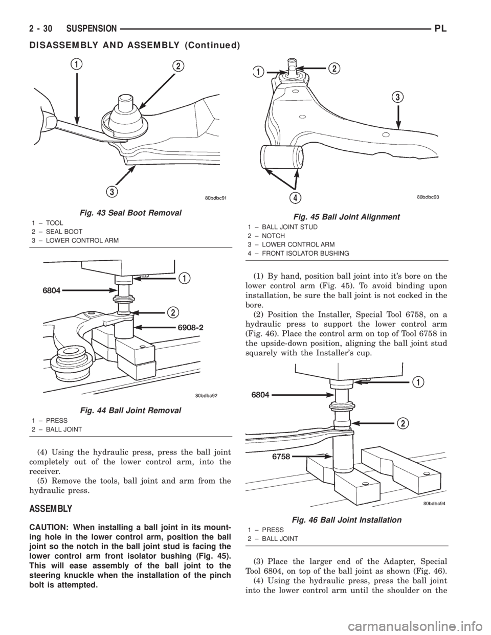
(4) Using the hydraulic press, press the ball joint
completely out of the lower control arm, into the
receiver.
(5) Remove the tools, ball joint and arm from the
hydraulic press.
ASSEMBLY
CAUTION: When installing a ball joint in its mount-
ing hole in the lower control arm, position the ball
joint so the notch in the ball joint stud is facing the
lower control arm front isolator bushing (Fig. 45).
This will ease assembly of the ball joint to the
steering knuckle when the installation of the pinch
bolt is attempted.(1) By hand, position ball joint into it's bore on the
lower control arm (Fig. 45). To avoid binding upon
installation, be sure the ball joint is not cocked in the
bore.
(2) Position the Installer, Special Tool 6758, on a
hydraulic press to support the lower control arm
(Fig. 46). Place the control arm on top of Tool 6758 in
the upside-down position, aligning the ball joint stud
squarely with the Installer's cup.
(3) Place the larger end of the Adapter, Special
Tool 6804, on top of the ball joint as shown (Fig. 46).
(4) Using the hydraulic press, press the ball joint
into the lower control arm until the shoulder on the
Fig. 43 Seal Boot Removal
1±TOOL
2 ± SEAL BOOT
3 ± LOWER CONTROL ARM
Fig. 44 Ball Joint Removal
1 ± PRESS
2 ± BALL JOINT
Fig. 45 Ball Joint Alignment
1 ± BALL JOINT STUD
2 ± NOTCH
3 ± LOWER CONTROL ARM
4 ± FRONT ISOLATOR BUSHING
Fig. 46 Ball Joint Installation
1 ± PRESS
2 ± BALL JOINT
2 - 30 SUSPENSIONPL
DISASSEMBLY AND ASSEMBLY (Continued)
Page 42 of 1285
ball joint bottoms against the lower control arm ball
joint bore. Do not apply excessive pressure against
ball joint and lower control arm once the ball joint
bottoms.
(5) Remove the tools and arm from the hydraulic
press.
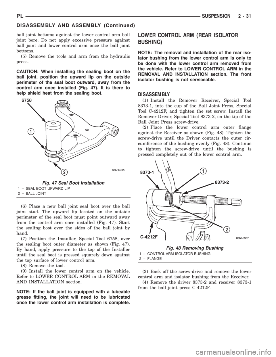
CAUTION: When installing the sealing boot on the
ball joint, position the upward lip on the outside
perimeter of the seal boot outward, away from the
control arm once installed (Fig. 47). It is there to
help shield heat from the sealing boot.
(6) Place a new ball joint seal boot over the ball
joint stud. The upward lip located on the outside
perimeter of the seal boot must point outward away
from the control arm once installed (Fig. 47). Start
the sealing boot over the sides of the ball joint by
hand.
(7) Position the Installer, Special Tool 6758, over
the sealing boot outer diameter as shown (Fig. 47).
By hand, apply pressure to the top of the Installer
until the seal boot is pressed squarely down against
the top surface of lower control arm.
(8) Remove the tool.
(9) Install the lower control arm on the vehicle.
Refer to LOWER CONTROL ARM in the REMOVAL
AND INSTALLATION section.
NOTE: If the ball joint is equipped with a lubeable
grease fitting, the joint will need to be lubricated
once the lower control arm installation is complete.LOWER CONTROL ARM (REAR ISOLATOR
BUSHING)
NOTE: The removal and installation of the rear iso-
lator bushing from the lower control arm is only to
be done with the lower control arm removed from
the vehicle. Refer to LOWER CONTROL ARM in the
REMOVAL AND INSTALLATION section. The front
isolator bushing is not serviceable.
DISASSEMBLY
(1) Install the Remover Receiver, Special Tool
8373-1, into the cup of the Ball Joint Press, Special
Tool C-4212F, and tighten the set screw. Install the
Remover Driver, Special Tool 8373-2, on the tip of the
Ball Joint Press screw-drive.
(2) Place the lower control arm outer flange
against the Receiver as shown (Fig. 48). Tighten the
screw-drive until the Driver contacts the outer cir-
cumference of the bushing evenly (Fig. 48). Continue
to tighten the screw-drive until the bushing is
pressed completely out of the lower control arm.
(3) Back off the screw-drive and remove the lower
control arm and isolator bushing from the Receiver.
(4) Remove the driver 8373-2 and receiver 8373-1
from the ball joint press C-4212F.
Fig. 47 Seal Boot Installation
1 ± SEAL BOOT UPWARD LIP
2 ± BALL JOINT
Fig. 48 Removing Bushing
1 ± CONTROL ARM ISOLATOR BUSHING
2 ± FLANGE
PLSUSPENSION 2 - 31
DISASSEMBLY AND ASSEMBLY (Continued)
Page 43 of 1285
ASSEMBLY
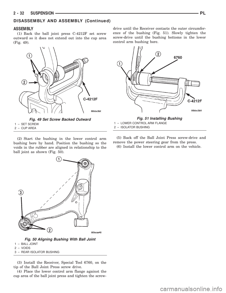
(1) Back the ball joint press C-4212F set screw
outward so it does not extend out into the cup area
(Fig. 49).
(2) Start the bushing in the lower control arm
bushing bore by hand. Position the bushing so the
voids in the rubber are aligned in relationship to the
ball joint as shown (Fig. 50).
(3) Install the Receiver, Special Tool 6760, on the
tip of the Ball Joint Press screw drive.
(4) Place the lower control arm flange against the
cup area of the ball joint press and tighten the screw-drive until the Receiver contacts the outer circumfer-
ence of the bushing (Fig. 51). Slowly tighten the
screw-drive until the bushing bottoms in the lower
control arm bushing bore.
(5) Back off the Ball Joint Press screw-drive and
remove the power steering gear from the press.
(6) Install the lower control arm on the vehicle.
Fig. 49 Set Screw Backed Outward
1 ± SET SCREW
2 ± CUP AREA
Fig. 50 Aligning Bushing With Ball Joint
1 ± BALL JOINT
2 ± VOIDS
3 ± REAR ISOLATOR BUSHING
Fig. 51 Installing Bushing
1 ± LOWER CONTROL ARM FLANGE
2 ± ISOLATOR BUSHING
2 - 32 SUSPENSIONPL
DISASSEMBLY AND ASSEMBLY (Continued)
Page 44 of 1285
SPECIFICATIONS
FRONT SUSPENSION FASTENER TORQUE
SPECIFICATIONS
DESCRIPTION TORQUE
STRUT ASSEMBLY:
Tower Nuts............. 34N´m(300 in. lbs.)
Steering Knuckle Nuts.............. 54N´m
(40 ft. lbs.) + 90É Turn
Strut Shaft Nut........... 75N´m(55ft.lbs.)
STEERING KNUCKLE:
Ball Joint Stud Pinch Bolt Nut........ 95N´m
(70 ft. lbs.)
Disc Brake Caliper Guide Bolts........ 22N´m
(192 in. lbs.)
WHEEL BEARING AND HUB:
Bearing Retainer Plate Bolts.......... 28N´m
(250 in. lbs.)
Driveshaft Hub Nut...... 244N´m(180 ft. lbs.)
Wheel Mounting Nuts...........109-150 N´m
(80-110 ft. lbs.)
STEERING GEAR:
Crossmember Bolts........ 68N´m(50ft.lbs.)
Tie Rod Adjusting Jam Nut . . 75 N´m (55 ft. lbs.)
Tie Rod End Steering Knuckle Nut..... 54N´m
(40 ft. lbs.)
LOWER CONTROL ARM:
Front Pivot Bolt......... 163N´m(120 ft. lbs.)
Rear Pivot Bolt......... 203N´m(150 ft. lbs.)
STABILIZER BAR:
Cushion Retainer Bolts.... 28N´m(250 in. lbs.)
Link Nut............... 23N´m(200 in. lbs.)
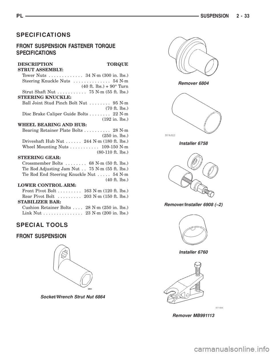
SPECIAL TOOLS
FRONT SUSPENSION
Socket/Wrench Strut Nut 6864
Remover 6804
Installer 6758
Remover/Installer 6908 (±2)
Installer 6760
Remover MB991113
PLSUSPENSION 2 - 33