2000 DODGE NEON suspension
[x] Cancel search: suspensionPage 896 of 1285
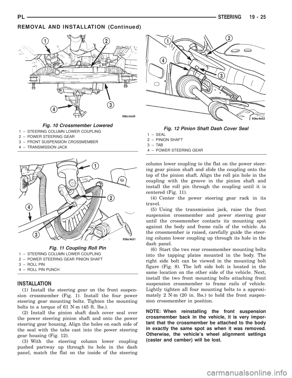
INSTALLATION
(1) Install the steering gear on the front suspen-
sion crossmember (Fig. 1). Install the four power
steering gear mounting bolts. Tighten the mounting
bolts to a torque of 61 N´m (45 ft. lbs.).
(2) Install the pinion shaft dash cover seal over
the power steering pinion shaft and onto the power
steering gear housing. Align the holes on each side of
the seal with the tabs cast into the power steering
gear housing (Fig. 12).
(3) With the steering column lower coupling
pushed partway up through its hole in the dash
panel, match the flat on the inside of the steeringcolumn lower coupling to the flat on the power steer-
ing gear pinion shaft and slide the coupling onto the
top of the pinion shaft. Align the roll pin hole in the
coupling with the groove in the pinion shaft and
install the roll pin through the coupling until it is
centered (Fig. 11).
(4) Center the power steering gear rack in its
travel.
(5) Using the transmission jack, raise the front
suspension crossmember and power steering gear
until the crossmember contacts its mounting spot
against the body and frame rails of the vehicle. As
the crossmember is raised, carefully guide the steer-
ing column lower coupling up through its hole in the
dash panel.
(6) Start the two rear crossmember mounting bolts
into the tapping plates mounted in the body. The
right side bolt can be viewed in the mounting bolt
figure (Fig. 8). The left side bolt is located in the
same location on the other side of the vehicle. Next,
install the two front mounting bolts attaching front
suspension crossmember to frame rails of vehicle.
Lightly tighten all four mounting bolts to a approxi-
mately 2 N´m (20 in. lbs.) to hold the front suspen-
sion crossmember in position.
NOTE: When reinstalling the front suspension
crossmember back in the vehicle, it is very impor-
tant that the crossmember be attached to the body
in exactly the same spot as when it was removed.
Otherwise, the vehicle's wheel alignment settings
(caster and camber) will be lost.
Fig. 10 Crossmember Lowered
1 ± STEERING COLUMN LOWER COUPLING
2 ± POWER STEERING GEAR
3 ± FRONT SUSPENSION CROSSMEMBER
4 ± TRANSMISSION JACK
Fig. 11 Coupling Roll Pin
1 ± STEERING COLUMN LOWER COUPLING
2 ± POWER STEERING GEAR PINION SHAFT
3 ± ROLL PIN
4 ± ROLL PIN PUNCH
Fig. 12 Pinion Shaft Dash Cover Seal
1 ± SEAL
2 ± PINION SHAFT
3±TAB
4 ± POWER STEERING GEAR
PLSTEERING 19 - 25
REMOVAL AND INSTALLATION (Continued)
Page 897 of 1285
(7) Using a soft face hammer, tap the front suspen-
sion crossmember back-and-forth or side-to-side until
it is aligned with the previously scribed positioning
marks on the body of the vehicle (Fig. 9). Once the
front suspension crossmember is correctly positioned,
tighten the rear two crossmember (and rear lower
control arm) mounting bolts to a torque of 203 N´m
(150 ft. lbs.), then tighten the front two crossmember
mounting bolts to a torque of 142 N´m (105 ft. lbs.).
(8) Fasten the engine torque strut to the right for-
ward corner of the front suspension crossmember
using its mounting bolt (Fig. 8). Follow the procedure
described in the ENGINE service manual group to
properly align and tighten the torque strut and it's
mounting bolts.
(9) Using a lint free towel, wipe clean the open
power steering hose ends and the power steering
gear ports. Replace the pressure hose used O-ring
with new. Lubricate the O-ring with power steering
fluid.
(10) Attach the power steering fluid pressure hose
to it's port on the power steering gear (Fig. 7). Start
the tube nut threads into the gear, but do not tighten
them at this time. On vehicles equipped with a power
steering fluid cooler, reconnect the cooler line to the
gear in place of the power steering fluid return hose.
(11) Open the routing clips on the front of the
steering gear housing and install the power steering
fluid pressure hose into the routing clips.
(12) On vehicles equipped with a power steering
fluid cooler, place the cooler in mounting position and
snap the cooler tube going to the gear into the right
routing clip.
(13) Close both routing clips.
(14) Tighten the power steering fluid pressure
hose tube nut at the gear to a torque of 34 N´m (25
ft. lbs.).
(15) If the vehicle is equipped with a power steer-
ing fluid cooler, install the two screws securing the
cooler to the front suspension crossmember. They are
located behind the cooler.
(16) On vehicle's with a power steering fluid cooler,
place the hose clamp on the hose far enough from the
end to clear the steel fitting on the gear. Do the same
for the fluid return hose on a vehicle that is not
equipped with a cooler.
(17) Push either hose listed in the above step onto
the steel fitting, then move and secure the clamp on
the hose past the bead on the steel fitting in the
steering gears outlet port (Fig. 7).
(18) Route the fluid return hose along the front of
the steering gear, clipping it into place in the
C-clamps on the outside of the routing clips on the
front of the power steering gear housing.
(19) Reconnect the wiring harness connector from
the power steering fluid pressure switch (Fig. 6). Besure the locking tab on the wiring harness connector
is securely latched.
(20) Perform the following to each outer tie rod:
²Place the tie rod heat shield on the knuckle's
steering arm, aligning the hole in the shield with the
hole in the knuckle and the tangs on the outside of
the shield with the outside configuration of the steer-
ing arm. The shield should now be facing outboard,
away from the power steering gear and tie rod (Fig.
4).
²Attach the outer tie rod end to its steering
knuckle.
²Start the attaching nut onto the stud of the
outer tie rod.
²While holding the stud of the tie rod stationary
with a wrench, tighten the attaching nut (Fig. 4).
²Using a crowfoot wrench attached to a torque
wrench, tighten the attaching nut to 55 N´m (40 ft.
lbs.).
(21) Install the tire and wheel assemblies back on
vehicle. Tighten the wheel mounting nuts to 135 N´m
(100 ft. lbs.) torque.
(22) Lower the vehicle to ground level.
(23) Install the dash-to-lower coupling seal in
place over the lower coupling's plastic collar.
NOTE: Verify that grease is present on the lip of
the dash-to-coupling seal where it contacts the cou-
pling's plastic collar.
(24) Inside the passenger compartment, reconnect
the steering column lower coupling to the steering
column upper coupling (Fig. 3). Install the coupling
pinch bolt and tighten the pinch bolt nut to a torque
of 28 N´m (250 in. lbs.). Install the pinch bolt
retainer pin.
(25) Remove the steering wheel holder.
(26) While looking under the instrument panel at
the lower coupling, rotate the steering wheel back-
and-forth to verify that the lower coupling does not
squeak against the dash-to-coupling seal.
(27) Perform the POWER STEERING PUMP INI-
TIAL OPERATION service procedure which can be
found in the POWER STEERING PUMP section of
this group to properly fill and bleed the power steer-
ing system.
(28) Check for fluid leaks.
(29) Adjust the front toe setting on the vehicle.
Refer to WHEEL ALIGNMENT in the SUSPENSION
service manual group.
OUTER TIE ROD
REMOVAL
(1) Raise the vehicle. Refer to HOISTING in the
LUBRICATION AND MAINTENANCE group in this
service manual for the correct lifting procedure.
19 - 26 STEERINGPL
REMOVAL AND INSTALLATION (Continued)
Page 899 of 1285
(9) While holding the stud of the tie rod stationary
with a wrench, tighten the attaching nut (Fig. 14).
(10) Using a crowfoot wrench attached to a torque
wrench, tighten the attaching nut to 75 N´m (55 ft.
lbs.).
(11) Install the tire and wheel assembly.
(12) Lower the vehicle.
(13) Adjust the front toe setting on the vehicle.
Refer to WHEEL ALIGNMENT in the SUSPENSION
service manual group.
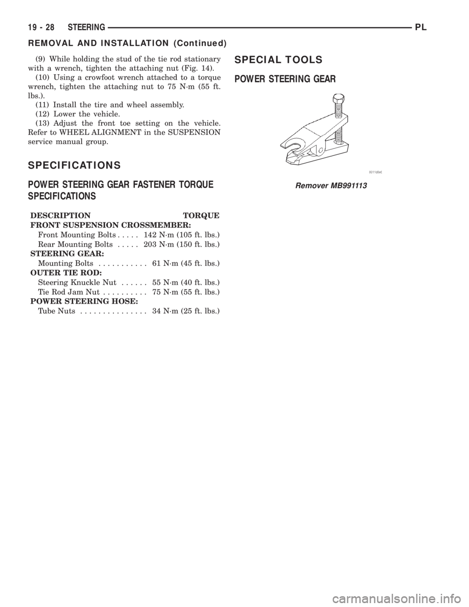
SPECIFICATIONS
POWER STEERING GEAR FASTENER TORQUE
SPECIFICATIONS
DESCRIPTION TORQUE
FRONT SUSPENSION CROSSMEMBER:
Front Mounting Bolts..... 142N´m(105 ft. lbs.)
Rear Mounting Bolts..... 203N´m(150 ft. lbs.)
STEERING GEAR:
Mounting Bolts........... 61N´m(45ft.lbs.)
OUTER TIE ROD:
Steering Knuckle Nut...... 55N´m(40ft.lbs.)
TieRodJamNut .......... 75N´m(55ft.lbs.)
POWER STEERING HOSE:
Tube Nuts............... 34N´m(25ft.lbs.)
SPECIAL TOOLS
POWER STEERING GEAR
Remover MB991113
19 - 28 STEERINGPL
REMOVAL AND INSTALLATION (Continued)
Page 901 of 1285
DIAGNOSIS AND TESTING
STEERING COLUMN
For diagnosis of conditions relating to the steering
column, refer to the STEERING SYSTEM DIAGNO-
SIS CHARTS in DIAGNOSIS AND TESTING in the
POWER STEERING section of this service manual
group.
STEERING COLUMN LOWER COUPLING
The steering column coupling must be inspected
whenever a vehicle is involved in an impact or when-
ever any of the following conditions exist:
²whenever a vehicle is involved in a collision
which deploys the air bag, regardless of the extent of
damage done to the vehicle.
²if a vehicle is involved in an impact of the vehi-
cles front suspension or under carriage, which results
in any type of damage to the front suspension cross-
member.
²under any conditions which result in the steer-
ing column assembly or steering column shaft receiv-
ing a force great enough to move the steering column
or shaft forward or rearward in a vehicle.
STEERING COLUMN COUPLING INSPECTION
PROCEDURE
(1) Place the steering wheel in the STRAIGHT-
AHEAD position. Using a steering wheel holding
clamp, lock the steering wheel in place to keep it
from rotating. This keeps the clockspring in the
proper orientation.
(2) Inside the passenger compartment, remove the
steering column coupling retainer pin, back off the
pinch bolt nut, and remove the steering column cou-
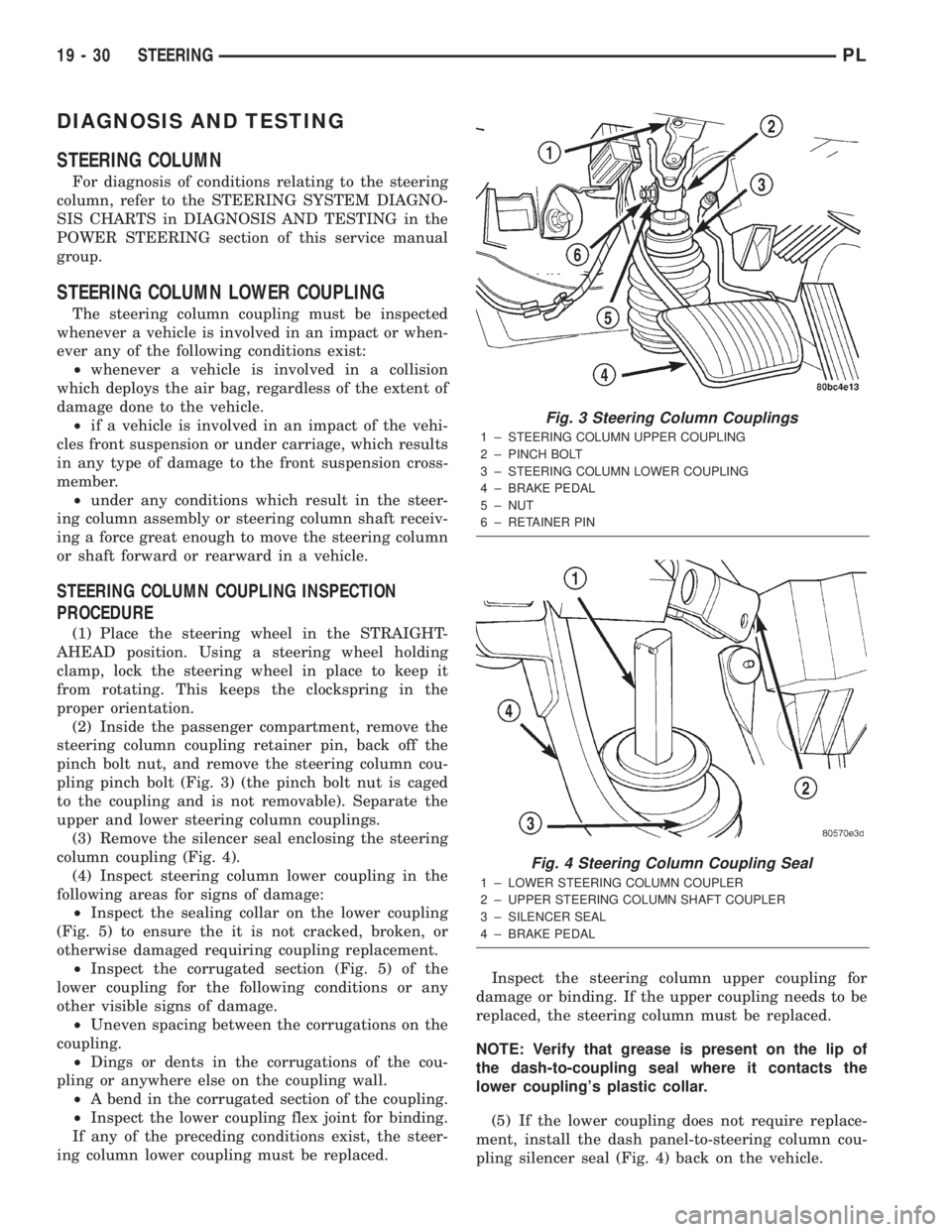
pling pinch bolt (Fig. 3) (the pinch bolt nut is caged
to the coupling and is not removable). Separate the
upper and lower steering column couplings.
(3) Remove the silencer seal enclosing the steering
column coupling (Fig. 4).
(4) Inspect steering column lower coupling in the
following areas for signs of damage:
²Inspect the sealing collar on the lower coupling
(Fig. 5) to ensure the it is not cracked, broken, or
otherwise damaged requiring coupling replacement.
²Inspect the corrugated section (Fig. 5) of the
lower coupling for the following conditions or any
other visible signs of damage.
²Uneven spacing between the corrugations on the
coupling.
²Dings or dents in the corrugations of the cou-
pling or anywhere else on the coupling wall.
²A bend in the corrugated section of the coupling.
²Inspect the lower coupling flex joint for binding.
If any of the preceding conditions exist, the steer-
ing column lower coupling must be replaced.Inspect the steering column upper coupling for
damage or binding. If the upper coupling needs to be
replaced, the steering column must be replaced.
NOTE: Verify that grease is present on the lip of
the dash-to-coupling seal where it contacts the
lower coupling's plastic collar.
(5) If the lower coupling does not require replace-
ment, install the dash panel-to-steering column cou-
pling silencer seal (Fig. 4) back on the vehicle.
Fig. 3 Steering Column Couplings
1 ± STEERING COLUMN UPPER COUPLING
2 ± PINCH BOLT
3 ± STEERING COLUMN LOWER COUPLING
4 ± BRAKE PEDAL
5 ± NUT
6 ± RETAINER PIN
Fig. 4 Steering Column Coupling Seal
1 ± LOWER STEERING COLUMN COUPLER
2 ± UPPER STEERING COLUMN SHAFT COUPLER
3 ± SILENCER SEAL
4 ± BRAKE PEDAL
19 - 30 STEERINGPL
Page 909 of 1285
(25) Turn the key to OFF and remove the scan tool
from the vehicle.
(26) Test the operation of the horn, wipers and any
other functions that are steering column operated. If
applicable, reset the radio and the clock.
(27) If the steering column is a tilt column, verify
the tilt mechanism operates properly.
(28) Road test the vehicle to ensure proper opera-
tion of the steering system and the speed control sys-
tem.
STEERING COLUMN LOWER COUPLING
NOTE: Before proceeding with this removal and
installation procedure, review SERVICE WARNINGS
AND CAUTIONS at the beginning of REMOVAL AND
INSTALLATION in this section and in STEERING
GEAR.
REMOVAL
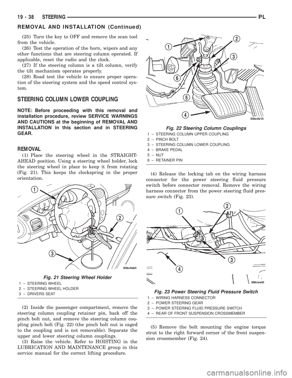
(1) Place the steering wheel in the STRAIGHT-
AHEAD position. Using a steering wheel holder, lock
the steering wheel in place to keep it from rotating
(Fig. 21). This keeps the clockspring in the proper
orientation.
(2) Inside the passenger compartment, remove the
steering column coupling retainer pin, back off the
pinch bolt nut, and remove the steering column cou-
pling pinch bolt (Fig. 22) (the pinch bolt nut is caged
to the coupling and is not removable). Separate the
upper and lower steering column couplings.
(3) Raise the vehicle. Refer to HOISTING in the
LUBRICATION AND MAINTENANCE group in this
service manual for the correct lifting procedure.(4) Release the locking tab on the wiring harness
connector for the power steering fluid pressure
switch before connector removal. Remove the wiring
harness connector from the power steering fluid pres-
sure switch (Fig. 23).
(5) Remove the bolt mounting the engine torque
strut to the right forward corner of the front suspen-
sion crossmember (Fig. 24).
Fig. 21 Steering Wheel Holder
1 ± STEERING WHEEL
2 ± STEERING WHEEL HOLDER
3 ± DRIVERS SEAT
Fig. 22 Steering Column Couplings
1 ± STEERING COLUMN UPPER COUPLING
2 ± PINCH BOLT
3 ± STEERING COLUMN LOWER COUPLING
4 ± BRAKE PEDAL
5 ± NUT
6 ± RETAINER PIN
Fig. 23 Power Steering Fluid Pressure Switch
1 ± WIRING HARNESS CONNECTOR
2 ± POWER STEERING GEAR
3 ± POWER STEERING FLUID PRESSURE SWITCH
4 ± REAR OF FRONT SUSPENSION CROSSMEMBER
19 - 38 STEERINGPL
REMOVAL AND INSTALLATION (Continued)
Page 910 of 1285
NOTE: Before removing the front suspension
crossmember from the vehicle, the location of the
crossmember must be scribed on the body of the
vehicle (Fig. 9). Do this so that the crossmember
can be relocated upon reinstallation against the
body of vehicle in the same location as before
removal. If the front suspension crossmember is
not reinstalled in exactly the same location as
before removal, the preset front wheel alignment
settings (caster and camber) will be lost.
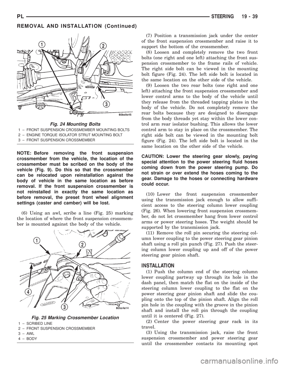
(6) Using an awl, scribe a line (Fig. 25) marking
the location of where the front suspension crossmem-
ber is mounted against the body of the vehicle.(7) Position a transmission jack under the center
of the front suspension crossmember and raise it to
support the bottom of the crossmember.
(8) Loosen and completely remove the two front
bolts (one right and one left) attaching the front sus-
pension crossmember to the frame rails of vehicle.
The right side bolt can be viewed in the mounting
bolt figure (Fig. 24). The left side bolt is located in
the same location on the other side of the vehicle.
(9) Loosen the two rear bolts (one right and one
left) attaching the front suspension crossmember and
lower control arms to the body of the vehicle until
they release from the threaded tapping plates in the
body of the vehicle. Do not completely remove the
rear bolts because they are designed to disengage
from the body threads yet stay within the lower con-
trol arm rear isolator bushing. This allows the lower
control arm to stay in place on the crossmember. The
right side bolt can be viewed in the mounting bolt
figure (Fig. 24). The left side bolt is located in the
same location on the other side of the vehicle.
CAUTION: Lower the steering gear slowly, paying
special attention to the power steering fluid hoses
coming down from the power steering pump. Do
not strain or over extend the hoses coming to the
gear. Damage to the hoses or connecting hardware
could occur.
(10) Lower the front suspension crossmember
using the transmission jack enough to allow suffi-
cient access to the steering column lower coupling
(Fig. 26). When lowering front suspension crossmem-
ber, do not let crossmember hang from lower control
arms or power steering hoses. The weight should be
supported by the transmission jack.
(11) Remove the roll pin securing the steering col-
umn lower coupling to the power steering gear pinion
shaft using a roll pin punch (Fig. 27). Push the steer-
ing column lower coupling up and off of the power
steering gear pinion shaft.
INSTALLATION
(1) Push the column end of the steering column
lower coupling partway up through its hole in the
dash panel, then match the flat on the inside of the
steering column lower coupling to the flat on the
power steering gear pinion shaft and slide the cou-
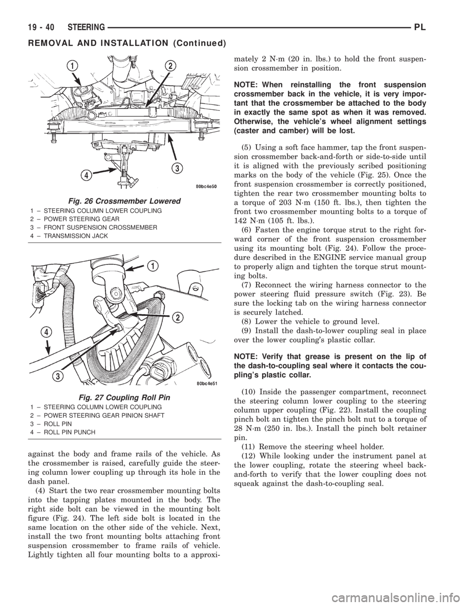
pling onto the top of the pinion shaft. Align the roll
pin hole in the coupling with the groove in the pinion
shaft and install the roll pin through the coupling
until it is centered (Fig. 27).
(2) Center the power steering gear rack in its
travel.
(3) Using the transmission jack, raise the front
suspension crossmember and power steering gear
until the crossmember contacts its mounting spot
Fig. 24 Mounting Bolts
1 ± FRONT SUSPENSION CROSSMEMBER MOUNTING BOLTS
2 ± ENGINE TORQUE ISOLATOR STRUT MOUNTING BOLT
3 ± FRONT SUSPENSION CROSSMEMBER
Fig. 25 Marking Crossmember Location
1 ± SCRIBED LINE
2 ± FRONT SUSPENSION CROSSMEMBER
3±AWL
4 ± BODY
PLSTEERING 19 - 39
REMOVAL AND INSTALLATION (Continued)
Page 911 of 1285
against the body and frame rails of the vehicle. As
the crossmember is raised, carefully guide the steer-
ing column lower coupling up through its hole in the
dash panel.
(4) Start the two rear crossmember mounting bolts
into the tapping plates mounted in the body. The
right side bolt can be viewed in the mounting bolt
figure (Fig. 24). The left side bolt is located in the
same location on the other side of the vehicle. Next,
install the two front mounting bolts attaching front
suspension crossmember to frame rails of vehicle.
Lightly tighten all four mounting bolts to a approxi-mately 2 N´m (20 in. lbs.) to hold the front suspen-
sion crossmember in position.
NOTE: When reinstalling the front suspension
crossmember back in the vehicle, it is very impor-
tant that the crossmember be attached to the body
in exactly the same spot as when it was removed.
Otherwise, the vehicle's wheel alignment settings
(caster and camber) will be lost.
(5) Using a soft face hammer, tap the front suspen-
sion crossmember back-and-forth or side-to-side until
it is aligned with the previously scribed positioning
marks on the body of the vehicle (Fig. 25). Once the
front suspension crossmember is correctly positioned,
tighten the rear two crossmember mounting bolts to
a torque of 203 N´m (150 ft. lbs.), then tighten the
front two crossmember mounting bolts to a torque of
142 N´m (105 ft. lbs.).
(6) Fasten the engine torque strut to the right for-
ward corner of the front suspension crossmember
using its mounting bolt (Fig. 24). Follow the proce-
dure described in the ENGINE service manual group
to properly align and tighten the torque strut mount-
ing bolts.
(7) Reconnect the wiring harness connector to the
power steering fluid pressure switch (Fig. 23). Be
sure the locking tab on the wiring harness connector
is securely latched.
(8) Lower the vehicle to ground level.
(9) Install the dash-to-lower coupling seal in place
over the lower coupling's plastic collar.
NOTE: Verify that grease is present on the lip of
the dash-to-coupling seal where it contacts the cou-
pling's plastic collar.
(10) Inside the passenger compartment, reconnect
the steering column lower coupling to the steering
column upper coupling (Fig. 22). Install the coupling
pinch bolt an tighten the pinch bolt nut to a torque of
28 N´m (250 in. lbs.). Install the pinch bolt retainer
pin.
(11) Remove the steering wheel holder.
(12) While looking under the instrument panel at
the lower coupling, rotate the steering wheel back-
and-forth to verify that the lower coupling does not
squeak against the dash-to-coupling seal.
Fig. 26 Crossmember Lowered
1 ± STEERING COLUMN LOWER COUPLING
2 ± POWER STEERING GEAR
3 ± FRONT SUSPENSION CROSSMEMBER
4 ± TRANSMISSION JACK
Fig. 27 Coupling Roll Pin
1 ± STEERING COLUMN LOWER COUPLING
2 ± POWER STEERING GEAR PINION SHAFT
3 ± ROLL PIN
4 ± ROLL PIN PUNCH
19 - 40 STEERINGPL
REMOVAL AND INSTALLATION (Continued)
Page 1109 of 1285
Pending ConditionsÐThere are not conditions
or situations that prompt conflict or suspension of
testing. The oxygen sensor heater test is not run
pending resolution of MIL illumination due to oxygen
sensor failure.
SuspendÐThere are no conditions which exist for
suspending the Heater Monitor.
CATALYST MONITOR
To comply with clean air regulations, vehicles are
equipped with catalytic converters. These converters
reduce the emission of hydrocarbons, oxides of nitro-
gen and carbon monoxide.
Normal vehicle miles or engine misfire can cause a
catalyst to decay. A meltdown of the ceramic core can
cause a reduction of the exhaust passage. This can
increase vehicle emissions and deteriorate engine
performance, driveability and fuel economy.
The catalyst monitor uses dual oxygen sensors
(O2S's) to monitor the efficiency of the converter. The
dual O2S strategy is based on the fact that as a cat-
alyst deteriorates, its oxygen storage capacity and its
efficiency are both reduced. By monitoring the oxy-
gen storage capacity of a catalyst, its efficiency can
be indirectly calculated. The upstream O2S is used to
detect the amount of oxygen in the exhaust gas
before the gas enters the catalytic converter. The
PCM calculates the A/F mixture from the output of
the O2S. A low voltage indicates high oxygen content
(lean mixture). A high voltage indicates a low content
of oxygen (rich mixture).
When the upstream O2S detects a lean condition,
there is an abundance of oxygen in the exhaust gas.
A functioning converter would store this oxygen so it
can use it for the oxidation of HC and CO. As the
converter absorbs the oxygen, there will be a lack of
oxygen downstream of the converter. The output of
the downstream O2S will indicate limited activity in
this condition.
As the converter loses the ability to store oxygen,
the condition can be detected from the behavior of
the downstream O2S. When the efficiency drops, no
chemical reaction takes place. This means the con-
centration of oxygen will be the same downstream as
upstream. The output voltage of the downstream
O2S copies the voltage of the upstream sensor. The
only difference is a time lag (seen by the PCM)
between the switching of the O2S's.
To monitor the system, the number of lean-to-rich
switches of upstream and downstream O2S's is
counted. The ratio of downstream switches to
upstream switches is used to determine whether the
catalyst is operating properly. An effective catalyst
will have fewer downstream switches than it has
upstream switches i.e., a ratio closer to zero. For atotally ineffective catalyst, this ratio will be one-to-
one, indicating that no oxidation occurs in the device.
The system must be monitored so that when cata-
lyst efficiency deteriorates and exhaust emissions
increase to over the legal limit, the MIL (check
engine lamp) will be illuminated.
Monitor OperationÐTo monitor catalyst effi-
ciency, the PCM expands the rich and lean switch
points of the heated oxygen sensor. With extended
switch points, the air/fuel mixture runs richer and
leaner to overburden the catalytic converter. Once
the test is started, the air/fuel mixture runs rich and
lean and the O2 switches are counted. A switch is
counted when an oxygen sensor signal goes from
below the lean threshold to above the rich threshold.
The number of Rear O2 sensor switches is divided by
the number of Front O2 sensor switches to determine
the switching ratio.
The test runs for 20 seconds. As catalyst efficiency
deteriorated over the life of the vehicle, the switch
rate at the downstream sensor approaches that of the
upstream sensor. If at any point during the test
period the switch ratio reaches a predetermined
value, a counter is incremented by one. The monitor
is enabled to run another test during that trip. When
the test fails three times, the counter increments to
three, a malfunction is entered, and a Freeze Frame
is stored. When the counter increments to three dur-
ing the next trip, the code is matured and the MIL is
illuminated. If the test passes the first, no further
testing is conducted during that trip.
The MIL is extinguished after three consecutive
good trips. The good trip criteria for the catalyst
monitor is more stringent than the failure criteria. In
order to pass the test and increment one good trip,
the downstream sensor switch rate must be less than
80% of the upstream rate (60% for manual transmis-
sions). The failure percentages are 90% and 70%
respectively.
Enabling ConditionsÐThe following conditions
must typically be met before the PCM runs the cat-
alyst monitor. Specific times for each parameter may
be different from engine to engine.
²Accumulated drive time
²Enable time
²Ambient air temperature
²Barometric pressure
²Catalyst warm-up counter
²Engine coolant temperature
²Accumulated throttle position sensor
²Vehicle speed
²MAP
²RPM
²Engine in closed loop
²Fuel level
25 - 22 EMISSION CONTROL SYSTEMSPL
DESCRIPTION AND OPERATION (Continued)