2000 DODGE NEON suspension
[x] Cancel search: suspensionPage 878 of 1285
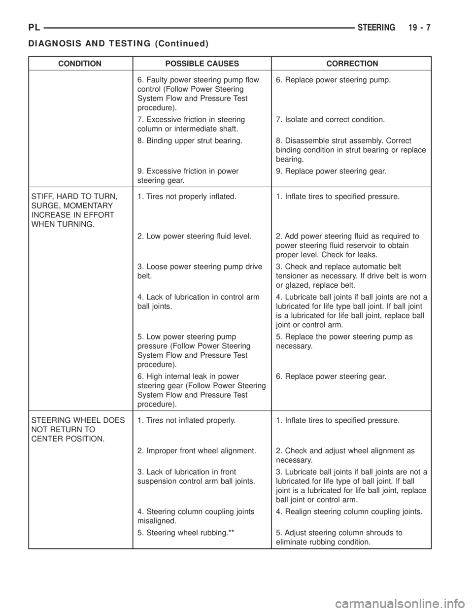
CONDITION POSSIBLE CAUSES CORRECTION
6. Faulty power steering pump flow
control (Follow Power Steering
System Flow and Pressure Test
procedure).6. Replace power steering pump.
7. Excessive friction in steering
column or intermediate shaft.7. Isolate and correct condition.
8. Binding upper strut bearing. 8. Disassemble strut assembly. Correct
binding condition in strut bearing or replace
bearing.
9. Excessive friction in power
steering gear.9. Replace power steering gear.
STIFF, HARD TO TURN,
SURGE, MOMENTARY
INCREASE IN EFFORT
WHEN TURNING.1. Tires not properly inflated. 1. Inflate tires to specified pressure.
2. Low power steering fluid level. 2. Add power steering fluid as required to
power steering fluid reservoir to obtain
proper level. Check for leaks.
3. Loose power steering pump drive
belt.3. Check and replace automatic belt
tensioner as necessary. If drive belt is worn
or glazed, replace belt.
4. Lack of lubrication in control arm
ball joints.4. Lubricate ball joints if ball joints are not a
lubricated for life type ball joint. If ball joint
is a lubricated for life ball joint, replace ball
joint or control arm.
5. Low power steering pump
pressure (Follow Power Steering
System Flow and Pressure Test
procedure).5. Replace the power steering pump as
necessary.
6. High internal leak in power
steering gear (Follow Power Steering
System Flow and Pressure Test
procedure).6. Replace power steering gear.
STEERING WHEEL DOES
NOT RETURN TO
CENTER POSITION.1. Tires not inflated properly. 1. Inflate tires to specified pressure.
2. Improper front wheel alignment. 2. Check and adjust wheel alignment as
necessary.
3. Lack of lubrication in front
suspension control arm ball joints.3. Lubricate ball joints if ball joints are not a
lubricated for life type of ball joint. If ball
joint is a lubricated for life ball joint, replace
ball joint or control arm.
4. Steering column coupling joints
misaligned.4. Realign steering column coupling joints.
5. Steering wheel rubbing.** 5. Adjust steering column shrouds to
eliminate rubbing condition.
PLSTEERING 19 - 7
DIAGNOSIS AND TESTING (Continued)
Page 879 of 1285
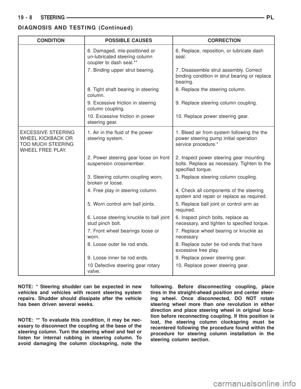
CONDITION POSSIBLE CAUSES CORRECTION
6. Damaged, mis-positioned or
un-lubricated steering column
coupler to dash seal.**6. Replace, reposition, or lubricate dash
seal.
7. Binding upper strut bearing. 7. Disassemble strut assembly. Correct
binding condition in strut bearing or replace
bearing.
8. Tight shaft bearing in steering
column.8. Replace the steering column.
9. Excessive friction in steering
column coupling.9. Replace steering column coupling.
10. Excessive friction in power
steering gear.10. Replace power steering gear.
EXCESSIVE STEERING
WHEEL KICKBACK OR
TOO MUCH STEERING
WHEEL FREE PLAY.1. Air in the fluid of the power
steering system.1. Bleed air from system following the the
power steering pump initial operation
service procedure.*
2. Power steering gear loose on front
suspension crossmember.2. Inspect power steering gear mounting
bolts. Replace as necessary. Tighten to the
specified torque.
3. Steering column coupling worn,
broken or loose.3. Replace steering column coupling.
4. Free play in steering column. 4. Check all components of the steering
system and repair or replace as required.
5. Worn control arm ball joints. 5. Replace ball joint or control arm as
required.
6. Loose steering knuckle to ball joint
stud pinch bolt.6. Inspect pinch bolts, replace as
necessary, and tighten to specified torque.
7. Front wheel bearings loose or
worn.7. Replace wheel bearing or knuckle as
necessary.
8. Loose outer tie rod ends. 8. Replace outer tie rod ends that have
excessive free play.
9. Loose inner tie rod ends. 9. Replace power steering gear.
10 Defective steering gear rotary
valve.10. Replace power steering gear.
NOTE: * Steering shudder can be expected in new
vehicles and vehicles with recent steering system
repairs. Shudder should dissipate after the vehicle
has been driven several weeks.
NOTE: ** To evaluate this condition, it may be nec-
essary to disconnect the coupling at the base of the
steering column. Turn the steering wheel and feel or
listen for internal rubbing in steering column. To
avoid damaging the column clockspring, note thefollowing. Before disconnecting coupling, place
tires in the straight-ahead position and center steer-
ing wheel. Once disconnected, DO NOT rotate
steering wheel more than one revolution in either
direction and place steering wheel in original loca-
tion before reconnecting coupling. If this position is
lost, the steering column clockspring must be
recentered following the procedure found within the
procedure for steering column installation in the
steering column section.
19 - 8 STEERINGPL
DIAGNOSIS AND TESTING (Continued)
Page 882 of 1285
CAUTION: Do not force the pump to operate
against the stops for more than 5 seconds at a time
as pump damage may result.
(6) Completely open the valve on the Power Steer-
ing Analyzer flow meter. Turn the steering wheel to
the extreme left until the stop in the steering gear is
met, then turn the steering wheel to the right until
the right stop is met. Record the highest indicated
pressure at each position. Compare the recorded
readings to the specifications. If the highest output
pressure reading against one stop is within 50 psi of
the highest reading at the other stop, the steering
gear is leaking internally and must be replaced.
If the power steering gear requires replacement,
refer to the section POWER STEERING GEAR
within this group for the removal and installation
procedure.
SERVICE PROCEDURES
POWER STEERING SYSTEM FLUID LEVEL
CHECK
WARNING: FLUID LEVEL SHOULD BE CHECKED
WITH THE ENGINE OFF TO PREVENT PERSONAL
INJURY FROM MOVING PARTS.
Before opening power steering system, wipe the
reservoir filler cap free of dirt and debris. Remove
the cap and check the fluid level on its dipstick.
When the fluid is at normal ambient temperature,
approximately 21ÉC to 27ÉC (70ÉF to 80ÉF), the dip-
stick level should indicateCOLD. Do not overfill the
power steering system. In all power steering systems,
use only Mopar Power Steering Fluid, or its equiva-
lent.
NOTE: Do not use any type of automatic transmis-
sion fluid in the power steering system.
REMOVAL AND INSTALLATION
SERVICE WARNINGS AND CAUTIONS
WARNING: POWER STEERING FLUID, ENGINE
PARTS AND EXHAUST SYSTEM MAY BE
EXTREMELY HOT IF ENGINE HAS BEEN RUNNING.
DO NOT START ENGINE WITH ANY LOOSE OR DIS-
CONNECTED HOSES. DO NOT ALLOW HOSES TO
TOUCH HOT EXHAUST MANIFOLD OR CATALYST.WARNING: FLUID LEVEL SHOULD BE CHECKED
WITH THE ENGINE OFF TO PREVENT PERSONAL
INJURY FROM MOVING PARTS.
CAUTION: When the system is open, cap all open
ends of the hoses, power steering pump fittings or
power steering gear ports to prevent entry of for-
eign material into the components.
NOTE: Do not use any type of automatic transmis-
sion fluid in the power steering system.
POWER STEERING FLUID PRESSURE HOSE
NOTE: Before proceeding with this removal and
installation procedure, review SERVICE WARNINGS
AND CAUTIONS at the beginning of REMOVAL AND
INSTALLATION in this section.
REMOVAL
(1) Siphon as much fluid as possible from the
power steering fluid reservoir.
(2) Raise the vehicle. Refer to HOISTING in the
LUBRICATION AND MAINTENANCE group in this
service manual for the correct lifting procedure.
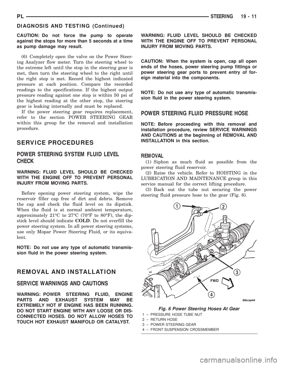
(3) Back out the tube nut securing the power
steering fluid pressure hose to the gear (Fig. 6).
Fig. 6 Power Steering Hoses At Gear
1 ± PRESSURE HOSE TUBE NUT
2 ± RETURN HOSE
3 ± POWER STEERING GEAR
4 ± FRONT SUSPENSION CROSSMEMBER
PLSTEERING 19 - 11
DIAGNOSIS AND TESTING (Continued)
Page 884 of 1285
(4) If the vehicle is not equipped with a power
steering fluid cooler:
²Remove the hose clamp securing the return hose
to the steel fitting in the outlet port on the power
steering gear (Fig. 6).
²Slide the hose off the end of the steel fitting.
²Pull the hose loose from the C-clamps on the two
routing clips located on the front of the steering gear
(Fig. 6).
(5) Lower the vehicle.
(6) Remove the bolt securing the hose routing clip
in place on the right engine mount (Fig. 7). Remove
the power steering fluid return hose from the routing
clip.
(7) Remove the hose clamp securing the return
hose to the power steering fluid reservoir (Fig. 7).
Slide the hose off the end of the reservoir fitting.
(8) Remove the power steering return hose from
the engine compartment.
INSTALLATION
(1) Slide a hose clamp onto the power steering
pump end of the hose far enough to clear the fitting
on the power steering fluid reservoir once the hose is
installed.
(2) Install the power steering return hose into the
engine compartment from the top. First, guide the
pump end of the hose onto the fitting on the power
steering fluid reservoir, then route the rest of the
hose along the right side of the engine (Fig. 7). Guide
the gear end of the hose down behind the back of the
engine towards the power steering gear.
(3) Expand the hose clamp and slide it onto the
fluid reservoir fitting. Secure the clamp once it is
past the bead formed into the fluid reservoir fitting.
(4) Install the power steering fluid return hose in
the hose routing clip and attach the clip to the right
engine mount (Fig. 7). Tighten the hose routing clip
bolt to a torque of 12 N´m (105 in. lbs.).
(5) Raise the vehicle.
CAUTION: The power steering fluid hoses must
remain away from the exhaust system, vehicle com-
ponents, and unfriendly surfaces that can cause
possible damage to the power steering hoses.
(6) Using a lint free towel, wipe clean the open
power steering hose end and the power steering gear
port fitting or power steering fluid cooler port.
(7) Install a hose clamp onto the end of the hose
far enough to clear the fitting on the steering gear or
cooler once the hose is installed.
(8) If the vehicle is equipped with a power steering
fluid cooler, slide the hose onto the end of the cooler
tube. Install the hose clamp past the bead formed
into the cooler tube and secure in place.(9) If the vehicle is not equipped with a power
steering fluid cooler:
²Slide the hose onto the end of the steel fitting in
the steering gear outlet port (Fig. 6).
²Install the hose clamp past the bead formed into
the steel fitting and secure in place.
²Align and attach the hose to the C-clamps on
the two routing clips located on the front of the steer-
ing gear (Fig. 6).
(10) Lower the vehicle.
(11) Perform the POWER STEERING PUMP INI-
TIAL OPERATION service procedure which can be
found in the POWER STEERING PUMP section of
this group to properly fill and bleed the power steer-
ing system.
(12) Check for leaks at all hose connections.
POWER STEERING FLUID COOLER
NOTE: Before proceeding with this removal and
installation procedure, review SERVICE WARNINGS
AND CAUTIONS at the beginning of REMOVAL AND
INSTALLATION in this section.
REMOVAL
(1) Siphon as much fluid as possible from the
power steering fluid reservoir.
(2) Raise the vehicle. Refer to HOISTING in the
LUBRICATION AND MAINTENANCE group in this
service manual for the correct lifting procedure.
(3) Remove the hose clamp, attaching the power
steering fluid return hose to the power steering fluid
cooler. Remove the return hose from the cooler.
(4) Remove the hose clamp attaching the power
steering cooler fluid hose to the steel fitting in the
power steering gear outlet port (Fig. 8).
(5) Remove the two screws securing the cooler to
the front suspension crossmember. They are located
behind the cooler. They can be accessed from above.
(6) Open the routing clip on the right front of the
power steering gear housing and remove the cooler
tube from it.
(7) Remove the cooler from the vehicle.
INSTALLATION
(1) Slide a hose clamp onto the end of the power
steering cooler fluid hose far enough to clear the steel
fitting on the power steering gear once the hose is
installed.
(2) Slide the hose (with cooler attached) onto the
fitting on the steering gear, then align the tube on
back of the cooler with the open routing clip on the
right front of the power steering gear housing, and
snap it into place. Close the clip.
PLSTEERING 19 - 13
REMOVAL AND INSTALLATION (Continued)
Page 885 of 1285

(3) Install the hose clamp on the power steering
cooler fluid hose past the bead formed into the steel
fitting and secure in place.
(4) Install the two screws attaching the cooler to
the front suspension crossmember. Tighten the cooler
attaching screws to a torque of 10 N´m (90 in. lbs.).
(5) Install the power steering fluid return hose on
the power steering fluid cooler tube. Install the hose
clamp on the power steering return hose securing it
to the power steering cooler. Be sure the hose clamp
is installed on the return hose past the bead on the
end of the cooler tube.
(6) Lower the vehicle.
(7) Perform the POWER STEERING PUMP INI-
TIAL OPERATION service procedure which can be
found in the POWER STEERING PUMP section of
this group to properly fill and bleed the power steer-
ing system.
(8) Check for leaks at all connections.
POWER STEERING FLUID PRESSURE SWITCH
NOTE: Before proceeding with this removal and
installation procedure, review SERVICE WARNINGS
AND CAUTIONS at the beginning of REMOVAL AND
INSTALLATION in this section.
REMOVAL
(1) Disconnect negative battery cable from the neg-
ative post of the battery. Be sure cable is isolated
from negative post on battery.(2) Raise the vehicle. Refer to HOISTING in the
LUBRICATION AND MAINTENANCE group in this
service manual for the correct lifting procedure.
(3) Locate the power steering fluid pressure switch
on the back side of the power steering gear (Fig. 9).
(4) Remove the vehicle wiring harness connector
from the power steering fluid pressure switch.
NOTE: When removing and installing the power
steering pressure switch, use a 7/8 inch deep well
socket. The deep well socket will prevent damage
to the plastic electrical connector area of the power
steering fluid pressure switch.
(5) Unscrew and remove the power steering fluid
pressure switch from the power steering gear.
INSTALLATION
(1) By hand, screw the power steering pressure
switch into the power steering gear until it is fully
seated (Fig. 9). Tighten the power steering pressure
switch to a maximum torque of 8 N´m (70 in. lbs.).
Over-torquing will result in stripping the threads out
of the power steering pressure switch port in the
steering gear.
(2) Install the vehicle wiring harness connector. Be
sure the latch on the wiring harness connector is
fully engaged with the locking tab on the power
steering pressure switch.
(3) Lower the vehicle.
(4) Fill the power steering fluid reservoir to the
correct fluid level. Use only MopartPower Steering
Fluid, or equivalent.
(5) Connect the negative cable to the negative post
of the battery.
Fig. 8 Power Steering Fluid Cooler
1 ± POWER STEERING FLUID COOLER
2 ± TRANSAXLE
3 ± CLAMP
4 ± AIR DAM
5 ± CROSSMEMBER
Fig. 9 Switch Location
1 ± WIRING HARNESS CONNECTOR
2 ± POWER STEERING GEAR
3 ± POWER STEERING FLUID PRESSURE SWITCH
4 ± REAR OF FRONT SUSPENSION CROSSMEMBER
19 - 14 STEERINGPL
REMOVAL AND INSTALLATION (Continued)
Page 892 of 1285
STEERING GEAR
TABLE OF CONTENTS
page page
DESCRIPTION AND OPERATION
POWER STEERING GEAR..................21
REMOVAL AND INSTALLATION
SERVICE WARNINGS AND CAUTIONS........22
POWER STEERING GEAR..................22
OUTER TIE ROD.........................26SPECIFICATIONS
POWER STEERING GEAR FASTENER
TORQUE SPECIFICATIONS...............28
SPECIAL TOOLS
POWER STEERING GEAR..................28
DESCRIPTION AND OPERATION
POWER STEERING GEAR
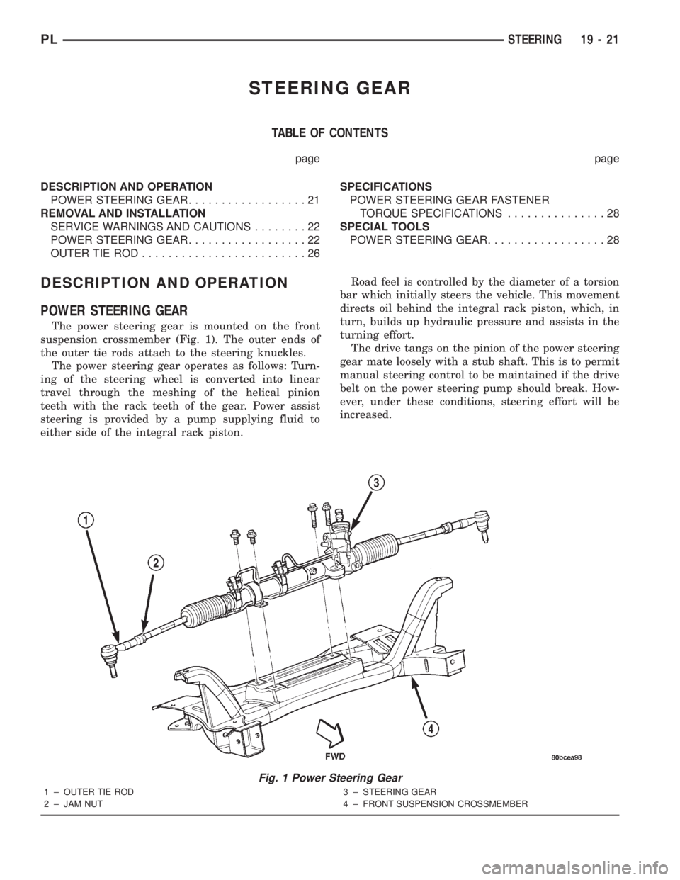
The power steering gear is mounted on the front
suspension crossmember (Fig. 1). The outer ends of
the outer tie rods attach to the steering knuckles.
The power steering gear operates as follows: Turn-
ing of the steering wheel is converted into linear
travel through the meshing of the helical pinion
teeth with the rack teeth of the gear. Power assist
steering is provided by a pump supplying fluid to
either side of the integral rack piston.Road feel is controlled by the diameter of a torsion
bar which initially steers the vehicle. This movement
directs oil behind the integral rack piston, which, in
turn, builds up hydraulic pressure and assists in the
turning effort.
The drive tangs on the pinion of the power steering
gear mate loosely with a stub shaft. This is to permit
manual steering control to be maintained if the drive
belt on the power steering pump should break. How-
ever, under these conditions, steering effort will be
increased.
Fig. 1 Power Steering Gear
1 ± OUTER TIE ROD
2 ± JAM NUT3 ± STEERING GEAR
4 ± FRONT SUSPENSION CROSSMEMBER
PLSTEERING 19 - 21
Page 894 of 1285
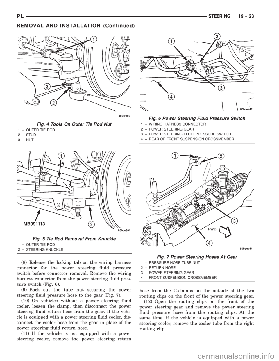
(8) Release the locking tab on the wiring harness
connector for the power steering fluid pressure
switch before connector removal. Remove the wiring
harness connector from the power steering fluid pres-
sure switch (Fig. 6).
(9) Back out the tube nut securing the power
steering fluid pressure hose to the gear (Fig. 7).
(10) On vehicles without a power steering fluid
cooler, loosen the clamp, then disconnect the power
steering fluid return hose from the gear. If the vehi-
cle is equipped with a power steering fluid cooler, dis-
connect the cooler hose from the gear in place of the
power steering fluid return hose.
(11) If the vehicle is not equipped with a power
steering cooler, remove the power steering returnhose from the C-clamps on the outside of the two
routing clips on the front of the power steering gear.
(12) Open the routing clips on the front of the
power steering gear and remove the power steering
fluid pressure hose from the routing clips. At the
same time, if the vehicle is equipped with a power
steering cooler, remove the cooler tube from the right
routing clip.
Fig. 4 Tools On Outer Tie Rod Nut
1 ± OUTER TIE ROD
2 ± STUD
3 ± NUT
Fig. 5 Tie Rod Removal From Knuckle
1 ± OUTER TIE ROD
2 ± STEERING KNUCKLE
Fig. 6 Power Steering Fluid Pressure Switch
1 ± WIRING HARNESS CONNECTOR
2 ± POWER STEERING GEAR
3 ± POWER STEERING FLUID PRESSURE SWITCH
4 ± REAR OF FRONT SUSPENSION CROSSMEMBER
Fig. 7 Power Steering Hoses At Gear
1 ± PRESSURE HOSE TUBE NUT
2 ± RETURN HOSE
3 ± POWER STEERING GEAR
4 ± FRONT SUSPENSION CROSSMEMBER
PLSTEERING 19 - 23
REMOVAL AND INSTALLATION (Continued)
Page 895 of 1285
(13) If the vehicle is equipped with a power steer-
ing fluid cooler, remove the two screws securing the
cooler to the front suspension crossmember. They are
located behind the cooler and can be accessed from
above. Allow the cooler to hang out of the way.
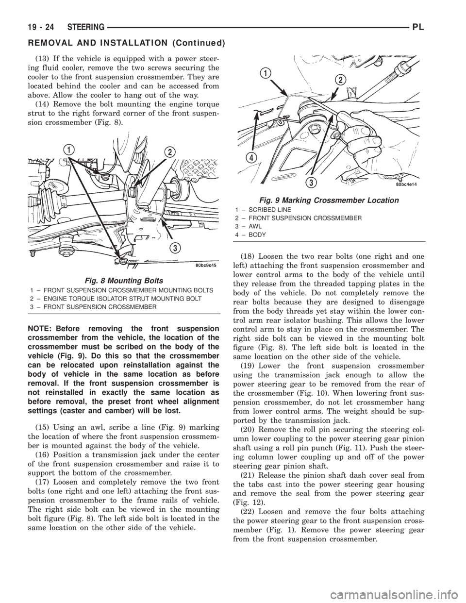
(14) Remove the bolt mounting the engine torque
strut to the right forward corner of the front suspen-
sion crossmember (Fig. 8).
NOTE: Before removing the front suspension
crossmember from the vehicle, the location of the
crossmember must be scribed on the body of the
vehicle (Fig. 9). Do this so that the crossmember
can be relocated upon reinstallation against the
body of vehicle in the same location as before
removal. If the front suspension crossmember is
not reinstalled in exactly the same location as
before removal, the preset front wheel alignment
settings (caster and camber) will be lost.
(15) Using an awl, scribe a line (Fig. 9) marking
the location of where the front suspension crossmem-
ber is mounted against the body of the vehicle.
(16) Position a transmission jack under the center
of the front suspension crossmember and raise it to
support the bottom of the crossmember.
(17) Loosen and completely remove the two front
bolts (one right and one left) attaching the front sus-
pension crossmember to the frame rails of vehicle.
The right side bolt can be viewed in the mounting
bolt figure (Fig. 8). The left side bolt is located in the
same location on the other side of the vehicle.(18) Loosen the two rear bolts (one right and one
left) attaching the front suspension crossmember and
lower control arms to the body of the vehicle until
they release from the threaded tapping plates in the
body of the vehicle. Do not completely remove the
rear bolts because they are designed to disengage
from the body threads yet stay within the lower con-
trol arm rear isolator bushing. This allows the lower
control arm to stay in place on the crossmember. The
right side bolt can be viewed in the mounting bolt
figure (Fig. 8). The left side bolt is located in the
same location on the other side of the vehicle.
(19) Lower the front suspension crossmember
using the transmission jack enough to allow the
power steering gear to be removed from the rear of
the crossmember (Fig. 10). When lowering front sus-
pension crossmember, do not let crossmember hang
from lower control arms. The weight should be sup-
ported by the transmission jack.
(20) Remove the roll pin securing the steering col-
umn lower coupling to the power steering gear pinion
shaft using a roll pin punch (Fig. 11). Push the steer-
ing column lower coupling up and off of the power
steering gear pinion shaft.
(21) Release the pinion shaft dash cover seal from
the tabs cast into the power steering gear housing
and remove the seal from the power steering gear
(Fig. 12).
(22) Loosen and remove the four bolts attaching
the power steering gear to the front suspension cross-
member (Fig. 1). Remove the power steering gear
from the front suspension crossmember.
Fig. 8 Mounting Bolts
1 ± FRONT SUSPENSION CROSSMEMBER MOUNTING BOLTS
2 ± ENGINE TORQUE ISOLATOR STRUT MOUNTING BOLT
3 ± FRONT SUSPENSION CROSSMEMBER
Fig. 9 Marking Crossmember Location
1 ± SCRIBED LINE
2 ± FRONT SUSPENSION CROSSMEMBER
3±AWL
4 ± BODY
19 - 24 STEERINGPL
REMOVAL AND INSTALLATION (Continued)