Page 3884 of 4592

WARRANTY PARTS MARKING PROCEDURE ± PG006-03September 26, 2003
Page 2 of 3
Dealers are requested to mark the location of the failure of all warranty parts that are
listed below.
This list is not inclusive. There may be other components that can be
marked in the area of failure. All other parts that can be marked should be marked.
assist grip assy headlamps
audio (blemish) headliner
back door garnish hoses
bumper covers instrument panel safety pad sub±assy
cargo cover (retractable) Interior light assemblies and covers
carpet knobs, levers, handles
clutch disc l/pulley pump assy
clutch flywheel mirrors (side and rearview)
combination meter glass navigation or VES screens
console and components pillar garnish
cowl assy rack and pinion/power steering gear assy
cowl side trim sub±assy radiator
cupholders room partition board
cylinder head cover sub±assy rotors (mark where min. runout is exceeded or warped)
dash panel insulator assy seat covers/cushions
dashboard and trim seat tracks
disc wheel soft trim
display panels spare tire cover
door handle assy steering column cover
door moulding steering wheel
door trim panel & molding tail lamps and covers
emblems transmission oil pan
engine oil pan visor
exhaust manifold washer jar
floor and cargo mats wheel cap
gear shift knob wheels
grills
Parts
Marking
Requirement
Parts
Marking
List
Page 3885 of 4592
WARRANTY PARTS MARKING PROCEDURE ± PG006-03September 26, 2003
Page 3 of 3
NOTE:
The following parts do not have to be marked unless the technician can determine
failure and location.
air induction/ejection systems fuel injection systems
all computers fuel injectors
alternators fuel pump
audio (internal) ignition system
batteries internal engine components
bearings internal transmission components
belts oil cooler
catalytic converter power door lock switches
crankshaft remanufactured parts
cruise control starters
distributors suspension components
EGR systems valve covers
engine control systems window regulators
exchange parts wiper motors
exhaust systems
Parts
Marking
List
(Continued)
Page 3945 of 4592
TRANSMISSION OIL COOLER INSTALLATION ± TC003±97 October 17, 1997
Procedure1. Parts removal in preparation for cooler
installation:
A. Remove the 9 bolts, 2 screws and
the center engine under cover.
B. Remove the engine coolant
temperature switch connector and
the wire clamp.
C. Remove battery and tray.
D. Disconnect the cooling fan
connector.
E. Disconnect the No.1 engine coolant
temperature switch wire connector.
F. Remove the 2 bolts and then the
cooling fan.
Page 2 of 6
Fig. 2Center Engine Under Cover
Fig. 3ClampSwitch
Fig. 4
Page 3949 of 4592

TRANSMISSION OIL COOLER INSTALLATION ± TC003±97 October 17, 1997
Procedure3. Final Assembly:
(Continued)
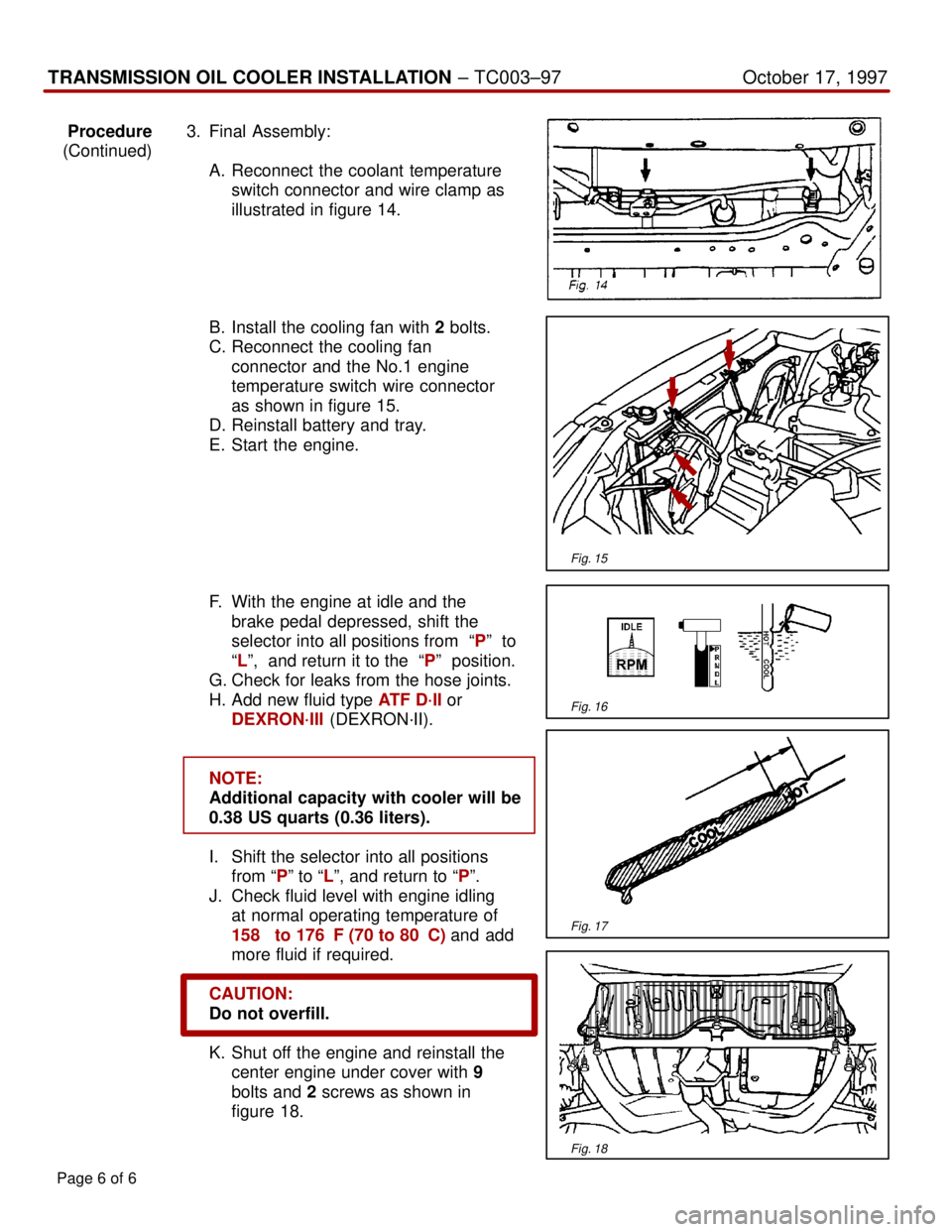
A. Reconnect the coolant temperature
switch connector and wire clamp as
illustrated in figure 14.
B. Install the cooling fan with 2 bolts.
C. Reconnect the cooling fan
connector and the No.1 engine
temperature switch wire connector
as shown in figure 15.
D. Reinstall battery and tray.
E. Start the engine.
F. With the engine at idle and the
brake pedal depressed, shift the
selector into all positions from ªPº to
ªLº, and return it to the ªPº position.
G. Check for leaks from the hose joints.
H. Add new fluid type ATF D´II or
DEXRON´III (DEXRON´II).
NOTE:
Additional capacity with cooler will be
0.38 US quarts (0.36 liters).
I. Shift the selector into all positions
from ªPº to ªLº, and return to ªPº.
J. Check fluid level with engine idling
at normal operating temperature of
158� to 176�F (70 to 80�C) and add
more fluid if required.
CAUTION:
Do not overfill.
K. Shut off the engine and reinstall the
center engine under cover with 9
bolts and 2 screws as shown in
figure 18.
Page 6 of 6
Fig. 15
Fig. 16
Fig. 17
Fig. 18
Page 4002 of 4592

Toyota Supports ASE CertificationPage 1 of 3
EG008-04Title:
M.I.L. ON" 1MZ-FE ENGINE MISFIRE
DTC P0300, P0301, P0302, P0303,
P0304, P0305 OR P0306
Models:
Applicable Avalon, Camry, Sienna & Solara
Technical Service
BULLETIN
April 28, 2004
Some vehicles equipped with 1MZ±FE (V6) engines without VVTi may exhibit a rough
idle and/or a M.I.L. ªONº condition with a diagnostic trouble code or codes for misfire
caused by an improperly operating ignition coil assembly. Production changes have been
implemented to prevent this condition from occuring.
�2001 model year Japan built Camry vehicles equipped with 1MZ±FE engines (V6).
�1998±2001 model year North American built Camry vehicles equipped with
1MZ±FE engines (V6)
�1998 ± 1999 model year Avalon vehicles.
�1998 ± 2000 model year Sienna vehicles.
�1999 ± 2002 model year Solara vehicles equipped with 1MZ±FE engines produced
BEFORE the Production Change Effective VIN shown below.
MODELENGINEPRODUCTION CHANGE EFFECTIVE VIN
Solara1MZ±FE2T1CF2#P*2C578710
OP CODEMODELDESCRIPTIONTIMEOFPT1T2
191011AvalonR & R Ignition Coil (one coil)0.290080±190120273
191011
Camry
SolaraR & R Ignition Coil (one coil)0390080 190120273191011Solara
SiennaR & R Ignition Coil (one coil)0.390080±190120273
Applicable Warranty*:
This repair is covered under the Toyota Federal Emissions Warranty. This warranty is
in effect for 36 months or 36,000 miles, whichever occurs first, from the vehicle's
in-service date.
For California specification vehicles registered and operated in California, Maine,
Massachusetts or Vermont, this repair is covered under the California Emissions
Warranty, which is in effect for 36 months or 50,000 miles, whichever occurs first, from
the vehicle's in-service date.
* Warranty application is limited to correction of a problem based upon a customer's specific complaint.
ENGINE
Introduction
Applicable
Vehicles
Production
Change
Information
Warranty
Information
Page 4003 of 4592

M.I.L. ªONº 1MZ±FE ENGINE MISFIRE DTC P0300 ± P0306 ± EG008-04April 28, 2004
Page 2 of 3
PREVIOUS PART NUMBERCURRENT PART NUMBERPART NAMEQTY
90080±19012SameIgnition Coil Assembly1
SPECIAL SERVICE TOOLS (SSTs)PART NUMBERQUANTITY
Toyota Diagnostic Tester Kit*
010012711
12 Megabyte Diagnostic Tester Program Card
with version 10.2a Software (or later)*01002593-0051
* Essential SSTs.
NOTE:
Additional Diagnostic Tester Kits, Program Cards or other SSTs may be ordered by
calling SPX/OTC at 1-800-933-8335.
TOOLS & MATERIALQUANTITY
Digital Volt Ohmmeter (DVOM)1
1. Confirm if vehicle is currently misfiring, running rough or hesitating.
If YES ± Go to Step 2.
If NO ± Review Freeze Frame Data and attempt to operate vehicle under similar
driving conditions ± see notes below for information that makes it more likely to
duplicate misfire.
NOTE:
The following activities will turn off misfire detection:
�Changing engine RPM greater than 150 RPM.
�Changing throttle position quickly.
Misfire duplication can be duplicated most readily when the engine speed and throttle
angle are held nearly constant for at least 2 minutes.
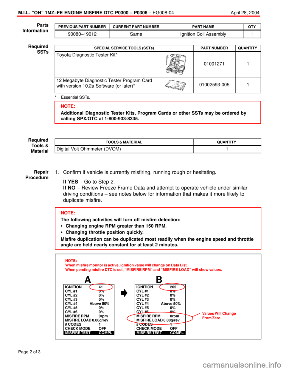
A
IGNITION 41
CYL #1 0%
CYL #2 0%
CYL #3 0%
CYL #4 Above 50%
CYL #5 0%
CYL #6 0%
MISFIRE RPM 0rpm
MISFIRE LOAD 0.00g/rev
# CODES 1
CHECK MODE OFF
MISFIRE TEST COMPL
B
IGNITION 205
CYL #1 0%
CYL #2 0%
CYL #3 0%
CYL #4 Above 50%
CYL #5 0%
CYL #6 0%
MISFIRE RPM 0rpm
MISFIRE LOAD 0.00g/rev
# CODES 1
CHECK MODE OFF
MISFIRE TEST COMPL
NOTE:
When misfire monitor is active, ignition value will change on Data List.
When pending misfire DTC is set, ªMISFIRE RPMº and ªMISFIRE LOADº will show values.
Values Will Change
From Zero
Parts
Information
Required
SSTs
Required
Tools &
Material
Repair
Procedure
Page 4004 of 4592

M.I.L. ªONº 1MZ±FE ENGINE MISFIRE DTC P0300 ± P0306 ± EG008-04April 28, 2004
Page 3 of 3
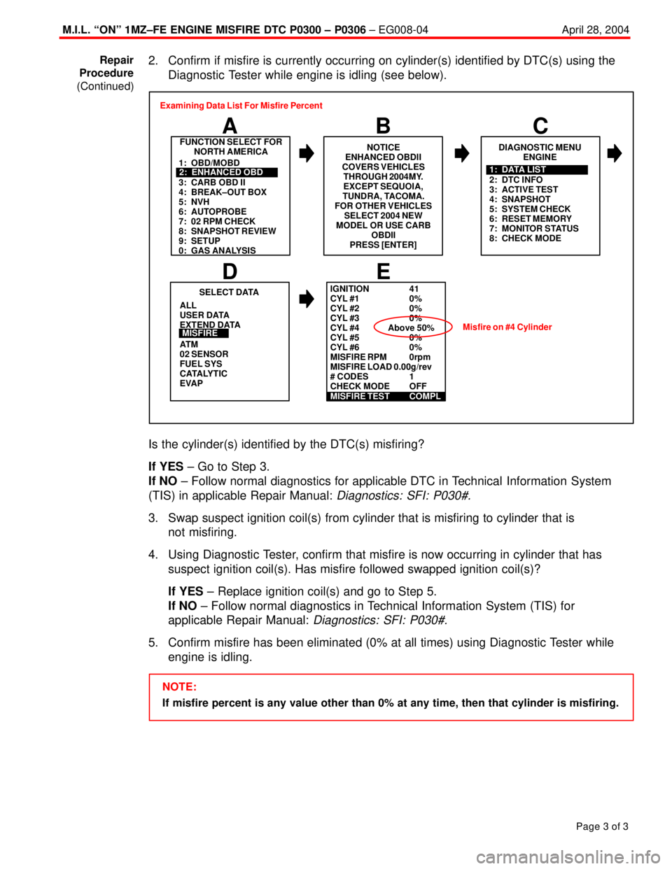
2. Confirm if misfire is currently occurring on cylinder(s) identified by DTC(s) using the
Diagnostic Tester while engine is idling (see below).
FUNCTION SELECT FOR
NORTH AMERICA
B A
DIAGNOSTIC MENU
ENGINE
C
ALL
USER DATA
EXTEND DATA
AT M
02 SENSOR
FUEL SYS
CATALYTIC
EVAP
E
SELECT DATA
D
MISFIRE
1: OBD/MOBD
3: CARB OBD II
4: BREAK±OUT BOX
5: NVH
6: AUTOPROBE
7: 02 RPM CHECK
8: SNAPSHOT REVIEW
9: SETUP
0: GAS ANALYSIS2: ENHANCED OBD
2: DTC INFO
3: ACTIVE TEST
4: SNAPSHOT
5: SYSTEM CHECK
6: RESET MEMORY
7: MONITOR STATUS
8: CHECK MODE1: DATA LIST Examining Data List For Misfire Percent
NOTICE
ENHANCED OBDII
COVERS VEHICLES
THROUGH 2004MY.
EXCEPT SEQUOIA,
TUNDRA, TACOMA.
FOR OTHER VEHICLES
SELECT 2004 NEW
MODEL OR USE CARB
OBDII
PRESS [ENTER]
IGNITION 41
CYL #1 0%
CYL #2 0%
CYL #3 0%
CYL #4 Above 50%
CYL #5 0%
CYL #6 0%
MISFIRE RPM 0rpm
MISFIRE LOAD 0.00g/rev
# CODES 1
CHECK MODE OFF
MISFIRE TEST COMPL
Misfire on #4 Cylinder
Is the cylinder(s) identified by the DTC(s) misfiring?
If YES ± Go to Step 3.
If NO ± Follow normal diagnostics for applicable DTC in Technical Information System
(TIS) in applicable Repair Manual:
Diagnostics: SFI: P030#.
3. Swap suspect ignition coil(s) from cylinder that is misfiring to cylinder that is
not misfiring.
4. Using Diagnostic Tester, confirm that misfire is now occurring in cylinder that has
suspect ignition coil(s). Has misfire followed swapped ignition coil(s)?
If YES ± Replace ignition coil(s) and go to Step 5.
If NO ± Follow normal diagnostics in Technical Information System (TIS) for
applicable Repair Manual:
Diagnostics: SFI: P030#.
5. Confirm misfire has been eliminated (0% at all times) using Diagnostic Tester while
engine is idling.
NOTE:
If misfire percent is any value other than 0% at any time, then that cylinder is misfiring. Repair
Procedure
(Continued)
Page 4020 of 4592
![TOYOTA CAMRY 1999 Service Repair Manual B
[A]: Part Code
[B]: Part Name
[C]: Part Number
Toyota Part Number are indicated.
Not all of the above part numbers of the connector are established for the supply. In case of ordering a connector
or TOYOTA CAMRY 1999 Service Repair Manual B
[A]: Part Code
[B]: Part Name
[C]: Part Number
Toyota Part Number are indicated.
Not all of the above part numbers of the connector are established for the supply. In case of ordering a connector
or](/manual-img/14/57448/w960_57448-4019.png)
B
[A]: Part Code
[B]: Part Name
[C]: Part Number
Toyota Part Number are indicated.
Not all of the above part numbers of the connector are established for the supply. In case of ordering a connector
or terminal with wire, please confirm in advance if there is supply for it using
ªParts Catalog Newsº (published by
Parts Engineering Administration Dept.).
A 5�� ��
90980±11194
L PART NUMBER OF CONNECTORS
Code Part Name Part NumberCode Part NamePart Number
A 1
A 2
A 4
A 6
A 7A/C Ambient Temp. Sensor
A/C Condenser Fan Motor
A/C Triple Pressure SW (A/C Dual and
Single Pressure SW)
A/T Oil Temp. Sensor
ABS Actuator
ABS Actuator90980±11070
90980±11237
90980±10943
90980±11413
90980±11151D 4
D 5
D 6
D 7
D 8
D 9
D10
D11Diode (Door Courtesy Light)
Diode (Key Off Operation)
Diode (Luggage Compartment Light)
Door Lock Control Relay
Door Courtesy Light LH
Door Courtesy Light RH
Door Courtesy SW LH
Door Courtesy SW RH90980±11608
90980±10962
90980±11608
90980±10848
90980±11148
90980±11097
A 8ABS Speed Sensor Front LH
90980±10941
A 9ABS Speed Sensor Front RH
90980±11856 A10Airbag Sensor Front LH
A11Airbag Sensor Front RHD12Door Courtesy SW Front LH
90980±11156 D13Door Courtesy SW Front RH
D14Door Courtesy SW Rear LH
Door Courtesy SW Rear RH
D15
[B]�� ��[C]
A12
Auto Antenna Motor90980±11194 A 3
A/C Condenser Fan Relay90980±10940
[A]
90980±11009
90980±11002
D16
D17Door Key Lock and Unlock SW LH
Door Key Lock and Unlock SW RH90980±11170