Page 4038 of 4592
G
Position of Parts in Engine Compartment
I 1 Idle Air Control Valve
I 2 Ignition Coil and Igniter No.1
I 3 Ignition Coil and Igniter No.2
I 4 Injector No.1
I 5 Injector No.2
I 6 Injector No.3
I 7 Injector No.4
I 8 Intake Air Temp. Sensor
M 1 Manifold Absolute Pressure Sensor
N 1 Noise Filter (Ignition)
O 1 Oil Pressure SW
P 1 Park/Neutral Position SW,A/T Indicator Light SW and
Back±Up Light SW
P 2 Power Steering Oil Pressure SWR 1 Radiator Fan Motor
S 1 Starter
S 2 Starter
T 1 Throttle Position Sensor
V 1 Vehicle Speed Sensor (Combination Meter)
V 2 VSV (EGR)
W 1 Washer Level Warning SW
W 2 Washer Motor
W 3 Water Temp. Sender
W 4 Water Temp. SW No.1
Page 4056 of 4592
B±R
NSWA 6C20 C3C19
A 11IGT1 IGF IGT2
STAI 4A A
EC
BRBR BRY±R W±RBR W±RB
W±R
IGT IGF GND IGF IGT GND+B +B
A
B±W
CC
1
GR
B±R
B±R
B±RB±W
IGNITION COIL
AND IGNITER
NO. 2 IGNITION COIL
AND IGNITER
NO. 1JUNCTION CONNECTOR
NOISE FILTER
(
IGNITION)
JUNCTION
CONNECTOR J19
I 2 I 3
J18
N 1
E 4
ENGINE CONTROL MODULEC A, E 6 CC
23432411
W±R
Page 4062 of 4592
P
N5
6
I 4
EC
5A STARTER
1K 4
B B
A 14 C3 C 20 C19 A 12A B
A 1A6A11 1J 3
4 1 4 1
A2 3 3 2B
B±Y B±Y
B± W
B±Y
Y±R W± R W±RBB±Y
B±WB±Y
B±Y
B±W
GR GR GR BR B±RBRG± R
W±R
BPARK/NEUTRAL
POSITION SW
JUNCTION
CONNECTOR J22P 1
JUNCTION
CONNECTOR
IGNITION COIL AND
IGNITER NO. 1
IGNITION COIL AND
IGNITER NO. 2
J18
I 2
I 3
A A
BRB±R
IG2 10 IG2 11
E 3B±Y
CC
C JUNCTION
CONNECTOR J19 IGTIGFIGFIGT
+B GND GND+B
IG312
B±RL±B
IG3 9
A EEAABB B±Y
J23
JUNCTION
CONNECTORB A, J24
E 4
ENGINE CONTROL MODULEB A, E 5 C, E 6 D, E 7A BB C
J 6
JUNCTION
CONNECTORB A, J 7
B±W
B±W
B±W
D 1
C 26
A A 22
W± BBR W± B R
B±Y
B±Y
L±B
LG±B
G± R
B±R
BR
BR B±R
BR BRE05 IGT2 IGF IGT1 +B1 FCTHCNG1 +B BATT NSW STA
B±R B±YB±W
Page 4064 of 4592
FROM POWER SOURCE SYSTEM (
SEE PAGE 44)
1C 91J11
1 2
2 1
IJ2 7
IJ2 9IG3 10 IG2 1
1 I 4 I 4
A 10 A 15A 21 D10 C18 B 10B 12 B 15 C4C17 C5D3
2 1B 8
2 A
B 12 3
A
1 3
2 5 1
BR
B±YBR B±Y
BR
BR
BR
B±Y TE1
B± LL±R L±W BR
W± L W±L W± LG L±Y
G L±Y R±BR±B R±W
R±BL±W
B± R
BR
L
B±W
G± O G± O
B±YB±Y
BR
E1 +B
10A TAIL
10A
MIRROR±
HEATER (
SHIELDED)
(
SHIELDED) L
B±R
DIODE
(
IDLE±UP)
DATA LINK
CONNECTOR 1
CRANKSHAFT
POSITION SENSOR
CAMSHAFT
POSITION SENSOR
JUNCTION
CONNECTORD 1
C 2
C 1
J12
D 6
JUNCTION CONNECTOR
A/C SWHEATER CONTROL SW
POWER STEERING OIL PRESSURE SWFROM MG
CLT RELAY
FROM
A/C DUAL
PRESSURE SW
TO A/C
MAGNETIC
CLUTCH AND
LOCK SENSORJ12
P 2 H 7
A12
BR
ENGINE CONTROL MODULEB E 4 E 5ACE 6 , , D, E 7
IG1 8D 12
LL JUNCTION
CONNECTOR J 8
C 5
CENTER AIRBAG
SENSOR ASSEMBLYIG1 9
B± R
A A
4
L
TE1 NE NE± G EL S
LOCK A/CS F/PS MGC PRS LOCK IN THRPSW
A/C EVAPORATOR
TEMP. SENSOR A11
B
IG1 1
Page 4149 of 4592

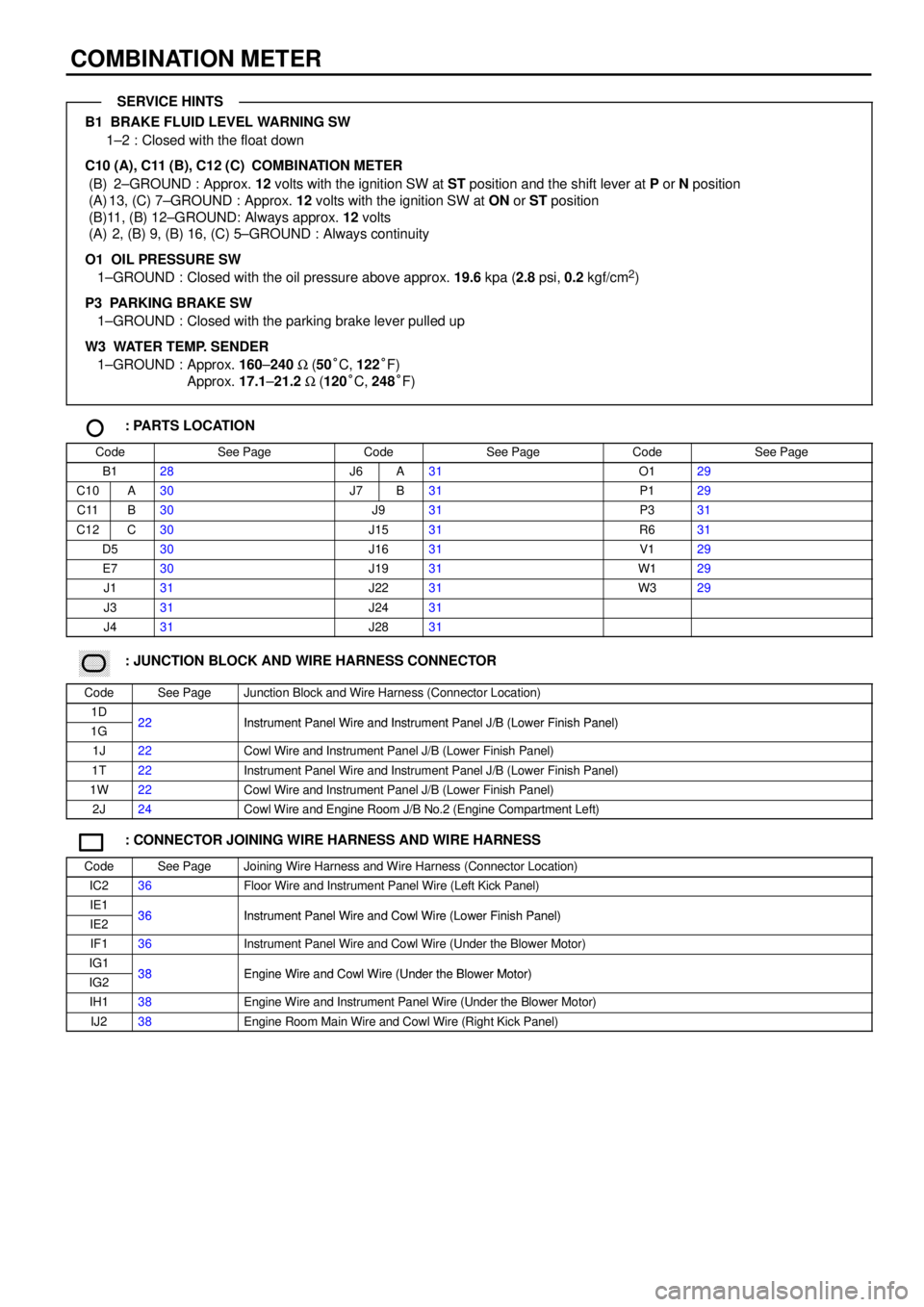
COMBINATION METER
B1 BRAKE FLUID LEVEL WARNING SW
1±2 : Closed with the float down
C10 (A), C11 (B), C12 (C)
COMBINATION METER
(B) 2±GROUND : Approx. 12 volts with the ignition SW at ST position and the shift lever at P or N position
(A) 13, (C) 7±GROUND : Approx. 12 volts with the ignition SW at ON or ST position
(B)11, (B) 12±GROUND: Always approx. 12 volts
(A) 2, (B) 9, (B) 16, (C) 5±GROUND : Always continuity
O1 OIL PRESSURE SW
1±GROUND : Closed with the oil pressure above approx. 19.6 kpa (2.8 psi, 0.2 kgf/cm
2)
P3 PARKING BRAKE SW
1±GROUND : Closed with the parking brake lever pulled up
W3 WATER TEMP. SENDER
1±GROUND : Approx. 160±240 W (50°C, 122°F)
Approx. 17.1±21.2 W (120°C, 248°F)
: PARTS LOCATION
CodeSee PageCodeSee PageCodeSee Page
B128J6A31O129
C10A30J7B31P129
C11B30J931P331
C12C30J1531R631
D530J1631V129
E730J1931W129
J131J2231W329
J331J2431
J431J2831
������ ���: JUNCTION BLOCK AND WIRE HARNESS CONNECTOR
CodeSee PageJunction Block and Wire Harness (Connector Location)
1D22Instrument Panel Wire and Instrument Panel J/B (Lower Finish Panel)1G22Instrument Panel Wire and Instrument Panel J/B (Lower Finish Panel)
1J22Cowl Wire and Instrument Panel J/B (Lower Finish Panel)
1T22Instrument Panel Wire and Instrument Panel J/B (Lower Finish Panel)
1W22Cowl Wire and Instrument Panel J/B (Lower Finish Panel)
2J24Cowl Wire and Engine Room J/B No.2 (Engine Compartment Left)
: CONNECTOR JOINING WIRE HARNESS AND WIRE HARNESS
CodeSee PageJoining Wire Harness and Wire Harness (Connector Location)
IC236Floor Wire and Instrument Panel Wire (Left Kick Panel)
IE136Instrument Panel Wire and Cowl Wire (Lower Finish Panel)IE236Instrument Panel Wire and Cowl Wire (Lower Finish Panel)
IF136Instrument Panel Wire and Cowl Wire (Under the Blower Motor)
IG138Engine Wire and Cowl Wire (Under the Blower Motor)IG238Engine Wire and Cowl Wire (Under the Blower Motor)
IH138Engine Wire and Instrument Panel Wire (Under the Blower Motor)
IJ238Engine Room Main Wire and Cowl Wire (Right Kick Panel)
SERVICE HINTS
Page 4152 of 4592

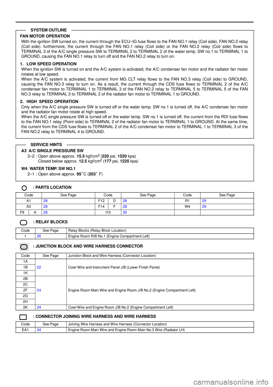
FAN MOTOR OPERATION
With the ignition SW turned on, the current through the ECU±IG fuse flows to the FAN NO.1 relay (Coil side), FAN NO.2 relay
(Coil side). furthermore, the current through the FAN NO.1 relay (Coil side) or the FAN NO.2 relay (Coil side) flows to
TERMINAL 3 of the A/C single pressure SW to TERMINAL 2 to TERMINAL 2 of the water temp. SW no.1 to TERMINAL 1 to
GROUND, causing the FAN NO.1 relay to turn off and the FAN NO.2 relay to turn on.
1. LOW SPEED OPERATION
When the ignition SW is turned on and the A/C system is activated, the A/C condenser fan motor and the radiator fan motor
rotates at low speed.
When the A/C system is activated, the current from MG CLT relay flows to the FAN NO.3 relay (Coil side) to GROUND,
causing the FAN NO.3 relay to turn on. As a result, the current through the CDS fuse flows to TERMINAL 2 of the A/C
condenser fan motor to TERMINAL 1 to TERMINAL 3 of the FAN NO.2 relay to TERMINAL 5 to TERMINAL 5 of the FAN
NO.3 relay to TERMINAL 3 to TERMINAL 2 of the radiator fan motor to TERMINAL 1 to GROUND.
2. HIGH SPEED OPERATION
Only when the A/C single pressure SW is turned off or the water temp. SW no.1 is turned off, the A/C condenser fan motor
and the radiator fan motor rotate at high speed.
When the A/C single pressure SW is turned off or the water temp. SW no.1 is turned off. the current from the RDI fuse flows
to the FAN NO.1 relay (Point side) to TERMINAL 2 of the radiator fan motor to TERMINAL 1 to GROUND. At the same time,
the current from the CDS fuse flows to TERMINAL 2 of the A/C condenser fan motor to TERMINAL 1 to TERMINAL 3 of the
FAN NO.2 relay to TERMINAL 4 to GROUND.
A3 A/C SINGLE PRESSURE SW
3±2 : Open above approx. 15.5 kgf/cm2
(220 psi, 1520 kpa)
Closed below approx. 12.5 kgf/cm2 (177 psi, 1225 kpa)
W4 WATER TEMP. SW NO.1
2±1 : Open above approx. 95°C (203° F)
: PARTS LOCATION
CodeSee PageCodeSee PageCodeSee Page
A128F12D28R129
A328F14F28W429
F9A28I1030
: RELAY BLOCKS
CodeSee PageRelay Blocks (Relay Block Location)
126Engine Room R/B No.1 (Engine Compartment Left)
������ ���: JUNCTION BLOCK AND WIRE HARNESS CONNECTOR
CodeSee PageJunction Block and Wire Harness (Connector Location)
1A
1B22Cowl Wire and Instrument Panel J/B (Lower Finish Panel)
1K
()
2B
2C
2F24Engine Room Main Wire and Engine Room J/B No.2 (Engine Compartment Left)
2G
gg(g)
2H
2K24Cowl Wire and Engine Room J/B No.2 (Engine Compartment Left)
: CONNECTOR JOINING WIRE HARNESS AND WIRE HARNESS
CodeSee PageJoining Wire Harness and Wire Harness (Connector Location)
EA134Engine Room Main Wire and Engine Room Main No.3 Wire (Radiator LH)
SYSTEM OUTLINE
SERVICE HINTS
Page 4158 of 4592

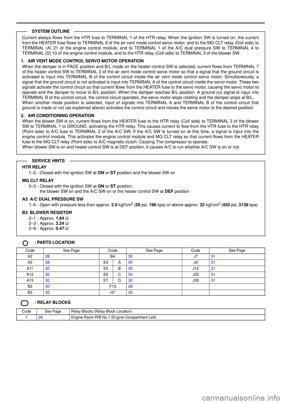
Current always flows from the HTR fuse to TERMINAL 1 of the HTR relay. When the ignition SW is turned on, the current
from the HEATER fuse flows to TERMINAL 6 of the air vent mode control servo motor, and to the MG CLT relay (Coil side) to
TERMINAL (A) 21 of the engine control module, and to TERMINAL 1 of the A/C dual pressure SW to TERMINAL 4 to
TERMINAL (D) 10 of the engine control module, and to the HTR relay (Coil side) to TERMINAL 3 of the blower SW.
1. AIR VENT MODE CONTROL SERVO MOTOR OPERATION
When the damper is in FACE position and B/L mode on the heater control SW is selected, current flows from TERMINAL 7
of the heater control SW to TERMINAL 2 of the air vent mode control serve motor so that a signal that the ground circuit is
activated is input into TERMINAL B of the control circuit inside the air vent mode control servo motor. Simultaneously, a
signal that the ground circuit is not activated is input into TERMINAL A of the control circuit inside the servo motor. These two
signals activate the control circuit so that current flows from the HEATER fuse to the servo motor, causing the servo motor to
operate and the damper to move to B/L position. When the damper reaches B/L position. A ground cut signal is input into
TERMINAL B of the control circuit, the control circuit operates, the servo motor stops rotating and the damper stops at B/L.
When another mode position is selected, input of signals into TERMINAL A and TERMINAL B of the control circuit that
ground is made or not (as explained above) activates the control circuit and moves the serve motor to the desired position.
2. AIR CONDITIONING OPERATION
When the blower SW is on, current flows from the HEATER fuse to the HTR relay (Coil side) to TERMINAL 3 of the blower
SW to TERMINAL 1 to GROUND, activating the HTR relay. This causes current to flow from the HTR fuse to the HTR relay
(Point side) to A/C fuse to TERMINAL 2 of the A/C SW. If the A/C SW is turned on at this time, a signal is input into the
engine control module. This activates the engine control module and MG CLT relay so that current flows from the HEATER
fuse to the MG CLT relay (Point side) to A/C magnetic clutch. Causing The compressor to operate.
When blower SW is on and heater control SW is at DEF position, it causes A/C to run whether A/C SW is on or not.
HTR RELAY
1±2 : Closed with the ignition SW at ON or ST position and the blower SW on
MG CLT RELAY
5±3 : Closed with the ignition SW at ON or ST position,
the blower SW on and the A/C SW on or the heater control SW at DEF position
A3 A/C DUAL PRESSURE SW
1±4 : Open with pressure less than approx. 2.0 kgf/cm
2 (28 psi, 196 kpa) or above approx. 32 kgf/cm2 (455 psi, 3138 kpa)
B3
BLOWER RESISTOR
2±1 : Approx. 1.64 W
2±3 : Approx. 3.24 W
2±6 : Approx. 0.47 W
: PARTS LOCATION
CodeSee PageCodeSee PageCodeSee Page
A228B430J731
A328E4A30J931
A1130E5B30J1231
A1230E6C30J2031
A1530E7D30J3031
B230F1328
B330H730
: RELAY BLOCKS
CodeSee PageRelay Blocks (Relay Block Location)
126Engine Room R/B No.1 (Engine Compartment Left)
SYSTEM OUTLINE
SERVICE HINTS
Page 4162 of 4592
(
E04)
(
E01)
(
E02)
(
E03)
HEATED OXYGEN
SENSOR
A/C MAGNETIC
CLUTCH AND
LOCK SENSOR COMBINATION
METER
IGNITION COIL AND
IGNITER NO. 1
IGNITION COIL AND
IGNITER NO. 2
DATA LINK
CONNECTOR 1
DATA LINK
CONNECTOR 2
DATA LINK
CONNECTOR 3ENGINE
CONTROL
MODULE IH13
A
A
EC A
EC
I 4 IG212
B B
B B A C
A CIG36
IJ210AA
A BR
BR
BR
BRBR
BR
BR
BR
BR BR
BR BR
BR BR BR BR
BR
BR BRBR
BR
A
JUNCTION
CONNECTOR J18
(
ET)
(
SG)
J 6
JUNCTION
CONNECTORB A, J 7(
E1) IG13
ENGINE CONTROL
MODULEBR A IDLE AIR
CONTROL VALVEW±B
W± B
BR
JUNCTION
CONNECTOR J20
(
ES)
W±B W±B
BRBR
W± B W±B
BL IJ 6
BB1 B 2IG
DOOR LOCK MOTOR
AND DOOR UNLOCK
DETECTION SW
REAR RH RADIO AND PLAYERCOMBINATION
METER (
E05)