Page 3524 of 4592
SR06N±03
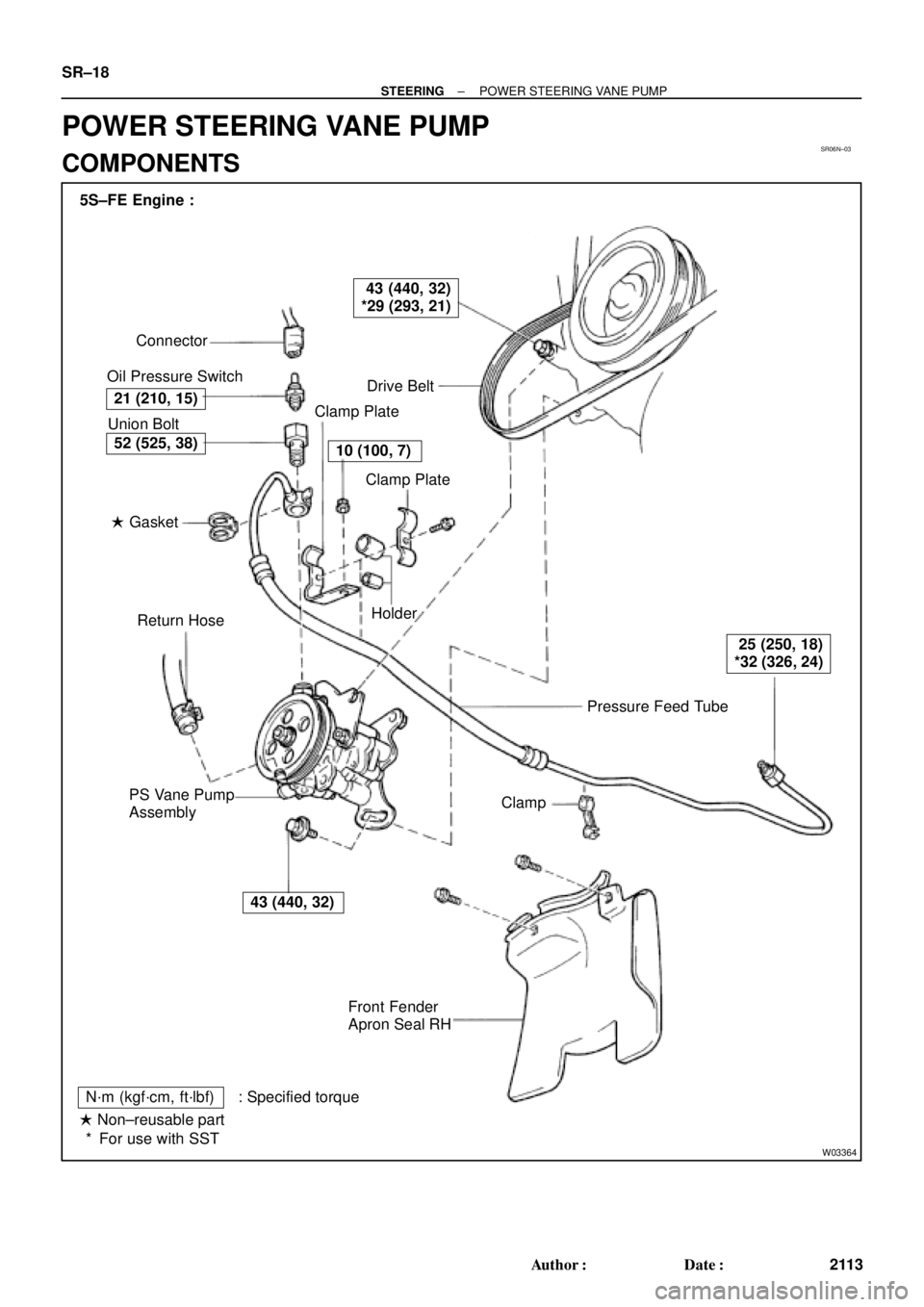
W03364
Pressure Feed Tube Connector
Oil Pressure Switch
Drive Belt
Clamp Plate
Clamp Plate
Holder
Clamp
Front Fender
Apron Seal RH PS Vane Pump
AssemblyReturn Hose � Gasket Union Bolt 5S±FE Engine :
21 (210, 15)
43 (440, 32)
*29 (293, 21)
10 (100, 7)
25 (250, 18)
*32 (326, 24)
43 (440, 32)
52 (525, 38)
N´m (kgf´cm, ft´lbf) : Specified torque
� Non±reusable part
For use with SST * SR±18
± STEERINGPOWER STEERING VANE PUMP
2113 Author�: Date�:
POWER STEERING VANE PUMP
COMPONENTS
Page 3525 of 4592
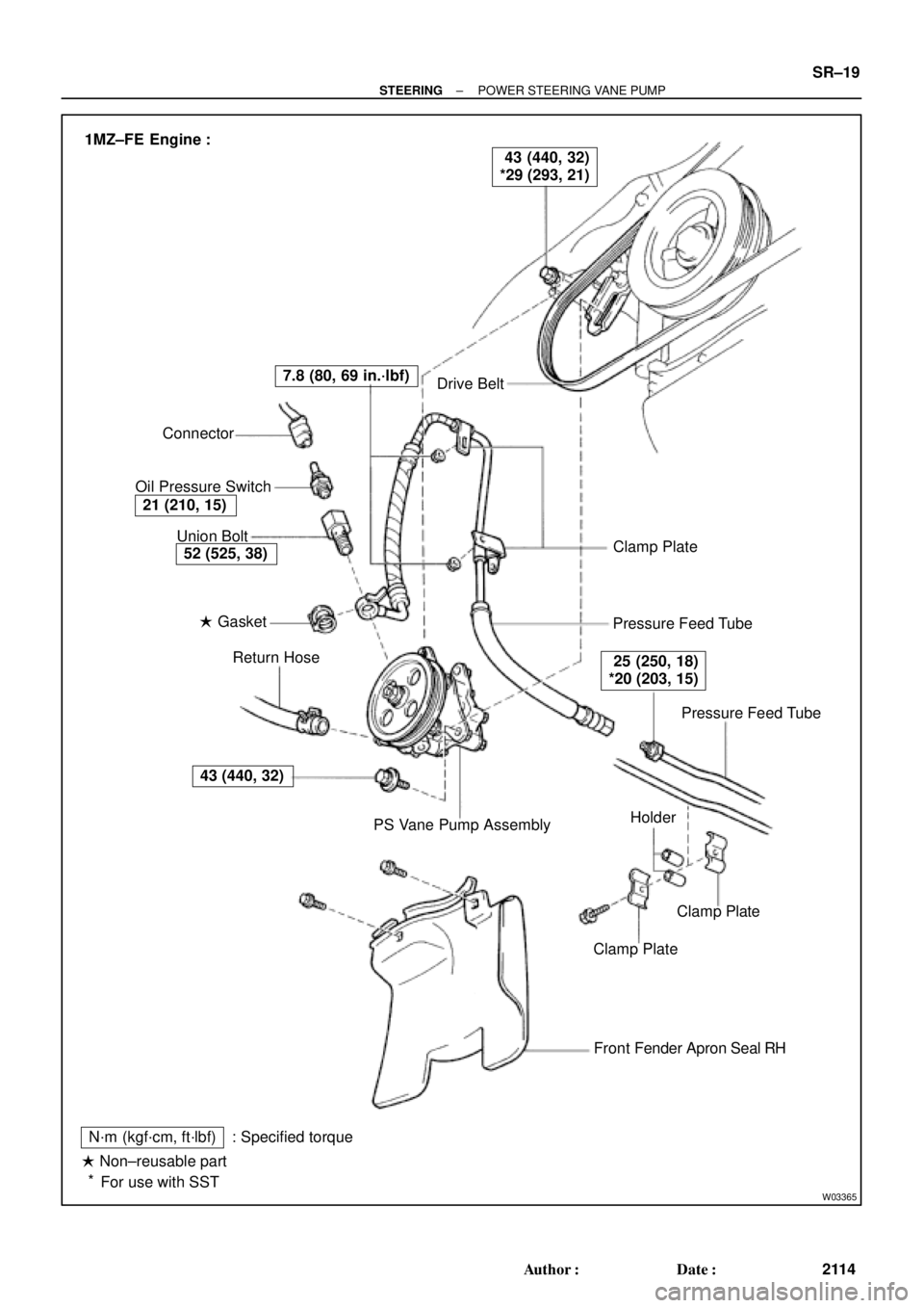
W03365
Drive Belt
Clamp Plate
Pressure Feed Tube
Pressure Feed Tube
Clamp Plate
Clamp Plate
Front Fender Apron Seal RH
N´m (kgf´cm, ft´lbf)
� Non±reusable part
For use with SST: Specified torquePS Vane Pump Assembly Return Hose � Gasket Union Bolt Connector
Oil Pressure Switch
43 (440, 32)
52 (525, 38)
21 (210, 15)
7.8 (80, 69 in.´lbf)
25 (250, 18)
*20 (203, 15)
43 (440, 32)
*29 (293, 21) 1MZ±FE Engine :
Holder
*
± STEERINGPOWER STEERING VANE PUMP
SR±19
2114 Author�: Date�:
Page 3526 of 4592
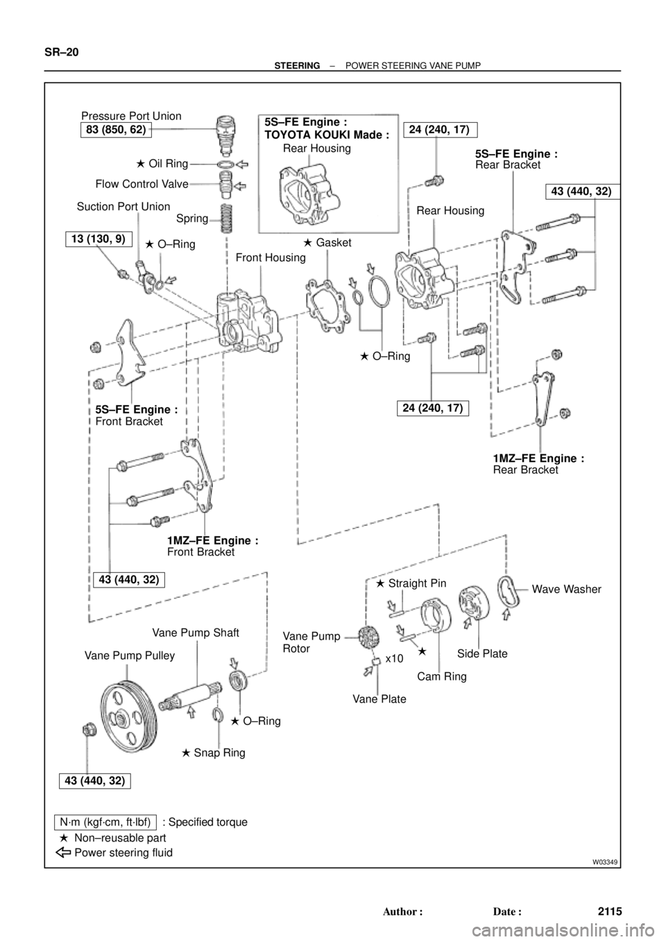
W03349
Pressure Port Union
� Oil Ring
Flow Control Valve
Suction Port Union
Spring
� O±Ring
Front Housing� Gasket Rear Housing
Rear Bracket
Rear Housing
� O±Ring
Rear Bracket
Wave Washer
�
Cam Ring � Straight Pin
Vane Plate Rotor
Side Plate Vane Pump
x10
� O±Ring
� Snap Ring
N´m (kgf´cm, ft´lbf)
Non±reusable part
Power steering fluid: Specified torque Vane Pump Shaft
Vane Pump PulleyFront Bracket Front Bracket
�
5S±FE Engine :
TOYOTA KOUKI Made :24 (240, 17)
43 (440, 32)
24 (240, 17)
83 (850, 62)
13 (130, 9)
5S±FE Engine :5S±FE Engine :
1MZ±FE Engine :1MZ±FE Engine :
43 (440, 32)
43 (440, 32) SR±20
± STEERINGPOWER STEERING VANE PUMP
2115 Author�: Date�:
Page 3527 of 4592

SR06O±01
W04220
5S±FE Engine :
1MZ±FE Engine :
Pressure
Feed TubeSST SST
W03360
Example 5S±FE Engine :
A
B
± STEERINGPOWER STEERING VANE PUMP
SR±21
2116 Author�: Date�:
REMOVAL
1. REMOVE FRONT FENDER APRON SEAL RH
Remove the 2 bolts.
2. DISCONNECT RETURN HOSE
NOTICE:
Take care not to spill fluid on the drive belt.
3. DISCONNECT PRESSURE FEED TUBE
(a) 5S±FE Engine:
Remove the clamp plate set bolt and nut.
(b) 5S±FE Engine:
Remove the 2 clamp plates and 2 holders from the tube.
(c) 5S±FE Engine:
Remove the clamp from the tube.
(d) 1MZ±FE Engine:
Remove the 2 clamp plate set nuts.
(e) 1MZ±FE Engine:
Remove the bolt.
(f) 1MZ±FE Engine:
Remove the 2 clamp plates and 2 holders from the tube.
(g) 5S±FE and 1MZ±FE Engines:
Using SST, disconnect the tube.
SST 09631±22020
4. REMOVE DRIVE BELT
Loosen the 2 (A and B) bolts.
5. REMOVE PS VANE PUMP ASSEMBLY WITH PRES-
SURE FEED TUBE
(a) Disconnect the connector from the oil pressure switch.
(b) Loosen bolt A sufficiently so that pump assembly can be
removed.
HINT:
Bolt A cannot be removed.
6. REMOVE PRESSURE FEED TUBE
(a) Remove the oil pressure switch from the union bolt.
NOTICE:
Be careful not to drop the switch.
If the switch is dropped or strongly damaged, replace it with a
new one.
(b) Remove the union bolt and gasket.
Page 3529 of 4592

SR06Q±01
R15196
Caliper Gauge
Micrometer
Vane Pump Shaft
Bushing
Front Housing
N00372
Thickness
Height
Length
R10282
Feeler Gauge
± STEERINGPOWER STEERING VANE PUMP
SR±23
2118 Author�: Date�:
INSPECTION
NOTICE:
When using a vise, do not overtighten it.
1. CHECK OIL CLEARANCE BETWEEN VANE PUMP
SHAFT AND BUSHING
Using a micrometer and caliper gauge, measure the oil clear-
ance.
5S±FE and 1MZ±FE Engines:
Standard clearance:
0.03 ± 0.05 mm (0.0012 ± 0.0020 in.)
Maximum clearance: 0.07 mm (0.0028 in.)
If it is more than the maximum, replace the front housing and
vane pump shaft.
2. INSPECT VANE PUMP ROTOR AND VANE PLATES
(a) Using a micrometer, measure the height, thickness and
length of the plates.
5S±FE and 1MZ±FE Engines:
Minimum height: 8.6 mm (0.339 in.)
Minimum thickness: 1.397 mm (0.0550 in.)
Minimum length: 14.991 mm (0.5902 In.)
(b) Using a feeler gauge, measure the clearance between
the rotor groove and plate.
5S±FE and 1MZ±FE Engines:
Maximum clearance: 0.035 mm (0.0014 in.)
If it is more than the maximum, replace the plate and/or rotor
with one having the same mark stamped on the cam ring.
Page 3531 of 4592
R08702
Calipers
R11290
Vinyl Tape
W03541
Press
SST
Oil Seal
± STEERINGPOWER STEERING VANE PUMP
SR±25
2120 Author�: Date�:
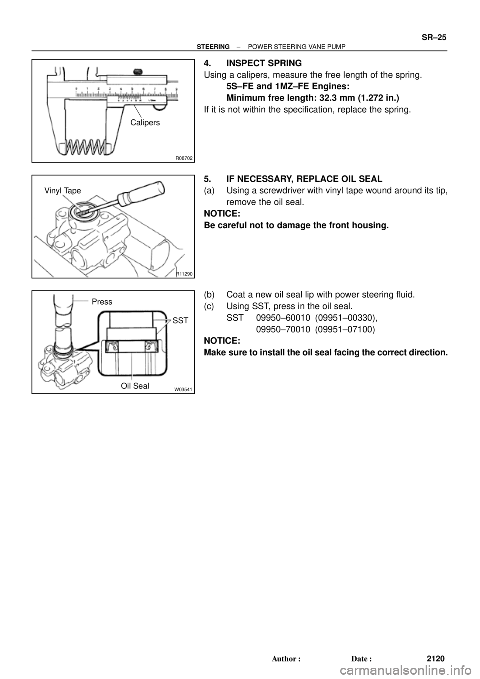
4. INSPECT SPRING
Using a calipers, measure the free length of the spring.
5S±FE and 1MZ±FE Engines:
Minimum free length: 32.3 mm (1.272 in.)
If it is not within the specification, replace the spring.
5. IF NECESSARY, REPLACE OIL SEAL
(a) Using a screwdriver with vinyl tape wound around its tip,
remove the oil seal.
NOTICE:
Be careful not to damage the front housing.
(b) Coat a new oil seal lip with power steering fluid.
(c) Using SST, press in the oil seal.
SST 09950±60010 (09951±00330),
09950±70010 (09951±07100)
NOTICE:
Make sure to install the oil seal facing the correct direction.
Page 3534 of 4592
SR06S±01
W03361
5S±FE Engine :
1MZ±FE Engine :Pressure Feed Tube
Stopper
Pressure
Feed
StopperTube
W03360
Example 5S±FE Engine :
A
B
W03542
5S±FE Engine :
SST
Fulcrum
Length SR±28
± STEERINGPOWER STEERING VANE PUMP
2123 Author�: Date�:
INSTALLATION
1. INSTALL PRESSURE FEED TUBE
(a) Torque the union bolt with a new gasket.
HINT:
Make sure the stopper of the tube is touching the front bracket,
as shown, then torque the union bolt.
5S±FE and 1MZ±FE Engines:
Torque: 52 N´m (525 kgf´cm, 38 ft´lbf)
(b) Install the oil pressure switch to the union bolt.
5S±FE and 1MZ±FE Engines:
Torque: 21 N´m (210 kgf´cm, 15 ft´lbf)
2. INSTALL PS VANE PUMP ASSEMBLY WITH PRESS-
ER FEED TUBE
Temporarily tighten the 2 (A and B) bolts.
3. INSTALL DRIVE BELT
(a) Adjust drive belt tension.
(See page SR±3)
(b) 5S±FE Engine:
Using SST, torque the A bolt.
SST 09249±63010
Torque: 29 N´m (293 kgf´cm, 21 ft´lbf)
HINT:
Use a torque wrench with a fulcrum length of 300 mm (11.81
in.).
Page 3535 of 4592

W03543
1MZ±FE Engine :
Engine Wire Clamp
Fulcrum
Length
SST
W04221
5S±FE Engine :
1MZ±FE Engine :Fulcrum
Length
SST Pressure
Feed Tube
Fulcrum
LengthSST
± STEERINGPOWER STEERING VANE PUMP
SR±29
2124 Author�: Date�:
(c) 1MZ±FE Engine:
Using SST, torque the A bolt.
SST 09249±63010
Torque: 29 N´m (293 kgf´cm, 21 ft´lbf)
HINT:
�Use a torque wrench with a fulcrum length of 300 mm
(11.81 in.).
�Disconnect the clamp with engine wire.
(d) Torque the B bolt.
5S±FE and 1MZ±FE Engines:
Torque: 43 N´m (440 kgf´cm, 32 ft´lbf)
(e) Connect the connector to the oil pressure switch.
NOTICE:
Be careful for oil on the connector.
4. CONNECT PRESSURE FEED TUBE
(a) Using SST, connect the tube.
SST 09631±22020
5S±FE Engine:
Torque: 32 N´m (326 kgf´cm, 24 ft´lbf)
1MZ±FE Engine:
Torque: 20 N´m (203 kgf´cm, 15 ft´lbf)
HINT:
�Use a torque wrench with a fulcrum length of 300 mm
(11.81 in.).
�This torque value is effective in case that SST is parallel
to a torque wrench.
(b) 5S±FE Engine:
Install the clamp to the tube.
(c) 5S±FE Engine:
Install the 2 clamp plates and 2 holders to the tube.
(d) 5S±FE Engine:
Install the clamp plate set bolt.
(e) 5S±FE Engine:
Install the clamp plate set nut.
Torque: 10 N´m (100 kgf´cm, 7 ft´lbf)
(f) 1MZ±FE Engine:
Install the 2 clamp plates and 2 holders to the tube.
(g) 1MZ±FE Engine:
Tighten the bolt.
(h) 1MZ±FE Engine:
Install the 2 clamp plate set nuts.
Torque: 7.8 N´m (80 kgf´cm, 69 in.´lbf)
5. CONNECT RETURN HOSE