Page 3561 of 4592
W03086
F02267
1
2
F01195
Bolt
Adjusting
ValueSet Bolt
15'
30'Adjusting Bolt90105±15001 90105±15004 90105±15005 90105±15006
45'
1°00'
1°15'
1°30'121212121 Dot 2 Dots 3 Dots
± SUSPENSION AND AXLEFRONT WHEEL ALIGNMENT
SA±5
1956 Author�: Date�:
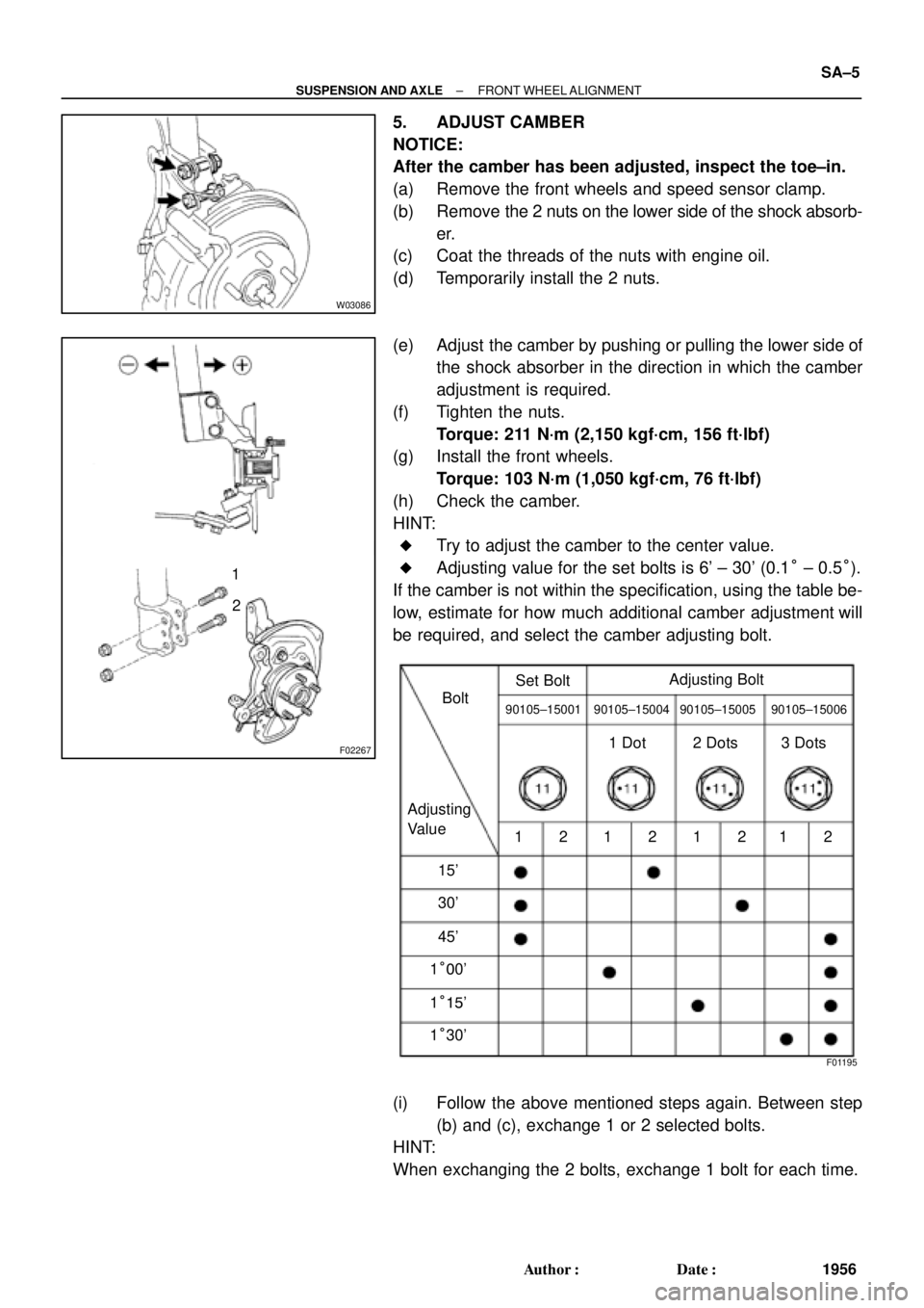
5. ADJUST CAMBER
NOTICE:
After the camber has been adjusted, inspect the toe±in.
(a) Remove the front wheels and speed sensor clamp.
(b) Remove the 2 nuts on the lower side of the shock absorb-
er.
(c) Coat the threads of the nuts with engine oil.
(d) Temporarily install the 2 nuts.
(e) Adjust the camber by pushing or pulling the lower side of
the shock absorber in the direction in which the camber
adjustment is required.
(f) Tighten the nuts.
Torque: 211 N´m (2,150 kgf´cm, 156 ft´lbf)
(g) Install the front wheels.
Torque: 103 N´m (1,050 kgf´cm, 76 ft´lbf)
(h) Check the camber.
HINT:
�Try to adjust the camber to the center value.
�Adjusting value for the set bolts is 6' ± 30' (0.1° ± 0.5°).
If the camber is not within the specification, using the table be-
low, estimate for how much additional camber adjustment will
be required, and select the camber adjusting bolt.
(i) Follow the above mentioned steps again. Between step
(b) and (c), exchange 1 or 2 selected bolts.
HINT:
When exchanging the 2 bolts, exchange 1 bolt for each time.
Page 3590 of 4592
SA07N±01
Z19346
To Outside SA±34
± SUSPENSION AND AXLEFRONT SHOCK ABSORBER
1985 Author�: Date�:
REMOVAL
1. REMOVE FRONT WHEEL
Torque: 103 N´m (1,050 kgf´cm, 76 ft´lbf)
2. REMOVE FLEXIBLE HOSE AND ABS SPEED SEN-
SOR WIRE HARNESS (w/ ABS) AND CLAMP FROM
SHOCK ABSORBER
Remove the bolt, flexible hose and ABS wire harness clamp.
Torque: 29 N´m (300 kgf´cm, 22 ft´lbf)
3. DISCONNECT STABILIZER BAR LINK FROM SHOCK
ABSORBER (See page SA±48)
4. DISCONNECT SHOCK ABSORBER FROM STEERING
KNUCKLE
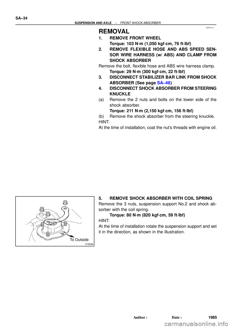
(a) Remove the 2 nuts and bolts on the lower side of the
shock absorber.
Torque: 211 N´m (2,150 kgf´cm, 156 ft´lbf)
(b) Remove the shock absorber from the steering knuckle.
HINT:
At the time of installation, coat the nut's threads with engine oil.
5. REMOVE SHOCK ABSORBER WITH COIL SPRING
Remove the 3 nuts, suspension support No.2 and shock ab-
sorber with the coil spring.
Torque: 80 N´m (820 kgf´cm, 59 ft´lbf)
HINT:
At the time of installation rotate the suspension support and set
it in the direction, as shown in the illustration.
Page 3613 of 4592
SA08A±01
R00749
R10288
W03213
± SUSPENSION AND AXLEREAR SHOCK ABSORBER
SA±57
2008 Author�: Date�:
REMOVAL
1. REMOVE REAR SIDE SEATBACK
(See page BO±113 or BO±118)
2. REMOVE REAR WHEEL
Torque: 103 N´m (1,050 kgf´cm, 76 ft´lbf)
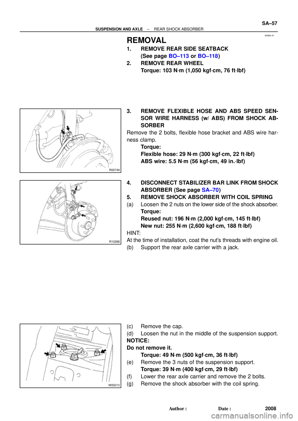
3. REMOVE FLEXIBLE HOSE AND ABS SPEED SEN-
SOR WIRE HARNESS (w/ ABS) FROM SHOCK AB-
SORBER
Remove the 2 bolts, flexible hose bracket and ABS wire har-
ness clamp.
Torque:
Flexible hose: 29 N´m (300 kgf´cm, 22 ft´lbf)
ABS wire: 5.5 N´m (56 kgf´cm, 49 in.´lbf)
4. DISCONNECT STABILIZER BAR LINK FROM SHOCK
ABSORBER (See page SA±70)
5. REMOVE SHOCK ABSORBER WITH COIL SPRING
(a) Loosen the 2 nuts on the lower side of the shock absorber.
Torque:
Reused nut: 196 N´m (2,000 kgf´cm, 145 ft´lbf)
New nut: 255 N´m (2,600 kgf´cm, 188 ft´lbf)
HINT:
At the time of installation, coat the nut's threads with engine oil.
(b) Support the rear axle carrier with a jack.
(c) Remove the cap.
(d) Loosen the nut in the middle of the suspension support.
NOTICE:
Do not remove it.
Torque: 49 N´m (500 kgf´cm, 36 ft´lbf)
(e) Remove the 3 nuts of the suspension support.
Torque: 39 N´m (400 kgf´cm, 29 ft´lbf)
(f) Lower the rear axle carrier and remove the 2 bolts.
(g) Remove the shock absorber with the coil spring.
Page 3630 of 4592
F04031
F04048
1
2
F01195
Bolt
Adjusting
ValueSet Bolt
15'
30'Adjusting Bolt90105±15001 90105±15004 90105±15005 90105±15006
45'
1°00'
1°15'
1°30'121212121 Dot
2 Dots3 Dots SA±2
± SUSPENSION AND AXLEFRONT WHEEL ALIGNMENT
509 Author�: Date�:
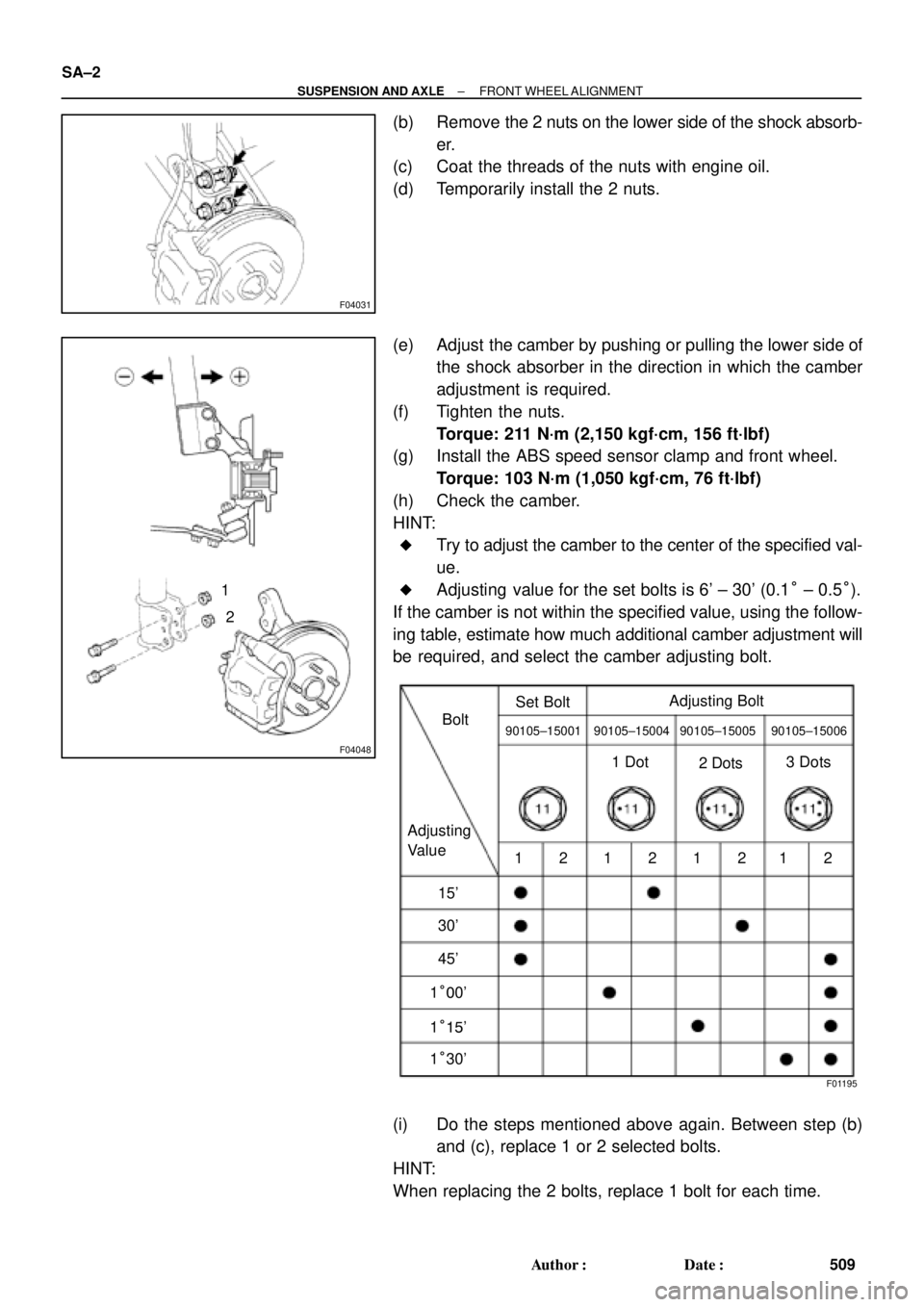
(b) Remove the 2 nuts on the lower side of the shock absorb-
er.
(c) Coat the threads of the nuts with engine oil.
(d) Temporarily install the 2 nuts.
(e) Adjust the camber by pushing or pulling the lower side of
the shock absorber in the direction in which the camber
adjustment is required.
(f) Tighten the nuts.
Torque: 211 N´m (2,150 kgf´cm, 156 ft´lbf)
(g) Install the ABS speed sensor clamp and front wheel.
Torque: 103 N´m (1,050 kgf´cm, 76 ft´lbf)
(h) Check the camber.
HINT:
�Try to adjust the camber to the center of the specified val-
ue.
�Adjusting value for the set bolts is 6' ± 30' (0.1° ± 0.5°).
If the camber is not within the specified value, using the follow-
ing table, estimate how much additional camber adjustment will
be required, and select the camber adjusting bolt.
(i) Do the steps mentioned above again. Between step (b)
and (c), replace 1 or 2 selected bolts.
HINT:
When replacing the 2 bolts, replace 1 bolt for each time.
Page 3647 of 4592

SA1F5±02
± SUSPENSION AND AXLEREAR SHOCK ABSORBER
SA±19
INSTALLATION
1. INSTALL SHOCK ABSORBER WITH COIL SPRING
(a) Install the 3 nuts and shock absorber with the coil spring.
Torque: 39 N´m (400 kgf´cm, 29 ft´lbf)
(b) Install the shock absorber with the coil spring, 2 bolts and nuts.
Torque:
Reused nut: 196 N´m (2,000 kgf´cm, 145 ft´lbf)
New nut: 255 N´m (2,600 kgf´cm, 188 ft´lbf)
HINT:
If reusing the 2 nuts, coat the threads of the 2 nuts with engine oil.
(c) Torque the nut in the center of the suspension support.
Torque: 49 N´m (500 kgf´cm, 36 ft´lbf)
HINT:
If the shock absorber has not been disassembled, it is not necessary to torque the nut.
(d) Install the cap.
2. CONNECT STABILIZER BAR LINK
Torque: 39 N´m (400 kgf´cm, 29 ft´lbf)
HINT:
If the ball joint turns together with the nut, use a hexagon (5 mm) wrench to hold the stud.
3. CONNECT FLEXIBLE HOSE AND ABS SPEED SENSOR WIRE HARNESS CLAMP
Torque:
Flexible hose: 29 N´m (300 kgf´cm, 22 ft´lbf)
ABS speed sensor wire harness: 5.4 N´m (55 kgf´cm, 48 in.´lbf)
4. INSTALL REAR WHEEL
Torque: 103 N´m (1,050 kgf´cm, 76 ft´lbf)
5. INSTALL REAR SEATBACK AND REAR SEAT CUSHION (See page BO±25)
6. CHECK REAR WHEEL ALIGNMENT (See Pub. No. RM654U on page SA±7)
Page 3654 of 4592

Toyota Supports ASE CertificationPage 1 of 1
AC002±00
Title:
A/C COMPRESSOR MAINTENANCE FOR
STORED VEHICLES
Models:
All Models
Technical Service
BULLETIN
July 21, 2000
When a vehicle is stored for a long period (more than one month), the volume of oil
in the A/C compressor may decrease due to oil flow into the condenser, pipes, etc.
If the A/C system is turned on at high engine RPM after a long storage period, A/C
compressor damage may result.
To minimize the possibility of damage to the A/C compressor while storing a vehicle,
perform the following recommended maintenance procedure at
least once a month to
lubricate the compressor.
Recommended
Maintenance Procedure For A/C Compressor Lubrication:
1. Turn
off A/C and blower switches prior to starting engine.
2. Start and warm±up engine until engine speed drops below 1,000 RPM.
3. Turn on the A/C system (including the rear A/C) using the following settings:
�A/C switch: On
�Blower Speed: High
�Engine Speed: Below 1,000 RPM
4. Keep A/C on with engine idling for at least 30 seconds.
5. Turn off A/C system and stop engine.
OP CODEDESCRIPTIONTIMEOPNT1T2
N/ANot Applicable to Warranty ±±±±
HEATING & AIR CONDITIONING
Introduction
Maintenance
Procedure
Warranty
Information
Page 3794 of 4592

Toyota Supports ASE CertificationPage 1 of 1
EG003-03Title:
SULFUR ODOR FROM EXHAUST
Models:
All Models
Technical Service
BULLETIN
February 24, 2003
Some owners of Toyota vehicles may experience a sulfur±like or ªrotten eggº odor from
the exhaust system. Sulfur is a natural component of crude oil from which gasoline is
refined and the amount of sulfur can be decreased through the refining process. The
amount of sulfur in fuel sold in California is regulated, however gasoline sold in other
states can have substantially higher sulfur content. Sulfur content also varies
considerably between gasoline brands and locations.
�All Models.
A sulfur odor emitted from the vehicle's tailpipe does not necessarily indicate that there is
an issue with the engine's running condition, but is most likely directly related to the fuel.
If the vehicle is exhibiting an excessive sulfur odor, the following checks should be
performed:
�If the MIL light is ON, check for DTCs and repair as necessary.
If no trouble is found after performing the above check, recommend the customer try a
different source of fuel.
Replacement of oxygen sensors, air/fuel ratio sensors or catalytic converters will not
reduce the odor and will therefore not
be considered warrantable.
OP CODEDESCRIPTIONTIMEOFPT1T2
N/ANot Applicable to Warranty±±±±
ENGINE
Introduction
Applicable
Vehicles
Repair
Procedure
Warranty
Information
Page 3813 of 4592
Toyota Supports ASE CertificationPage 1 of 1
EG007-02Title:
GENERAL MAINTENANCE TIP
Models:
All '93 ± '03 Models
Technical Service
BULLETIN
March 22, 2002
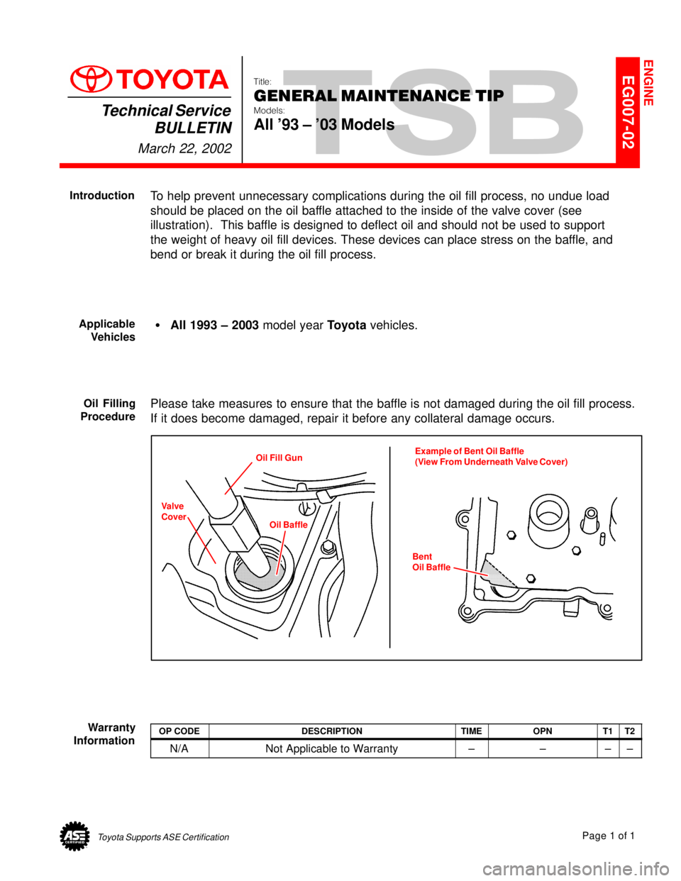
To help prevent unnecessary complications during the oil fill process, no undue load
should be placed on the oil baffle attached to the inside of the valve cover (see
illustration). This baffle is designed to deflect oil and should not be used to support
the weight of heavy oil fill devices. These devices can place stress on the baffle, and
bend or break it during the oil fill process.
�All 1993 ± 2003 model year Toyota vehicles.
Please take measures to ensure that the baffle is not damaged during the oil fill process.
If it does become damaged, repair it before any collateral damage occurs.
Oil Fill Gun
Oil BaffleExample of Bent Oil Baffle
(View From Underneath Valve Cover)
Bent
Oil Baffle
Valve
Cover
OP CODEDESCRIPTIONTIMEOPNT1T2
N/ANot Applicable to Warranty±±±±
ENGINE
Introduction
Applicable
Vehicles
Oil Filling
Procedure
Warranty
Information