Page 1051 of 4592

BR0B1±03
R00591
R00514
R10387
± BRAKEREAR BRAKE PAD
BR±37
2060 Author�: Date�:
REPLACEMENT
1. REMOVE REAR WHEEL
Remove the wheel and temporarily fasten the disc with the hub
nuts.
2. INSPECT PAD LINING THICKNESS
Check the pad thickness through the caliper inspection hole
and replace pads if not within specification.
Minimum thickness: 1.0 mm (0.039 in.)
3. LIFT UP CALIPER
(a) Remove the bolt and flexible hose from the bracket.
(b) Remove the installation bolt from the torque plate.
(c) Lift up the caliper and suspend it securely.
HINT:
Do not disconnect the flexible hose.
4. REMOVE 2 BRAKE PADS
5. REMOVE 4 ANTI±SQUEAL SHIMS
6. REMOVE 4 PAD SUPPORT PLATES
NOTICE:
The support plates can be used again provided that they
have sufficient rebound, no deformation, cracks or wear,
and have had all rust, dirt and foreign particles cleaned off.
7. CHECK DISC THICKNESS AND RUNOUT
(See page BR±42)
8. INSTALL 4 PAD SUPPORT PLATES
9. INSTALL NEW PADS
NOTICE:
When replacing worn pads, the anti±squeal shims must be
replaced together with the pads.
(a) Apply disc brake grease to both side of the inner anti±
squeal shims (See page BR±36).
(b) Install the 2 anti±squeal shims on each pad.
(c) Install 2 pads with the pad wear indicator plate facing up-
ward.
NOTICE:
There should be no oil or grease adhering to the friction
surfaces of the pads or the disc.
10. INSTALL CALIPER
(a) Draw out a small amount of brake fluid from the reservoir.
(b) Press in the piston with a hammer handle or similar imple-
ment.
HINT:
If the piston is difficult to push in, loosen the bleeder plug and
push in the piston while letting some brake fluid escape.
(c) Install the caliper and torque the installation bolt.
Torque: 20 N´m (200 kgf´cm, 14 ft´lbf)
(d) Install the flexible hose and bolt to the bracket.
Torque: 29 N´m (300 kgf´cm, 21 ft´lbf)
Page 1052 of 4592
BR±38
± BRAKEREAR BRAKE PAD
2061 Author�: Date�:
11. INSTALL REAR WHEEL
Torque: 103 N´m (1.050 kgf´cm, 76 ft´lbf)
12. DEPRESS BRAKE PEDAL SEVERAL TIMES
13. CHECK THAT FLUID LEVEL IS AT MAX LINE
Page 1054 of 4592

2. DISCONNECT FLEXIBLE HOSE
(a) Remove the unio")
BR0B3±03
W03263
W03264
BR±40
± BRAKEREAR BRAKE CALIPER
2063 Author�: Date�:
REMOVAL
1. REMOVE REAR WHEEL
Torque: 103 N´m (1.050 kgf´cm, 76 ft´lbf)
2. DISCONNECT FLEXIBLE HOSE
(a) Remove the union bolt and 2 gaskets from the caliper,
then disconnect the flexible hose from the caliper.
Torque: 29 N´m (300 kgf´cm, 21 ft´lbf)
HINT:
At the time of installation, please refer to the following item.
Insert the flexible hose lock securely in the lock hole in the cali-
per.
(b) Use a container to catch the brake fluid as it drains out.
3. REMOVE CALIPER
(a) Remove the installation bolt.
Torque: 20 N´m (200 kgf´cm, 14 ft´lbf)
(b) Remove the caliper from the torque plate.
4. REMOVE 2 BRAKE PADS WITH 4 ANTI±SQUEAL
SHIMS
5. REMOVE 4 PAD SUPPORT PLATES
NOTICE:
At the time of installation, please refer to the following item.
There should be no oil or grease adhering to the friction
surfaces of the pads or disc.
6. REMOVE MAIN PIN
Loosen the main pin installation bolt and remove the main pin.
Torque: 26 N´m (270 kgf´cm, 20 ft´lbf)
Page 1060 of 4592

2. REMOVE REAR DISC BRAKE ASSEMBLY")
BR0B9±03
W03265
R00309
BR3948
R00310
BR±46
± BRAKEPARKING BRAKE
2069 Author�: Date�:
DISASSEMBLY
1. REMOVE REAR WHEEL
Torque: 103 N´m (1.050 kgf´cm, 76 ft´lbf)
2. REMOVE REAR DISC BRAKE ASSEMBLY
(a) Remove the 2 mounting bolts and remove the disc brake
assembly.
Torque: 47 N´m (475 kgf´cm, 34 ft´lbf)
(b) Suspend the disc brake securely. Ensure that the hose is
not stretched.
3. REMOVE DISC
Release the parking brake lever and remove the disc.
HINT:
If the disc cannot be removed easily, turn the shoe adjuster until
the wheel turns freely.
4. REMOVE SHOE RETURN SPRINGS
Using needle±nose pliers, remove the shoe return springs.
5. REMOVE FRONT SHOE ADJUSTER AND TENSION
SPRING
(a) Slide out the front shoe and remove the shoe adjuster.
(b) Remove the shoe strut with the spring.
(c) Remove the shoe hold±down spring cups, spring and pin.
(d) Disconnect the tension spring and remove the front shoe.
6. REMOVE REAR SHOE
(a) Slide out the rear shoe.
(b) Remove the tension spring from the rear shoe.
(c) Remove the shoe hold±down spring cups, spring and pin.
(d) Using needle±nose pliers, disconnect the parking brake
cable from the parking brake shoe lever.
Page 1135 of 4592
CL03J±01
Q10017
Flywheel
Clutch Disc
19 (195, 14)
47 (480, 35)
Clutch Coverx 6
Release Bearing and Hub
Release Fork5S±FE :
Release Fork
39 (400, 29)
5S±FE :
Clutch Disc
N´m (kgf´cm, ft´lbf) : Specified torqueBoot
± CLUTCHCLUTCH UNIT
CL±17
1796 Author�: Date�:
CLUTCH UNIT
COMPONENTS
Page 1139 of 4592
CL03M±02
Q10089
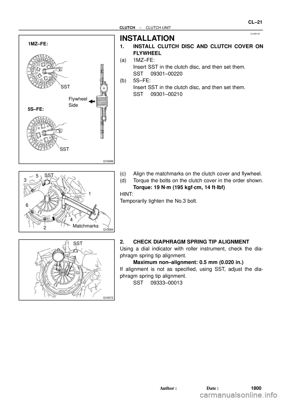
1MZ±FE:
5S±FE:SST
Flywheel
Side
SST
Q10084
SST
1
Matchmarks
4
2
6
35
Q10072
SST
± CLUTCHCLUTCH UNIT
CL±21
1800 Author�: Date�:
INSTALLATION
1. INSTALL CLUTCH DISC AND CLUTCH COVER ON
FLYWHEEL
(a) 1MZ±FE:
Insert SST in the clutch disc, and then set them.
SST 09301±00220
(b) 5S±FE:
Insert SST in the clutch disc, and then set them.
SST 09301±00210
(c) Align the matchmarks on the clutch cover and flywheel.
(d) Torque the bolts on the clutch cover in the order shown.
Torque: 19 N´m (195 kgf´cm, 14 ft´lbf)
HINT:
Temporarily tighten the No.3 bolt.
2. CHECK DIAPHRAGM SPRING TIP ALIGNMENT
Using a dial indicator with roller instrument, check the dia-
phragm spring tip alignment.
Maximum non±alignment: 0.5 mm (0.020 in.)
If alignment is not as specified, using SST, adjust the dia-
phragm spring tip alignment.
SST 09333±00013
Page 1609 of 4592

DI±397
632 Author�: Date�:
6. MECHANICAL SYSTEM TESTS
(a) Measure the stall speed.
The object of this test is to check the overall performance of the transax")
± DIAGNOSTICSAUTOMATIC TRANSAXLE (A140E)
DI±397
632 Author�: Date�:
6. MECHANICAL SYSTEM TESTS
(a) Measure the stall speed.
The object of this test is to check the overall performance of the transaxle and engine by measuring
the stall speeds in the D and R positions.
NOTICE:
�Do the test at normal operating fluid temperature 50 ± 80 °C (122 ± 176 °F).
�Do not continuously run this test for longer than 5 seconds.
�To ensure safety, conduct this test in a wide, clear level area which provides good traction.
�The stall test should always be carried out in pairs. One technician should observe the condi-
tions of wheels or wheel stoppers outside the vehicle while the other is doing the test.
(1) Chock the 4 wheels.
(2) Connect an OBD II scan tool or TOYOTA hand±held tester to DLC3.
(3) Fully apply the parking brake.
(4) Keep your left foot depressing firmly on the brake pedal.
(5) Start the engine.
(6) Shift into the D position. Press all the way down on the accelerator pedal with your right foot.
Quickly read the stall speed at this time.
Stall speed: 2,450 ± 150 rpm
(7) Do the same test in R position.
Stall speed: 2,450 ± 150 rpm
Evaluation:
ProblemPossible cause
(a) Stall speed low in D and R positions
�Engine output may be insufficient
�Stator one±way clutch is operating properly
�HINT: If more than 600 rpm below the specified value, the torque
converter clutch could be faulty.
(b) Stall speed high in D position
�Line pressure too low
�Forward clutch slipping
�No.2 one±way clutch not operating properly
�O/D clutch slipping
(c) Stall speed high in R position
�Line pressure too low
�Direct clutch slipping
�1st & reverse brake slipping
�O/D clutch slipping
(d) Stall speed high in D and R positions
�Line pressure too low
�Improper fluid level
�O/D one±way clutch not operating properly
Page 1657 of 4592

DI±445
680 Author�: Date�:
(f) Inspect and adjust the shift lever position.
When shifting the shift")
Q00199
Q04604
Q04700
Bolt Neutral Basic Line
Groove
Bolt
± DIAGNOSTICSAUTOMATIC TRANSAXLE (A541E)
DI±445
680 Author�: Date�:
(f) Inspect and adjust the shift lever position.
When shifting the shift lever from the N position to other
positions, check that the lever can be shifted smoothly
and accurately to each position and that the position indi-
cator is not aligned with the correct position.
If the indicator is not aligned with the correct position, carry out
the following adjustment procedures.
(1) Loosen the nut on the shift lever.
(2) Push the control shaft fully rearward.
(3) Return the control shaft lever 2 notches to N posi-
tion.
(4) Set the shift lever to N position.
(5) While holding the shift lever lightly toward the R
position side, tighten the shift lever nut.
Torque: 13 N´m (130 kgf´cm, 9 ft´lbf)
(6) Start the engine and make sure that the vehicle
moves forward when shifting the lever from the N to
D position and reverses when shifting it to the R
position.
(g) Inspect and adjust the park/neutral position.
Check that the engine can be started with the shift lever
only in the N or P position, but not in other positions.
If it is not as stated above, carry out the following adjustment
procedures.
(1) Loosen the park/neutral position switch bolt and set
the shift lever to the N position.
(2) Align the groove and neutral basic line.
(3) Hold in position and tighten the bolt.
Torque: 5.4 N´m (55 kgf´cm, 48 in´lbf)
For continuity inspection of the park/neutral position
switch, see page DI±479.
(h) Check the idle speed.
Idle speed: 700 ± 50 rpm
(In N position and air conditioner OFF)
6. MECHANICAL SYSTEM TESTS
(a) Measure the stall speed.
The object of this test is to check the overall performance of the transaxle and engine by measuring
the stall speeds in the D and R positions.
NOTICE:
�Do the test at normal operating fluid temperature 50 ± 80 °C (122 ± 176 °F).
�Do not continuously run this test longer than 5 seconds.
�To ensure safety, conduct this test in a wide, clear level area which provides good traction.
�The stall test should always be carried out in pairs. One technician should observe the condi-
tions of wheels or wheel stoppers outside the vehicle while the other is doing the test.
(1) Chock the 4 wheels.
(2) Connect an OBD II scan tool or TOYOTA hand±held tester to DLC3.
(3) Fully apply the parking brake.
(4) Keep your left foot pressed firmly on the brake pedal.
(5) Start the engine.


47 (480, 35)
Clutch Coverx 6
Release Bearing and Hub
Release Fork5S±FE :
Release Fork
39 (400, 29)
5S±FE :
Clutch Disc
N´m (kgf´cm, ft´lbf) : Sp")