Page 990 of 4592
BO2DN±01
H09249
Luggage Compartment
Trim Front Cover
Rear Bumper Reinforcement
Rear Bumper Energy Absorber
Rear Bumper
Side Retainer
Quarter Air Duct
Rear Bumper Cover Rear Bumper
Side RetainerInner Luggage Compartment
Trim Cover
34 (350, 25)
4.9 (50, 43 in.´lbf)
4.9 (50, 43 in.´lbf)
N´m (kgf´cm, ft´lbf) : Specified TorqueInner Luggage Compartment
Trim Cover
Spare Wheel Cover
4.9 (50, 43 in.´lbf)
4.9 (50, 43 in.´lbf)
4.9 (50, 43 in.´lbf)
BO±4
± BODYREAR BUMPER
543 Author�: Date�:
REAR BUMPER
COMPONENTS
Page 991 of 4592

BO2DO±02
H09250
Luggage Compartment
Door HingeLuggage Compartment DoorLuggage Compartment
Door Hinge
Door Lock Cylinder
Door Lock StrikerDoor Lock
Door Support
Inner Luggage Compartment
Trim Cover
Spare Wheel
Rear SeatbackSpare Wheel Cover
Spare Wheel
Carrier
Spare Wheel
Carrier Spacer
Luggage Compartment
Trim Front Cover
Rear Floor Finish
Side Plate
Rear Seat Outer BeltInner Lower Luggage
Compartment Trim Cover
Rear Seat Outer Belt Rear Floor Finish
Side Plate
Rear Seat CushionRoof Side
Inner Garnish
No. 1 Upper Back Panel Hole CoverPackage Tray Trim High±mounted
Stop Light
Roof Side
Inner Garnish
41 (420, 31)
41 (420, 31)
7.8 (80, 69 in.´lbf)
5.4 (55, 49 in.´lbf)
Luggage Compartment Door Cover
x11
N´m (kgf´cm, ft´lbf) : Specified TorqueReat Combination Light
22 (224, 16)
22 (224, 16)
5.4 (55, 49 in.´lbf)
18 (185, 13)
7.8 (80, 69 in.´lbf)
22 (224, 16)
Rear Floor
Finish Plate
± BODYLUGGAGE COMPARTMENT DOOR AND HINGE
BO±5
544 Author�: Date�:
LUGGAGE COMPARTMENT DOOR AND HINGE
COMPONENTS
Page 992 of 4592

BO2DP±01
H09251
H09252
BO±6
± BODYLUGGAGE COMPARTMENT DOOR AND HINGE
REMOVAL
1. REMOVE LUGGAGE COMPARTMENT DOOR COVER
Remove the 11 clips and luggage compartment door cover.
2. REMOVE LUGGAGE COMPARTMENT DOOR
(a) Disconnect the connectors.
(b) Using a clip remover, disconnect the clamps.
(c) Remove the 4 bolts and door.
Torque: 7.8 N´m (80 kgf´cm, 69 in.´lbf)
3. REMOVE LUGGAGE COMPARTMENT TRIM FRONT
COVER
Using a clip remover, remove the 6 clips and luggage compart-
ment trim front cover.
4. REMOVE SPARE WHEEL COVER
5. REMOVE INNER LUGGAGE COMPARTMENT TRIM
COVER
(a) Using a clip remover, remove the 2 clips and inner lug-
gage compartment trim cover.
(b) Employ the same manner described above to the other
side.
6. REMOVE REAR FLOOR FINISH SIDE PLATES
Using a clip remover, remove the 6 clips and 2 rear floor finish
side plates.
7. REMOVE INNER LOWER LUGGAGE COMPARTMENT
TRIM COVER
(a) Remove the spare wheel carrier, spare wheel carrier
spacer and spare wheel.
(b) Using a clip remover, remove the 3 clips and inner lower
luggage compartment trim cover.
HINT:
Tape the screwdriver tip before use.
Page 1018 of 4592

F05595
F05596
BR0AB±03
F05597
R00252
BR±4
± BRAKEBRAKE FLUID
2027 Author�: Date�:
BRAKE FLUID
BLEEDING
HINT:
If any work is done on the brake system or if air is suspected in
the brake lines, bleed the air from the system.
NOTICE:
Do not let brake fluid remain on a painted surface. Wash it
off immediately.
1. FILL BRAKE RESERVOIR WITH BRAKE FLUID
Check the fluid level in the reservoir after bleeding each wheel.
Add fluid, if necessary.
Fluid: SAEJ1703 or FMVSS No.116 DOT 3
2. BLEED MASTER CYLINDER
HINT:
If the master cylinder has been disassembled or if the reservoir
becomes empty, bleed the air from the master cylinder.
(a) Disconnect the 2 brake lines from the master cylinder.
(b) Slowly depress the brake pedal and hold it.
(c) Block off the outlet plugs with your fingers, and release
the brake pedal.
(d) Repeat (b) and (c) 3 or 4 times.
3. CONNECT VINYL TUBE TO BRAKE CALIPER OR
WHEEL CYLINDER BLEEDER PLUG
Insert the other end of the tube in a half±full container of brake
fluid.
NOTICE:
Bleed air of the rear brake first. If front brake is bled first,
rear brake air cannot be bled.
4. BLEED BRAKE LINE
(a) Slowly depress the brake pedal several times.
(b) While an assistant depresses the pedal, loosen the
bleeder plug until fluid starts to run out. Then tighten the
bleeder plug.
(c) Repeat this procedure until there are no more air bubbles
in the fluid.
Torque: (Bleeder plug)
8.3 N´m (85 kgf´cm, 74 in.´lbf)
5. REPEAT PROCEDURE FOR EACH WHEEL
Page 1037 of 4592
 1MZ±FE engine:
Install a pad wear indicator plate on the inner pad.
(b) Apply disc brake grease to both sides of the inner anti±")
R00595
R02981
± BRAKEFRONT BRAKE PAD
BR±23
2046 Author�: Date�:
(a) 1MZ±FE engine:
Install a pad wear indicator plate on the inner pad.
(b) Apply disc brake grease to both sides of the inner anti±
squeal shims (See page BR±21).
(c) Install the 2 anti±squeal shims on each pad.
(d) Install inner pad with the pad wear indicator plate facing
upward.
(e) Install inner pad.
(f) Install outer pad.
NOTICE:
There should be no oil or grease adhering to the friction
surfaces of the pads or the disc.
(g) 5S±FE engine:
Install the 2 anti±squeal springs.
13. INSTALL CALIPER
(a) Draw out a small amount of brake fluid from the reservoir.
(b) Press in the piston with a hammer handle or similar imple-
ment.
HINT:
If the piston is difficult to push in, loosen the bleeder plug and
push in the piston while letting some brake fluid escape.
(c) Install the caliper.
(d) 5S±FE engine:
Hold the sliding pin and torque the installation bolt.
(e) 1MZ±FE engine:
Install the installation bolt.
Torque: 34 N´m (350 kgf´cm, 25 ft´lbf)
(f) Install the flexible hose and bolt to the bracket.
Torque: 29 N´m (300 kgf´cm, 21 ft´lbf)
14. INSTALL FRONT WHEEL
Torque: 103 N´m (1,050 kgf´cm, 76 ft´lbf)
15. DEPRESS BRAKE PEDAL SEVERAL TIMES
16. CHECK THAT FLUID LEVEL IS AT MAX LINE
Page 1040 of 4592
BR0AR±03
R02840
BR±26
± BRAKEFRONT BRAKE CALIPER
2049 Author�: Date�:
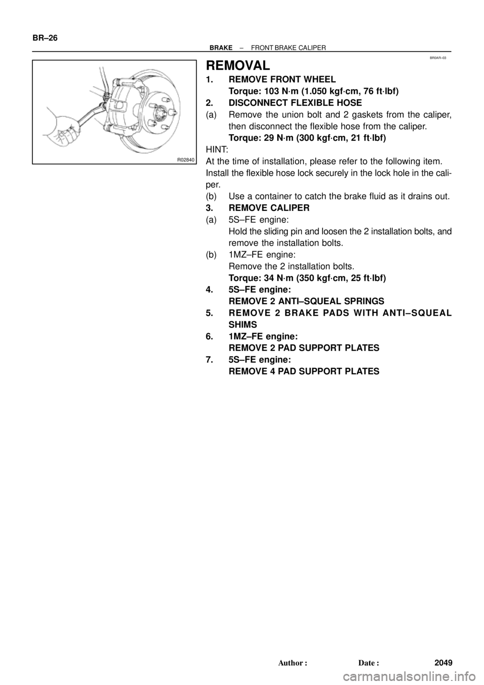
REMOVAL
1. REMOVE FRONT WHEEL
Torque: 103 N´m (1.050 kgf´cm, 76 ft´lbf)
2. DISCONNECT FLEXIBLE HOSE
(a) Remove the union bolt and 2 gaskets from the caliper,
then disconnect the flexible hose from the caliper.
Torque: 29 N´m (300 kgf´cm, 21 ft´lbf)
HINT:
At the time of installation, please refer to the following item.
Install the flexible hose lock securely in the lock hole in the cali-
per.
(b) Use a container to catch the brake fluid as it drains out.
3. REMOVE CALIPER
(a) 5S±FE engine:
Hold the sliding pin and loosen the 2 installation bolts, and
remove the installation bolts.
(b) 1MZ±FE engine:
Remove the 2 installation bolts.
Torque: 34 N´m (350 kgf´cm, 25 ft´lbf)
4. 5S±FE engine:
REMOVE 2 ANTI±SQUEAL SPRINGS
5. REMOVE 2 BRAKE PADS WITH ANTI±SQUEAL
SHIMS
6. 1MZ±FE engine:
REMOVE 2 PAD SUPPORT PLATES
7. 5S±FE engine:
REMOVE 4 PAD SUPPORT PLATES
Page 1045 of 4592
BR0AW±03
W03258
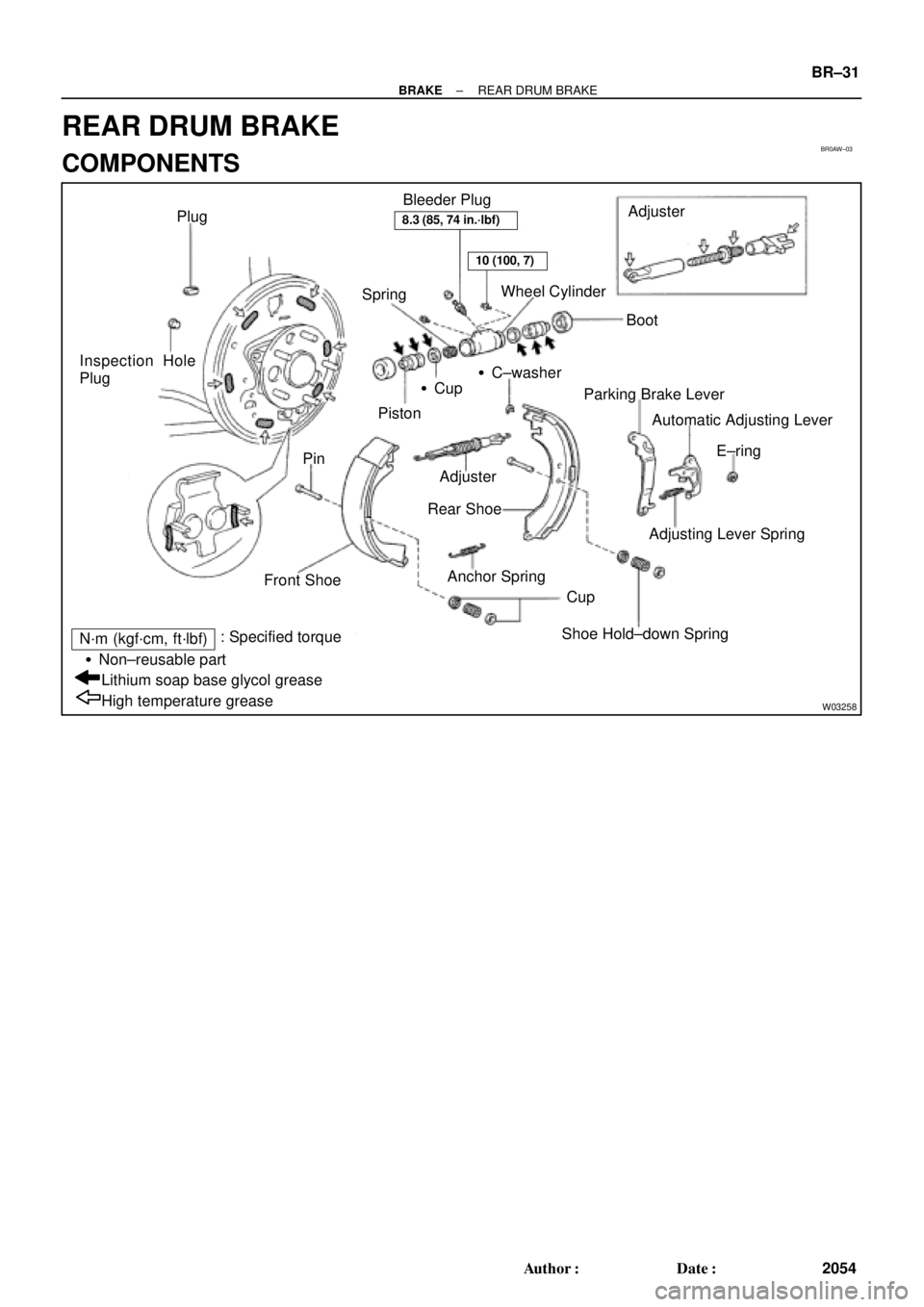
Plug
SpringWheel Cylinder
BootAdjuster
�Cup
Piston�C±washer Inspection Hole
Plug
Pin
Front Shoe
Cup
Shoe Hold±down Spring Adjuster
Rear Shoe
Anchor SpringParking Brake Lever
Automatic Adjusting Lever
E±ring
Adjusting Lever Spring Bleeder Plug
High temperature grease Lithium soap base glycol grease �Non±reusable part
N´m (kgf´cm, ft´lbf): Specified torque
8.3 (85, 74 in.´lbf)
10 (100, 7)
± BRAKEREAR DRUM BRAKE
BR±31
2054 Author�: Date�:
REAR DRUM BRAKE
COMPONENTS
Page 1047 of 4592
 Using SST, remove the shoe hold±down spring, 2 cups
and pin.
SST 09718±00010
(b) Using a scre")
R00248
SST
Z03633
BR1540
SST
± BRAKEREAR DRUM BRAKE
BR±33
2056 Author�: Date�:
5. REMOVE REAR SHOE
(a) Using SST, remove the shoe hold±down spring, 2 cups
and pin.
SST 09718±00010
(b) Using a screwdriver, disconnect the parking brake cable
from the anchor plate.
(c) Using pliers, disconnect the parking brake cable from the
lever and remove the rear shoe together with adjuster.
NOTICE:
Do not allow oil or grease on the rubbing face.
6. REMOVE ADJUSTER FROM REAR SHOE
(a) Remove the adjusting lever spring.
(b) Remove the adjuster together with the return spring.
7. REMOVE AUTOMATIC ADJUSTING LEVER AND
PARKING BRAKE LEVER
(a) Remove the E±ring.
(b) Remove the automatic adjusting lever.
(c) Remove the C±washer.
(d) Remove the parking brake lever.
8. REMOVE WHEEL CYLINDER
(a) Using SST, disconnect the brake line. Use a container to
catch the brake fluid.
Torque: 15 N´m (155 kgf´cm, 11 ft´lbf)
SST 09751±36011
(b) Remove the 2 bolts and the wheel cylinder.
Torque: 10 N´m (100 kgf´cm, 7 ft´lbf)
9. DISASSEMBLE WHEEL CYLINDER
(a) Remove the 2 boots.
(b) Remove the 2 pistons and springs.
(c) Remove the 2 piston cups.