Page 114 of 4592
AUTOMATIC TRANSAXLE UNIT
1913 Author�: Date�:
14. REMOVE EXHAUST MANIFOLD STAY
Remove the 2 bolts and exhaust manifold stay.
Torque: 42 N´m (")
Q10058
Q10059
Q00251
AX±20
± AUTOMATIC TRANSAXLE (A140E)AUTOMATIC TRANSAXLE UNIT
1913 Author�: Date�:
14. REMOVE EXHAUST MANIFOLD STAY
Remove the 2 bolts and exhaust manifold stay.
Torque: 42 N´m (430 kgf´cm, 31 ft´lbf)
15. REMOVE TRANSAXLE±TO±ENGINE BOLT
Torque: 66 N´m (670 kgf´cm, 48 ft´lbf)
16. REMOVE ENGINE HOOD
(a) Disconnect the washer pipe.
(b) Remove the 4 bolts and engine hood.
Torque: 14 N´m (145 kgf´cm, 10 ft´lbf)
17. RAISE AND SUPPORT VEHICLE SECURELY
18. REMOVE FRONT WHEELS
Torque: 103 N´m (1,050 kgf´cm, 76 ft´lbf)
19. REMOVE ENGINE UNDER COVER AND CENTER EN-
GINE UNDER COVER
20. DISCONNECT SHIFT CONTROL CABLE
(a) Remove the nut and disconnect the shift control cable
from the park/neutral position switch.
Torque: 15 N´m (150 kgf´cm, 11 ft´lbf)
(b) Remove the clip and disconnect the shift control cable
from the bracket.
21. REMOVE DIFFERENTIAL FLUID DRAIN PLUG AND
GASKET
HINT:
At the time of installation, please refer to the following item.
Replace the used gasket with a new gasket.
22. DRAIN DIFFERENTIAL FLUID
23. REMOVE LH AND RH FENDER APRON SEALS
24. REMOVE LH AND RH DRIVE SHAFTS
(See page SA±17)
Page 119 of 4592
AX03I±01
AT3412
± AUTOMATIC TRANSAXLE (A140E)AUTOMATIC TRANSAXLE UNIT
AX±25
1918 Author�: Date�:
INSTALLATION
1. CHECK TORQUE CONVERTER CLUTCH INSTALLA-
TION
Using a scale and a straight edge, measure to the distance from
the installed surface to the transaxle housing.
Correct distance: 13.0 mm (0.512 in.) or more
2. TRANSAXLE INSTALLATION
Installation is in the reverse order of removal (See page
AX±19).
HINT:
After installation, check and inspect items as follows.
�Fluid level (See page DI±389)
�Front wheel alignment (See page SA±4)
�Road test of the vehicle
�Engine hood (See page BO±10)
Page 145 of 4592
AUTOMATIC TRANSAXLE UNIT
1944 Author�: Date�:
12. REMOVE 2 FRONT SIDE ENGINE MOUNTING BOLTS
Torque:
TMC Made: 80 N´m (820 kgf´cm, 59")
Q06478
Q10286
Q06530
Q10038
AX±24
± AUTOMATIC TRANSAXLE (A541E)AUTOMATIC TRANSAXLE UNIT
1944 Author�: Date�:
12. REMOVE 2 FRONT SIDE ENGINE MOUNTING BOLTS
Torque:
TMC Made: 80 N´m (820 kgf´cm, 59 ft´lbf)
TMMK Made:
Green color bolt: 66 N´m (670 kgf´cm, 48 ft´lbf)
Silver color bolt: 44 N´m (440 kgf´cm, 32 ft´lbf)
13. REMOVE STARTER AND A/T SHIFT CABLE CLAMP
(a) Disconnect the connector and remove the nut.
(b) Remove the 2 bolts, starter and A/T shift cable clamp.
Torque: 39 N´m (400 kgf´cm, 29 ft´lbf)
14. REMOVE EXHAUST MANIFOLD BRACKET MOUNT-
ING BOLT
Torque:
Except California: 20 N´m (200 kgf´cm, 15 ft´lbf)
California: 34 N´m (350 kgf´cm, 25 ft´lbf)
15. REMOVE 5 TRANSAXLE±TO±ENGINE BOLTS AND
DISCONNECT GROUND TERMINAL
Torque: 66 N´m (670 kgf´cm, 48 ft´lbf)
16. REMOVE ENGINE HOOD
(a) Disconnect the washer pipe.
(b) Remove the 4 bolts and engine hood.
Torque: 26 N´m (265 kgf´cm, 19 ft´lbf)
17. RAISE AND SUPPORT VEHICLE SECURELY
18. REMOVE FRONT WHEELS
Torque: 103 N´m (1,050 kgf´cm, 76 ft´lbf)
19. REMOVE DIFFERENTIAL FLUID DRAIN PLUG AND
GASKET
HINT:
At the time of installation, please refer to the following item.
Replace the used gasket with a new gasket.
20. DRAIN DIFFERENTIAL FLUID
21. REMOVE LH AND RH ENGINE SIDE COVERS
22. REMOVE LH AND RH FRONT DRIVE SHAFTS
(See page SA±25)
Page 150 of 4592
AX03Z±01
AT3412
± AUTOMATIC TRANSAXLE (A541E)AUTOMATIC TRANSAXLE UNIT
AX±29
1949 Author�: Date�:
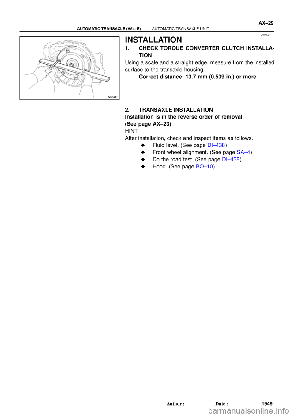
INSTALLATION
1. CHECK TORQUE CONVERTER CLUTCH INSTALLA-
TION
Using a scale and a straight edge, measure from the installed
surface to the transaxle housing.
Correct distance: 13.7 mm (0.539 in.) or more
2. TRANSAXLE INSTALLATION
Installation is in the reverse order of removal.
(See page AX±23)
HINT:
After installation, check and inspect items as follows.
�Fluid level. (See page DI±438)
�Front wheel alignment. (See page SA±4)
�Do the road test. (See page DI±438)
�Hood. (See page BO±10)
Page 157 of 4592
 Precoated parts are indicated in the component il-
lustrations by the º�º symbol.
7")
INTRODUCTIONGENERAL REPAIR INSTRUCTIONS ±
IN±5
the specified seal lock adhesive to the bolt, nut or
threads.
(c) Precoated parts are indicated in the component il-
lustrations by the º�º symbol.
7. When necessary, use a sealer on gaskets to prevent
leaks.
8. Carefully observe all specifications for bolt tightening
torques. Always use a torque wrench.
9. Use of special service tools (SST) and special service ma-
terials (SSM) may be required, depending on the nature
of the repair. Be sure to use SST and SSM where speci-
fied and follow the proper work procedure. A list of SST
and SSM can be found at the preparation of AX section.
10. When replacing fuses, be sure the new fuse has the cor-
rect amperage rating. DO NOT exceed the rating or use
one with a lower rating.
11. To pull apart electrical connectors, pull on the connector
itself, not the wires.
12. Care must be taken when jacking up and supporting the
vehicle. Be sure to lift and support the vehicle at the prop-
er locations.
(a) If the vehicle is to be jacked up only at the front or
rear end, be sure to block the wheels at the opposite
end in order to ensure safety.
(b) After the vehicle is jacked up, be sure to support it on
stands. It is extremely dangerous to do any work on
a vehicle raised on a jack alone, even for a small job
that can be finished quickly.
Page 300 of 4592
 Precoated parts are indicated in the component il-
lustrations by the º�º symbol.
7")
INTRODUCTIONGENERAL REPAIR INSTRUCTIONS ±
IN±5
the specified seal lock adhesive to the bolt, nut or
threads.
(c) Precoated parts are indicated in the component il-
lustrations by the º�º symbol.
7. When necessary, use a sealer on gaskets to prevent
leaks.
8. Carefully observe all specifications for bolt tightening
torques. Always use a torque wrench.
9. Use of special service tools (SST) and special service ma-
terials (SSM) may be required, depending on the nature
of the repair. Be sure to use SST and SSM where speci-
fied and follow the proper work procedure. A list of SST
and SSM can be found at the preparation of AX section.
10. When replacing fuses, be sure the new fuse has the cor-
rect amperage rating. DO NOT exceed the rating or use
one with a lower rating.
11. To pull apart electrical connectors, pull on the connector
itself, not the wires.
12. Care must be taken when jacking up and supporting the
vehicle. Be sure to lift and support the vehicle at the prop-
er locations.
(a) If the vehicle is to be jacked up only at the front or
rear end, be sure to block the wheels at the opposite
end in order to ensure safety.
(b) After the vehicle is jacked up, be sure to support it on
stands. It is extremely dangerous to do any work on
a vehicle raised on a jack alone, even for a small job
that can be finished quickly.
Page 443 of 4592
 Precoated parts are indicated in the component il-
lustrations by the º�º symbol.
7")
INTRODUCTIONGENERAL REPAIR INSTRUCTIONS ±
IN±5
the specified seal lock adhesive to the bolt, nut or
threads.
(c) Precoated parts are indicated in the component il-
lustrations by the º�º symbol.
7. When necessary, use a sealer on gaskets to prevent
leaks.
8. Carefully observe all specifications for bolt tightening
torques. Always use a torque wrench.
9. Use of special service tools (SST) and special service ma-
terials (SSM) may be required, depending on the nature
of the repair. Be sure to use SST and SSM where speci-
fied and follow the proper work procedure. A list of SST
and SSM can be found at the preparation of AX section.
10. When replacing fuses, be sure the new fuse has the cor-
rect amperage rating. DO NOT exceed the rating or use
one with a lower rating.
11. To pull apart electrical connectors, pull on the connector
itself, not the wires.
12. Care must be taken when jacking up and supporting the
vehicle. Be sure to lift and support the vehicle at the prop-
er locations.
(a) If the vehicle is to be jacked up only at the front or
rear end, be sure to block the wheels at the opposite
end in order to ensure safety.
(b) After the vehicle is jacked up, be sure to support it on
stands. It is extremely dangerous to do any work on
a vehicle raised on a jack alone, even for a small job
that can be finished quickly.
Page 916 of 4592

BO0MB±01
N20950
Instrument Panel ReinforcementNN
DD
No.2 Instrumental Panel Bracket
No.1 Instrumental Panel Bracket
No.2 Instrumental Panel Brace
QQH N
N
N
N
GG
NG
NOB
NN
Instrument Panel Brace Mount
No.1 Instrument
Panel BraceFront Pillar Garnish
Front Pillar
GarnishFront
Passenger
Airbag
Assembly
20 (200, 14)
No.2 Side Defroster Nozzle
Cowl Side Trim
Front Door Openin
g
Cover
Instrument Panel
C
Remote Control
Mirror Hole Base
Upper Column
CoverHazard Warning
Switch
Lower Finish
PlateGlove Compartment
Door Finish PlateFront Door
Inside Scuff Plate
FFF
FJ
Glove
Compartment
No.2 Lower
Panel A
A
Cluster Finish
Panel
Lower Column
Cover
Front Door
Opening
Cover
Cowl Side
TrimD
DD
D
D
F
AA
Lower Panel
InsertCoin
BoxCombination SwitchCombination
MeterRadio Assembly
Center Cluster
Finish Panel
A/C
Control Assembly
35 (360, 26)
Steering
Wheel
Pad Steering Wheel No.1 Lower
Panel
Front Door
Inside Scuff PlateFront Console
Box
Center Console
Upper PanelF
F
B
B
Rear Console
Box
N´m (kgf´cm, ft´lbf) : Specified torque BO±72
± BODYINSTRUMENT PANEL
2420 Author�: Date�:
INSTRUMENT PANEL
COMPONENTS