Page 2293 of 4592
 Measure the stall speed.
The object of this test is to check the overall performance of the transaxle and engine by measuring
t")
± DIAGNOSTICSAUTOMATIC TRANSAXLE
DI±141
6. MECHANICAL SYSTEM TESTS
(a) Measure the stall speed.
The object of this test is to check the overall performance of the transaxle and engine by measuring
the stall speeds in the D and R positions.
NOTICE:
�Do the test at normal operating fluid temperature 50 ± 80 °C (122 ± 176 °F).
�Do not continuously run this test for longer than 5 seconds.
�To ensure safety, conduct this test in a wide, clear level area which provides good traction.
�The stall test should always be carried out in pairs. One technician should observe the condi-
tions of wheels or wheel stoppers outside the vehicle while the other is doing the test.
(1) Chock the 4 wheels.
(2) Connect an OBD II scan tool or hand±held tester to DLC3.
(3) Fully apply the parking brake.
(4) Keep your left foot depressing firmly on the brake pedal.
(5) Start the engine.
(6) Shift into the D position. Press all the way down on the accelerator pedal with your right foot.
Quickly read the stall speed at this time.
Stall speed: 2,450 ± 150 rpm
(7) Do the same test in R position.
Stall speed: 2,450 ± 150 rpm
Evaluation:
ProblemPossible cause
(a) Stall speed low in D and R positions
�Engine output may be insufficient
�Stator one±way clutch is operating properly
�HINT: If more than 600 rpm below the specified value, the torque
converter clutch could be faulty.
(b) Stall speed high in D position
�Line pressure too low
�Forward clutch slipping
�No.2 one±way clutch not operating properly
�O/D clutch slipping
(c) Stall speed high in R position
�Line pressure too low
�Direct clutch slipping
�1st & reverse brake slipping
�O/D clutch slipping
(d) Stall speed high in D and R positions
�Line pressure too low
�Improper fluid level
�O/D one±way clutch not operating properly
Page 2579 of 4592
TIMING BELT
1200 Author�: Date�:
(3) Remove the backing paper from a new gasket and
install the gasket evenly to the part of the timing")
S05596
S05296
S05249
S05609
EM±28
± ENGINE MECHANICAL (5S±FE)TIMING BELT
1200 Author�: Date�:
(3) Remove the backing paper from a new gasket and
install the gasket evenly to the part of the timing belt
cover shaded black in the illustration.
(4) After installing the gasket, press down on it so that
the adhesive firmly sticks to the timing belt cover.
(b) Install the belt cover with the 4 bolts.
(c) Install the engine wire clamp.
14. INSTALL SPARK PLUGS
(a) Install the 4 spark plugs.
(b) Connect the 4 high±tension cords to the spark plugs.
(c) Install the 4 high±tension cords to the clamps on the cylin-
der head cover.
15. INSTALL NO.2 RH ENGINE MOUNTING BRACKET
(a) Install the mounting bracket with the 3 bolts.
(b) Alternately tighten the 3 bolts in several passes.
Torque: 52 N´m (530 kgf´cm, 38 ft´lbf)
16. INSTALL ENGINE MOVING CONTROL ROD
(a) Temporarily install the control rod with the 3 bolt.
(b) Alternately tighten the 3 bolts in several passes.
Torque: 64 N´m (650 kgf´cm, 47 ft´lbf)
17. CONNECT GROUND STRAP CONNECTOR
18. INSTALL PS PUMP DRIVE BELT
Install the drive belt with the 2 bolts.
19. INSTALL RH FRONT FENDER APRON SEAL
20. INSTALL RH FRONT WHEEL
21. INSTALL GENERATOR (See page CH±16)
Page 2618 of 4592
S05316
M/T
Engine
No.2 Exhaust
Manifold Stay
(TMMK Made)
(TMC Made)
Exhaust Pipe Bracket
Oil Pan
Insulator
No.1 Exhaust
Manifold Stay
Back±Up Light Switch ConnectorNo.2 Rear End Plate Flywheel
LH Stiffener Plate
Clutch Disk
Clutch Cover
Engine Wire
VSS Connector
Wire Clamp
Ground Strap
Transaxle No.1 Rear End PlateIntake Manifold
Stay RH Stiffener Plate
N´m (kgf´cm, ft´lbf)
� Precoated partx 8
88 (900, 65)
19 (195, 14)
64(650, 47)
64(650, 47)
64(650, 47)64(650, 47)
�
: Specified torquex 6
± ENGINE MECHANICAL (5S±FE)ENGINE UNIT
EM±67
1239 Author�: Date�:
Page 2625 of 4592
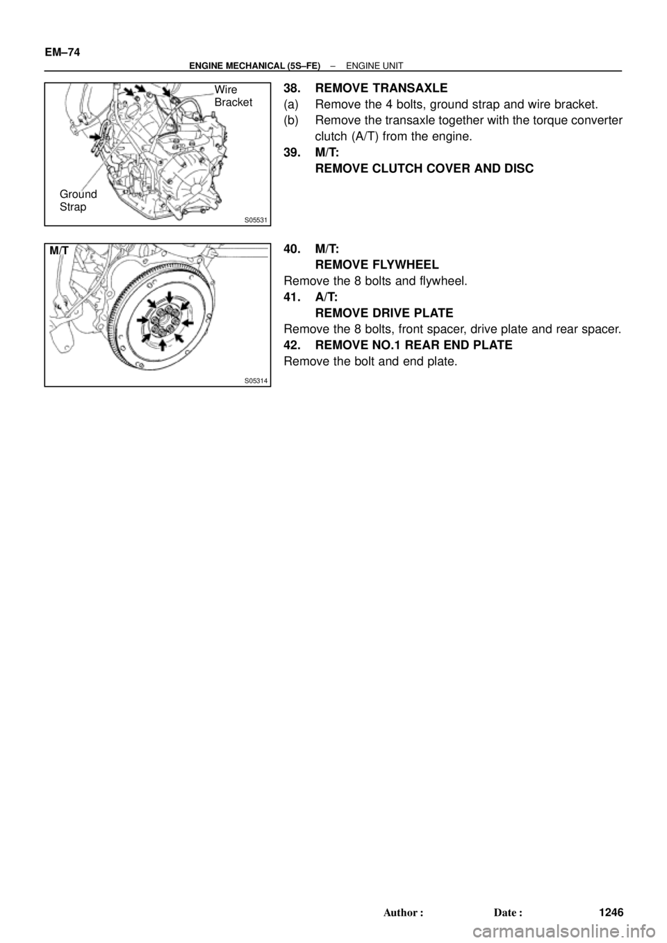
S05531
Wire
Bracket
Ground
Strap
S05314
M/T EM±74
± ENGINE MECHANICAL (5S±FE)ENGINE UNIT
1246 Author�: Date�:
38. REMOVE TRANSAXLE
(a) Remove the 4 bolts, ground strap and wire bracket.
(b) Remove the transaxle together with the torque converter
clutch (A/T) from the engine.
39. M/T:
REMOVE CLUTCH COVER AND DISC
40. M/T:
REMOVE FLYWHEEL
Remove the 8 bolts and flywheel.
41. A/T:
REMOVE DRIVE PLATE
Remove the 8 bolts, front spacer, drive plate and rear spacer.
42. REMOVE NO.1 REAR END PLATE
Remove the bolt and end plate.
Page 2626 of 4592
ENGINE UNIT
EM±75
1247 Author�: Date�:
INSTALLATION
1. INSTALL NO.1 REAR END PLATE
Install the")
EM08G±04
EM7333
Z18989
M/T
1
3
5
8
2 4 67
S05531
Wire
Bracket
Ground
Strap
± ENGINE MECHANICAL (5S±FE)ENGINE UNIT
EM±75
1247 Author�: Date�:
INSTALLATION
1. INSTALL NO.1 REAR END PLATE
Install the end plate with the bolt.
Torque: 9.3 N´m (95 kgf´cm, 82 in.´lbf)
2. M/T:
INSTALL FLYWHEEL
(a) Apply adhesive to 2 or 3 threads of the bolt end.
Adhesive:
Part No. 08833±00070, THREE BOND 1324 or equiva-
lent
(b) Install the flywheel on the crankshaft.
(c) Install and uniformly tighten the 8 bolts in several passes,
in the sequence shown.
Torque: 88 N´m (900 kgf´cm, 65 ft´lbf)
3. A/T:
INSTALL DRIVE PLATE (See step 2)
Torque: 83 N´m (850 kgf´cm, 61 ft´lbf)
4. M/T:
INSTALL CLUTCH DISC AND COVER
5. A/T:
CHECK TORQUE CONVERTER CLUTCH INSTALLA-
TION (A140E: See page AX±25)
6. INSTALL TRANSAXLE TO ENGINE
(a) Attach the transaxle to the engine.
(b) Install the ground strap, wire bracket and 4 bolts.
Torque:
46 N´m (470 kgf´cm, 34 ft´lbf) for 14 mm head
64 N´m (650 kgf´cm, 47 ft´lbf) for 17 mm head
Page 2775 of 4592
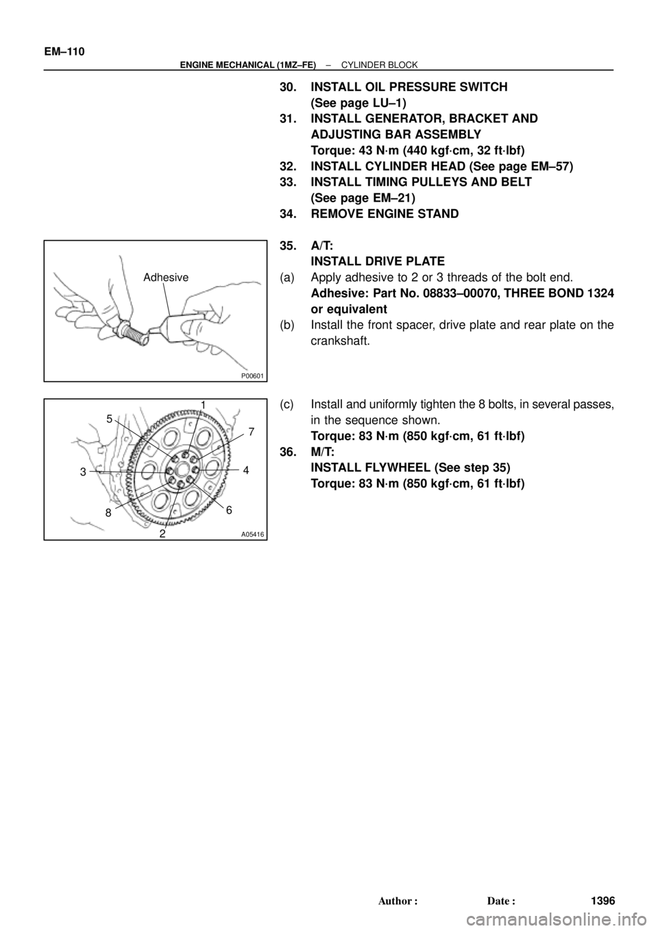
P00601
Adhesive
A05416
1
2 34 5
67
8
EM±110
± ENGINE MECHANICAL (1MZ±FE)CYLINDER BLOCK
1396 Author�: Date�:
30. INSTALL OIL PRESSURE SWITCH
(See page LU±1)
31. INSTALL GENERATOR, BRACKET AND
ADJUSTING BAR ASSEMBLY
Torque: 43 N´m (440 kgf´cm, 32 ft´lbf)
32. INSTALL CYLINDER HEAD (See page EM±57)
33. INSTALL TIMING PULLEYS AND BELT
(See page EM±21)
34. REMOVE ENGINE STAND
35. A/T:
INSTALL DRIVE PLATE
(a) Apply adhesive to 2 or 3 threads of the bolt end.
Adhesive: Part No. 08833±00070, THREE BOND 1324
or equivalent
(b) Install the front spacer, drive plate and rear plate on the
crankshaft.
(c) Install and uniformly tighten the 8 bolts, in several passes,
in the sequence shown.
Torque: 83 N´m (850 kgf´cm, 61 ft´lbf)
36. M/T:
INSTALL FLYWHEEL (See step 35)
Torque: 83 N´m (850 kgf´cm, 61 ft´lbf)
Page 2912 of 4592
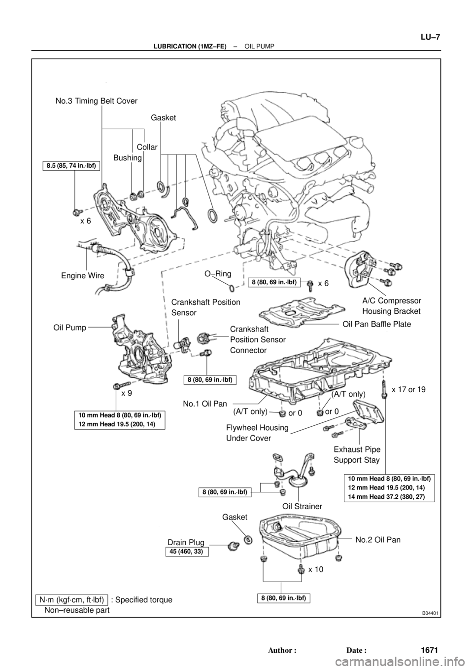
B04401
N´m (kgf´cm, ft´lbf) : Specified torque
� Non±reusable partNo.3 Timing Belt Cover
Gasket
BushingCollar
A/C Compressor
Housing Bracket
Oil Pan Baffle Plate
Crankshaft
Position Sensor
Connector Crankshaft Position
Sensor
Oil PumpEngine Wire
Flywheel Housing
Under Cover
Exhaust Pipe
Support Stay
Oil Strainer
No.2 Oil Pan
x 10x 6
x 9� O±Ring
No.1 Oil Pan
� Gasket
Drain Plug
8.5 (85, 74 in.´lbf)
8 (80, 69 in.´lbf)
8 (80, 69 in.´lbf)
10 mm Head 8 (80, 69 in.´lbf)
12 mm Head 19.5 (200, 14)
10 mm Head 8 (80, 69 in.´lbf)
12 mm Head 19.5 (200, 14)
14 mm Head 37.2 (380, 27)
8 (80, 69 in.´lbf)
45 (460, 33)
8 (80, 69 in.´lbf)
x 6
x 17 or 19
(A/T only)(A/T only)or 0or 0
± LUBRICATION (1MZ±FE)OIL PUMP
LU±7
1671 Author�: Date�:
Page 2922 of 4592
OIL PUMP
LU±17
1681 Author�: Date�:
(b) Appl")
B04402
A Region ºXºRegion ºYº
A
CB B
C
Seal Width
Type A: 4 ± 5 mm
Type B: 3 ± 4 mmRegion ºXºRegion ºYº
AC Type A
Type B
± LUBRICATION (1MZ±FE)OIL PUMP
LU±17
1681 Author�: Date�:
(b) Apply seal packing to the oil pan as shown in the illustra-
tion.
Seal packing: Part No. 08826±00080 or equivalent
Region ºXº is at the outer side of the bolt hole.
Region ºYº is at the inner side of the bolt hole.
�Install a nozzle that has been cut to a 4 ± 5 mm (0.16
± 0.20 in.) (Type A) or 3 ± 4 mm (0.12 ± 0.16 in.)
(Type B) opening.
HINT:
Avoid applying an excessive amount to the surface.
�Parts must be assembled within 3 minutes of ap-
plication. Otherwise the material must be removed
and reapplied.
�Immediately remove nozzle from the tube and rein-
stall cap.
(c) Install the oil pan with the 19 bolts (or 17 bolts and 2 nuts).
Uniformly tighten the bolts and nuts in several passes.
Torque:
10 mm head: 8 N´m (80 kgf´cm, 69 in.´lbf)
12 mm head: 19.5 N´m (200 kgf´cm, 14 ft´lbf)
14 mm head: 37.2 N´m (380 kgf´cm, 27 ft´lbf)
(d) Install the flywheel housing under cover and exhaust pipe
support stay with the 2 bolts.
Torque: 7.8 N´m (80 kgf´cm, 69 in.´lbf)
5. INSTALL OIL STRAINER
Install a new gasket and the oil strainer with the bolt and 2 nuts.
Torque: 8 N´m (80 kgf´cm, 69 in.´lbf)
6. INSTALL NO.2 OIL PAN
(a) Remove any old packing (FIPG) material and be careful
not to drop any oil on the contact surface of the No.1 and
No.2 oil pans.
�Using a razor blade and gasket scraper, remove all
the old packing (FIPG) material from the gasket sur-
faces and sealing grooves.
�Thoroughly clean all components to remove all the
loose material.
�Using a non±residue solvent, clean both sealing
surfaces.
NOTICE:
Do not use a solvent which will affect the painted surfaces.

(TMC Made)
Exhaust Pipe Bracket
Oil Pan
Insulator
No.1 Exhaust
Manifold Stay
Back±Up Light Switch ConnectorNo.2 Rear End Plate Flywheel
LH Sti")