Page 3515 of 4592
SR06H±03
W03348
Torx ScrewSteering Wheel Pad
Steering Wheel
Torx Screw
Steering Wheel Lower
No.2 Cover
Steering Column Assembly
Intermediate Shaft Assembly
No.1 Lower Instrument Panel Combination Switch
(w/ Spiral Cable)Steering Wheel Lower
No.2 Cover
Column
Upper Cover
Lower No.2
Cover
Column Lower Cover
Lower Instrument
Finish Panel
Hood Lock Control Cable
Clip
Front Door Inside Scuff Plate
Cowl Side Trim LH Lower
Instrument Panel
35 (360, 26)
25 (260, 19)
7.1 (72, 63 in.´lbf)
35 (360, 26)
35 (360, 26)
7.1 (72, 63 in.´lbf)
N´m (kgf´cm, ft´lbf) : Specified torque
± STEERINGTILT STEERING COLUMN
SR±9
2104 Author�: Date�:
TILT STEERING COLUMN
COMPONENTS
Page 3522 of 4592
 Torque the 4 column assembly set nuts.
Torque:")
SR06M±01
W03303
Matchmarks
W02655
Mark SR±16
± STEERINGTILT STEERING COLUMN
2111 Author�: Date�:
INSTALLATION
1. INSTALL STEERING COLUMN ASSEMBLY
(a) Torque the 4 column assembly set nuts.
Torque: 25 N´m (260 kgf´cm, 19 ft´lbf)
(b) Connect the connectors.
2. INSTALL INTERMEDIATE SHAFT ASSEMBLY
Torque the bolt.
Torque: 35 N´m (360 kgf´cm, 26 ft´lbf)
3. CONNECT INTERMEDIATE SHAFT ASSEMBLY
(a) Align the matchmarks on the intermediate shaft and con-
trol valve shaft.
(b) Torque the bolt.
Torque: 35 N´m (360 kgf´cm, 26 ft´lbf)
4. INSTALL SPIRAL CABLE
(See page BE±23)
5. INSTALL COMBINATION SWITCH WITH SPIRAL
CABLE
(a) Tighten the 3 screws.
(b) Connect the airbag connector.
(c) Connect the 3 connectors.
6. INSTALL LOWER INSTRUMENT FINISH PANEL
7. INSTALL LH LOWER INSTRUMENT PANEL
Tighten the 4 bolts.
8. INSTALL No.1 LOWER INSTRUMENT PANEL
(a) Connect the hood lock control cable.
(b) Tighten the 2 screws.
9. INSTALL COWL SIDE TRIM
Install the clip.
10. INSTALL FRONT DOOR INSIDE SCUFF PLATE
11. INSTALL UPPER AND LOWER COLUMN COVERS
(a) Tighten the 3 screws.
(b) Install the lower No.2 cover to the lower cover.
12. CENTER SPIRAL CABLE
(a) Check that the front wheels are facing straight ahead.
(b) Turn the cable counterclockwise by hand until it becomes
harder to turn the cable.
(c) Then rotate the cable clockwise about 3 turns to align the
mark.
HINT:
The cable will rotate about 3 turns to either left or right of the
center.
Page 3523 of 4592
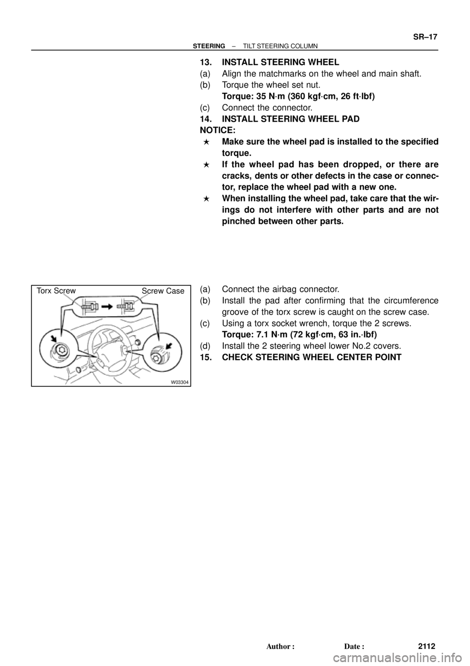
W03304
Torx Screw
Screw Case
± STEERINGTILT STEERING COLUMN
SR±17
2112 Author�: Date�:
13. INSTALL STEERING WHEEL
(a) Align the matchmarks on the wheel and main shaft.
(b) Torque the wheel set nut.
Torque: 35 N´m (360 kgf´cm, 26 ft´lbf)
(c) Connect the connector.
14. INSTALL STEERING WHEEL PAD
NOTICE:
�Make sure the wheel pad is installed to the specified
torque.
�If the wheel pad has been dropped, or there are
cracks, dents or other defects in the case or connec-
tor, replace the wheel pad with a new one.
�When installing the wheel pad, take care that the wir-
ings do not interfere with other parts and are not
pinched between other parts.
(a) Connect the airbag connector.
(b) Install the pad after confirming that the circumference
groove of the torx screw is caught on the screw case.
(c) Using a torx socket wrench, torque the 2 screws.
Torque: 7.1 N´m (72 kgf´cm, 63 in.´lbf)
(d) Install the 2 steering wheel lower No.2 covers.
15. CHECK STEERING WHEEL CENTER POINT
Page 3554 of 4592

or less
SST
W04231
Fulcrum
LengthSST SR±48
± STEERINGPOWER STEERING GEAR
2143 Author�: Date�:
18. INSTALL RH AND LH RACK BOOTS, CLAMPS AND
CLIPS
(a) Ensure that the ste")
R11669
W04223
2 mm
(0.79 in.)
or less
SST
W04231
Fulcrum
LengthSST SR±48
± STEERINGPOWER STEERING GEAR
2143 Author�: Date�:
18. INSTALL RH AND LH RACK BOOTS, CLAMPS AND
CLIPS
(a) Ensure that the steering rack hole is not clogged with
grease.
HINT:
If the hole is clogged, the pressure inside the boot will change
after it is assembled and the steering wheel is turned.
(b) Install the boot.
NOTICE:
Be careful not to damage or twist the boot.
(c) Using SST, tighten the clamp as shown in the illustration.
SST 09521±24010
19. INSTALL RH AND LH TIE ROD ENDS AND LOCK NUTS
(a) Screw the lock nut and tie rod end onto the rack end until
the matchmarks are aligned.
(b) After adjusting toe±in, torque the nut.
(See page SA±4)
Torque: 74 N´m (750 kgf´cm, 54 ft´lbf)
20. INSTALL 2 TURN PRESSURE TUBES
(a) Coat 2 new O±rings with power steering fluid and install
them to the tube.
(b) Using SST, install the tube.
SST 09633±00020
Torque: 10 N´m (102 kgf´cm, 7 ft´lbf)
HINT:
�Use a torque wrench with a fulcrum length of 250 mm
(9.84 in.).
�This torque value is effective in case that SST is parallel
to a torque wrench.
Page 3555 of 4592
 Install the gear assembly from the LH of the vehicle.
NOTICE")
SR06Y±01
W04224
SST
Fulcrum
Length
± STEERINGPOWER STEERING GEAR
SR±49
2144 Author�: Date�:
INSTALLATION
1. INSTALL PS GEAR ASSEMBLY
(a) Install the gear assembly from the LH of the vehicle.
NOTICE:
Do not damage the turn pressure tubes.
(b) Torque the 2 gear assembly set bolts and nuts.
Torque: 181 N´m (1,850 kgf´cm, 134 ft´lbf)
HINT:
Lift up the stabilizer bar and install the bolts.
2. INSTALL NO.1 FUEL TUBE PROTECTOR
Install the 2 bolts and nut.
3. CONNECT STABILIZER BAR
Torque the 4 bolts.
Torque: 19 N´m (195 kgf´cm, 14 ft´lbf)
4. CONNECT PRESSURE FEED AND RETURN TUBES
Using SST, connect the tube.
SST 09631±22020
Torque: 32 N´m (326 kgf´cm, 24 ft´lbf)
HINT:
�Use a torque wrench with a fulcrum length of 300 mm
(11.81 in.).
�This torque value is effective in case that SST is parallel
to a torque wrench.
5. CONNECT CLAMP PLATE
Torque the nut.
Torque: 10 N´m (100 kgf´cm, 7 ft´lbf)
6. CONNECT INTERMEDIATE SHAFT ASSEMBLY
(See page SR±16)
7. CONNECT RH AND LH TIE ROD ENDS
(See page SA±10)
8. POSITION FRONT WHEELS FACING STRAIGHT
AHEAD
HINT:
Do it with the front of the vehicle jacked up.
9. CENTER SPIRAL CABLE
(See page SR±16)
10. INSTALL STEERING WHEEL
(a) Install the wheel at straight±ahead position.
(b) Temporarily tighten the wheel set nut.
(c) Connect the connector.
11. BLEED POWER STEERING SYSTEM
(See page SR±4)
12. CHECK STEERING WHEEL CENTER POINT
Page 3556 of 4592
SR±50
± STEERINGPOWER STEERING GEAR
2145 Author�: Date�:
13. TORQUE STEERING WHEEL SET NUT
Torque: 35 N´m (360 kgf´cm, 26 ft´lbf)
14. INSTALL STEERING WHEEL PAD
(See page SR±16)
15. CHECK FRONT WHEEL ALIGNMENT
(See page SA±4)
Page 3561 of 4592

W03086
F02267
1
2
F01195
Bolt
Adjusting
ValueSet Bolt
15'
30'Adjusting Bolt90105±15001 90105±15004 90105±15005 90105±15006
45'
1°00'
1°15'
1°30'121212121 Dot 2 Dots 3 Dots
± SUSPENSION AND AXLEFRONT WHEEL ALIGNMENT
SA±5
1956 Author�: Date�:
5. ADJUST CAMBER
NOTICE:
After the camber has been adjusted, inspect the toe±in.
(a) Remove the front wheels and speed sensor clamp.
(b) Remove the 2 nuts on the lower side of the shock absorb-
er.
(c) Coat the threads of the nuts with engine oil.
(d) Temporarily install the 2 nuts.
(e) Adjust the camber by pushing or pulling the lower side of
the shock absorber in the direction in which the camber
adjustment is required.
(f) Tighten the nuts.
Torque: 211 N´m (2,150 kgf´cm, 156 ft´lbf)
(g) Install the front wheels.
Torque: 103 N´m (1,050 kgf´cm, 76 ft´lbf)
(h) Check the camber.
HINT:
�Try to adjust the camber to the center value.
�Adjusting value for the set bolts is 6' ± 30' (0.1° ± 0.5°).
If the camber is not within the specification, using the table be-
low, estimate for how much additional camber adjustment will
be required, and select the camber adjusting bolt.
(i) Follow the above mentioned steps again. Between step
(b) and (c), exchange 1 or 2 selected bolts.
HINT:
When exchanging the 2 bolts, exchange 1 bolt for each time.
Page 3562 of 4592
W03088
SA0028
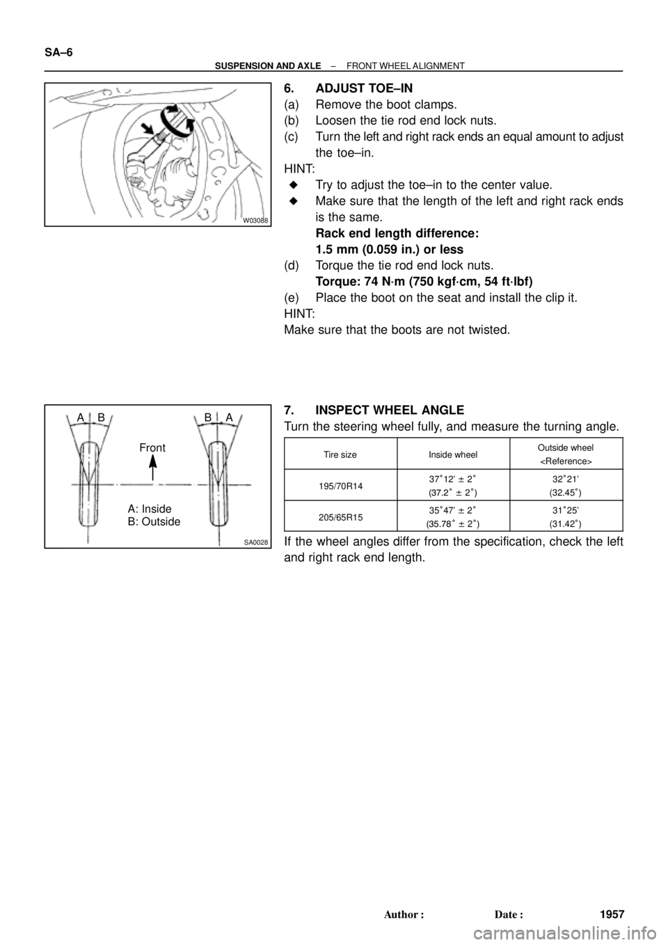
A: Inside
B: Outside AB
Front BA SA±6
± SUSPENSION AND AXLEFRONT WHEEL ALIGNMENT
1957 Author�: Date�:
6. ADJUST TOE±IN
(a) Remove the boot clamps.
(b) Loosen the tie rod end lock nuts.
(c) Turn the left and right rack ends an equal amount to adjust
the toe±in.
HINT:
�Try to adjust the toe±in to the center value.
�Make sure that the length of the left and right rack ends
is the same.
Rack end length difference:
1.5 mm (0.059 in.) or less
(d) Torque the tie rod end lock nuts.
Torque: 74 N´m (750 kgf´cm, 54 ft´lbf)
(e) Place the boot on the seat and install the clip it.
HINT:
Make sure that the boots are not twisted.
7. INSPECT WHEEL ANGLE
Turn the steering wheel fully, and measure the turning angle.
Tire sizeInside wheelOutside wheel
195/70R1437°12' ± 2°
(37.2° ± 2°)32°21'
(32.45°)
205/65R1535°47' ± 2°
(35.78° ± 2°)31°25'
(31.42°)
If the wheel angles differ from the specification, check the left
and right rack end length.