Page 3564 of 4592
W03091
SA±8
± SUSPENSION AND AXLEREAR WHEEL ALIGNMENT
1959 Author�: Date�:
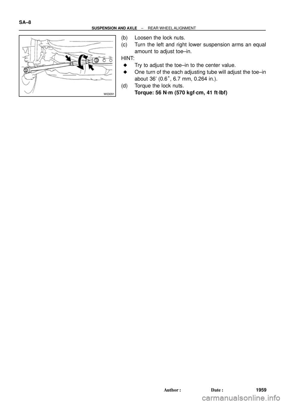
(b) Loosen the lock nuts.
(c) Turn the left and right lower suspension arms an equal
amount to adjust toe±in.
HINT:
�Try to adjust the toe±in to the center value.
�One turn of the each adjusting tube will adjust the toe±in
about 36' (0.6°, 6.7 mm, 0.264 in.).
(d) Torque the lock nuts.
Torque: 56 N´m (570 kgf´cm, 41 ft´lbf)
Page 3566 of 4592

2. CHECK BE")
SA07C±01
W03084W03084
W03093
W03139
W03094
SST
SA±10
± SUSPENSION AND AXLEFRONT AXLE HUB
1961 Author�: Date�:
REMOVAL
1. REMOVE FRONT WHEEL
Torque: 103 N´m (1,050 kgf´cm, 76 ft´lbf)
2. CHECK BEARING BACKLASH AND AXLE HUB DEVI-
ATION
(a) Remove the 2 bolts, brake caliper and disc.
(b) Support the brake caliper securely.
(c) Using a dial indicator near the center of the axle hub and
check the backlash in the bearing shaft direction.
Maximum: 0.05 mm (0.0020 in.)
If the backlash exceeds the maximum, replace the bearing.
(d) Using a dial indicator, check the deviation at the surface
of the axle hub outside the hub bolt.
Maximum: 0.05 mm (0.0020 in.)
If the deviation exceeds the maximum, replace the bearing.
(e) Install the disc, 2 bolts and brake caliper.
Torque: 107 N´m (1,090 kgf´cm, 79 ft´lbf)
3. REMOVE DRIVE SHAFT LOCK NUT
(a) Remove the cotter pin and lock cap.
(b) With applying the brakes, remove the nut.
Torque: 294 N´m (3,000 kgf´cm, 217 ft´lbf)
(c) Remove the brake caliper and disc.
4. w/ ABS:
REMOVE ABS SPEED SENSOR AND WIRE HARNESS
CLAMP
Torque: 8.0 N´m (82 kgf´cm, 71 in.´lbf)
5. LOOSEN 2 NUTS ON LOWER SIDE OF SHOCK AB-
SORBER
Torque: 211 N´m (2,150 kgf´cm, 156 ft´lbf)
HINT:
�Do not remove the bolts.
�At the time of installation, coat the nut's thread with en-
gine oil.
6. DISCONNECT TIE ROD END FROM STEERING
KNUCKLE
(a) Remove the cotter pin and nut.
Torque: 49 N´m (500 kgf´cm, 36 ft´lbf)
(b) Using SST, disconnect the tie rod end from the steering
knuckle.
SST 09610±20012
Page 3571 of 4592
W03096
SST
SA07G±01
W03097
± SUSPENSION AND AXLEFRONT WHEEL HUB BOLT
SA±15
1966 Author�: Date�:
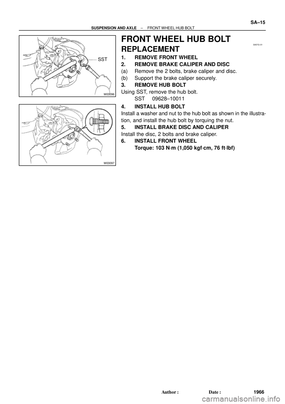
FRONT WHEEL HUB BOLT
REPLACEMENT
1. REMOVE FRONT WHEEL
2. REMOVE BRAKE CALIPER AND DISC
(a) Remove the 2 bolts, brake caliper and disc.
(b) Support the brake caliper securely.
3. REMOVE HUB BOLT
Using SST, remove the hub bolt.
SST 09628±10011
4. INSTALL HUB BOLT
Install a washer and nut to the hub bolt as shown in the illustra-
tion, and install the hub bolt by torquing the nut.
5. INSTALL BRAKE DISC AND CALIPER
Install the disc, 2 bolts and brake caliper.
6. INSTALL FRONT WHEEL
Torque: 103 N´m (1,050 kgf´cm, 76 ft´lbf)
Page 3573 of 4592

SA±17
1968 Author�: Date�:
REMOVAL
NOTICE:
The hub bearing could be damaged if it is subjected to the
vehicle weig")
SA08Q±01
FA1535
SST
W03093
W03142
± SUSPENSION AND AXLEFRONT DRIVE SHAFT (5S±FE)
SA±17
1968 Author�: Date�:
REMOVAL
NOTICE:
The hub bearing could be damaged if it is subjected to the
vehicle weight, such as when moving the vehicle with the
drive shaft removed.
Therefore, if it is absolutely necessary to place the vehicle
weight on the hub bearing, first support it with SST.
SST 09608±16042 (09608±02021, 09608±02041)
1. REMOVE FRONT WHEEL AND FRONT FENDER
APRON SEAL
Torque: 103 N´m (1,050 kgf´cm, 76 ft´lbf)
2. REMOVE DRIVE SHAFT LOCK NUT
(a) Remove the cotter pin and lock cap.
(b) With applying the brakes, remove the nut.
Torque: 294 N´m (3,000 kgf´cm, 217 ft´lbf)
3. DRAIN GEAR OIL (M/T) or ATF (A/T)
4. DISCONNECT TIE ROD END FROM STEERING
KNUCKLE (See page SA±10)
5. DISCONNECT LOWER BALL JOINT FROM LOWER
SUSPENSION ARM (See page SA±10)
6. DISCONNECT DRIVE SHAFT FROM AXLE HUB
(a) Using a plastic hammer, disconnect the drive shaft from
the axle hub.
NOTICE:
Cover the drive shaft boot with cloth to protect it from dam-
age.
(b) Push the front axle hub toward the outside of the vehicle,
and separate the drive shaft from the axle hub.
Page 3590 of 4592

2. REMOVE FLEXIBLE HOSE AN")
SA07N±01
Z19346
To Outside SA±34
± SUSPENSION AND AXLEFRONT SHOCK ABSORBER
1985 Author�: Date�:
REMOVAL
1. REMOVE FRONT WHEEL
Torque: 103 N´m (1,050 kgf´cm, 76 ft´lbf)
2. REMOVE FLEXIBLE HOSE AND ABS SPEED SEN-
SOR WIRE HARNESS (w/ ABS) AND CLAMP FROM
SHOCK ABSORBER
Remove the bolt, flexible hose and ABS wire harness clamp.
Torque: 29 N´m (300 kgf´cm, 22 ft´lbf)
3. DISCONNECT STABILIZER BAR LINK FROM SHOCK
ABSORBER (See page SA±48)
4. DISCONNECT SHOCK ABSORBER FROM STEERING
KNUCKLE
(a) Remove the 2 nuts and bolts on the lower side of the
shock absorber.
Torque: 211 N´m (2,150 kgf´cm, 156 ft´lbf)
(b) Remove the shock absorber from the steering knuckle.
HINT:
At the time of installation, coat the nut's threads with engine oil.
5. REMOVE SHOCK ABSORBER WITH COIL SPRING
Remove the 3 nuts, suspension support No.2 and shock ab-
sorber with the coil spring.
Torque: 80 N´m (820 kgf´cm, 59 ft´lbf)
HINT:
At the time of installation rotate the suspension support and set
it in the direction, as shown in the illustration.
Page 3597 of 4592
SA07U±01
W03202
W03203
W03204
± SUSPENSION AND AXLEFRONT LOWER SUSPENSION ARM
SA±41
1992 Author�: Date�:
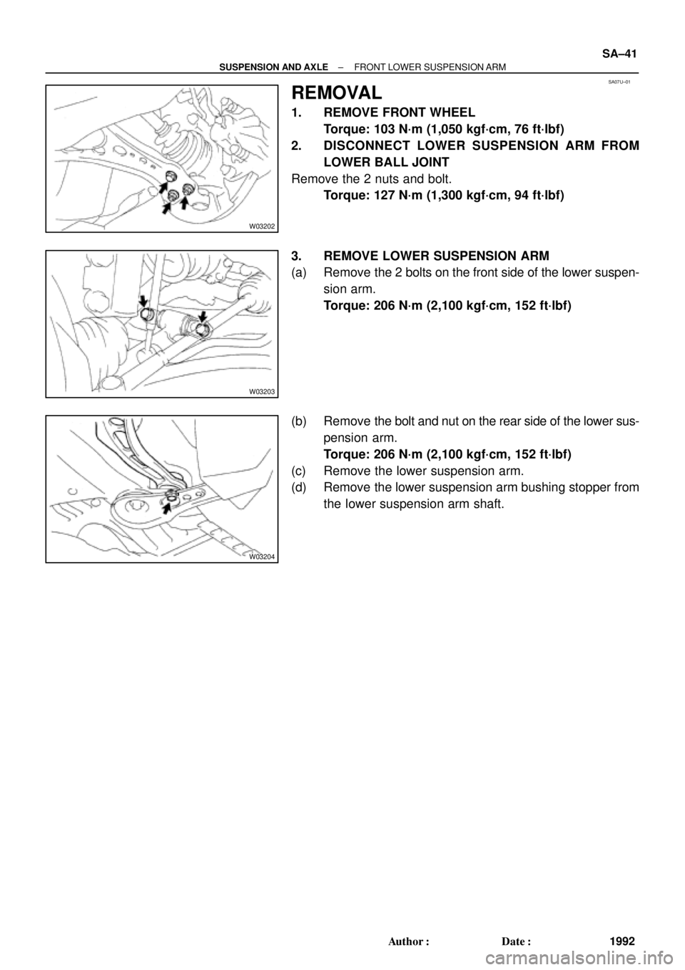
REMOVAL
1. REMOVE FRONT WHEEL
Torque: 103 N´m (1,050 kgf´cm, 76 ft´lbf)
2. DISCONNECT LOWER SUSPENSION ARM FROM
LOWER BALL JOINT
Remove the 2 nuts and bolt.
Torque: 127 N´m (1,300 kgf´cm, 94 ft´lbf)
3. REMOVE LOWER SUSPENSION ARM
(a) Remove the 2 bolts on the front side of the lower suspen-
sion arm.
Torque: 206 N´m (2,100 kgf´cm, 152 ft´lbf)
(b) Remove the bolt and nut on the rear side of the lower sus-
pension arm.
Torque: 206 N´m (2,100 kgf´cm, 152 ft´lbf)
(c) Remove the lower suspension arm.
(d) Remove the lower suspension arm bushing stopper from
the lower suspension arm shaft.
Page 3602 of 4592
SA080±01
R08850
R08861
SST
SST SA±46
± SUSPENSION AND AXLEFRONT LOWER BALL JOINT
1997 Author�: Date�:
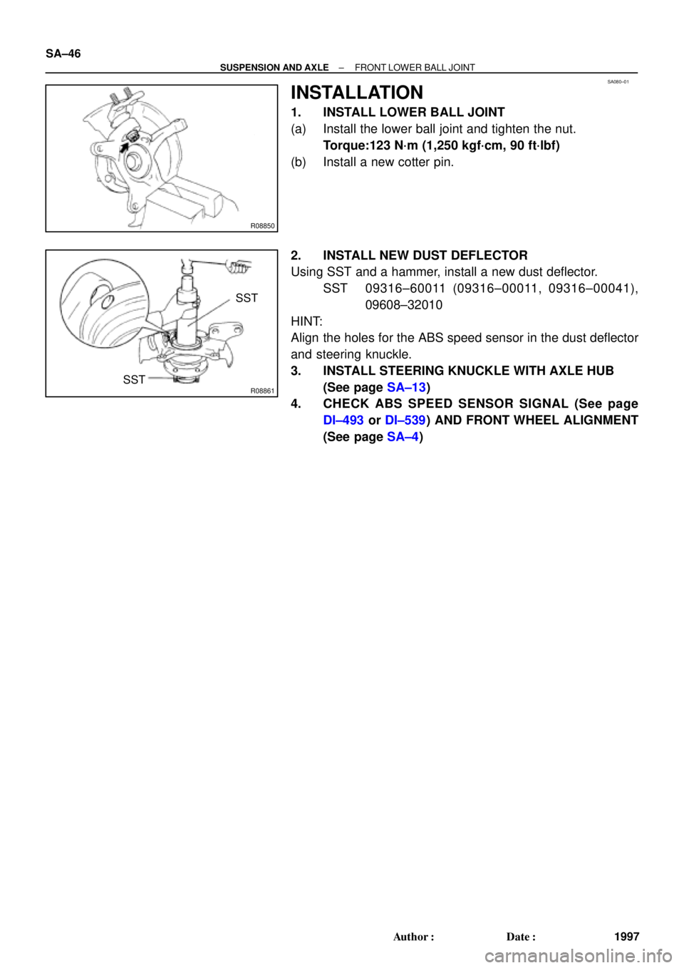
INSTALLATION
1. INSTALL LOWER BALL JOINT
(a) Install the lower ball joint and tighten the nut.
Torque:123 N´m (1,250 kgf´cm, 90 ft´lbf)
(b) Install a new cotter pin.
2. INSTALL NEW DUST DEFLECTOR
Using SST and a hammer, install a new dust deflector.
SST 09316±60011 (09316±00011, 09316±00041),
09608±32010
HINT:
Align the holes for the ABS speed sensor in the dust deflector
and steering knuckle.
3. INSTALL STEERING KNUCKLE WITH AXLE HUB
(See page SA±13)
4. CHECK ABS SPEED SENSOR SIGNAL (See page
DI±493 or DI±539) AND FRONT WHEEL ALIGNMENT
(See page SA±4)
Page 3604 of 4592
SA082±01
W03208
W03209
SA±48
± SUSPENSION AND AXLEFRONT STABILIZER BAR
1999 Author�: Date�:
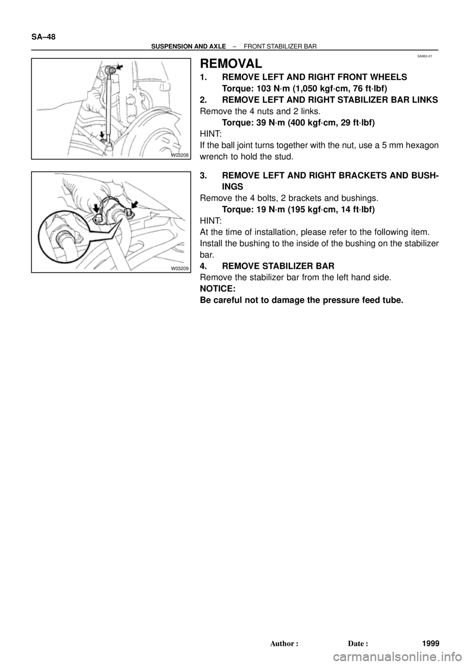
REMOVAL
1. REMOVE LEFT AND RIGHT FRONT WHEELS
Torque: 103 N´m (1,050 kgf´cm, 76 ft´lbf)
2. REMOVE LEFT AND RIGHT STABILIZER BAR LINKS
Remove the 4 nuts and 2 links.
Torque: 39 N´m (400 kgf´cm, 29 ft´lbf)
HINT:
If the ball joint turns together with the nut, use a 5 mm hexagon
wrench to hold the stud.
3. REMOVE LEFT AND RIGHT BRACKETS AND BUSH-
INGS
Remove the 4 bolts, 2 brackets and bushings.
Torque: 19 N´m (195 kgf´cm, 14 ft´lbf)
HINT:
At the time of installation, please refer to the following item.
Install the bushing to the inside of the bushing on the stabilizer
bar.
4. REMOVE STABILIZER BAR
Remove the stabilizer bar from the left hand side.
NOTICE:
Be careful not to damage the pressure feed tube.