Page 2100 of 4592

I00292
Vehicle Speed Sensor
ECUCombination Meter
Cruise Control ECU
4 pulses/
1 rotation
of rotor shaft4 pulses/
1 rotation
of rotor shaft
I00282
Cruise Control ECU
12
SPDV±W V±WB
BJ15
J/CIG3
3
V±W14
Combination Meter
15
6
Speedo
±meter
P L
IJ12IJ17
P
3L
2
SI
SE
IG+
1
R±Lto GAUGE Fuse
C15
C9 C9
C10
Speed
Sensor DI±888
± DIAGNOSTICSCRUISE CONTROL SYSTEM
1123 Author�: Date�:
DTC 21 Open in Vehicle Speed Sensor Circuit
CIRCUIT DESCRIPTION
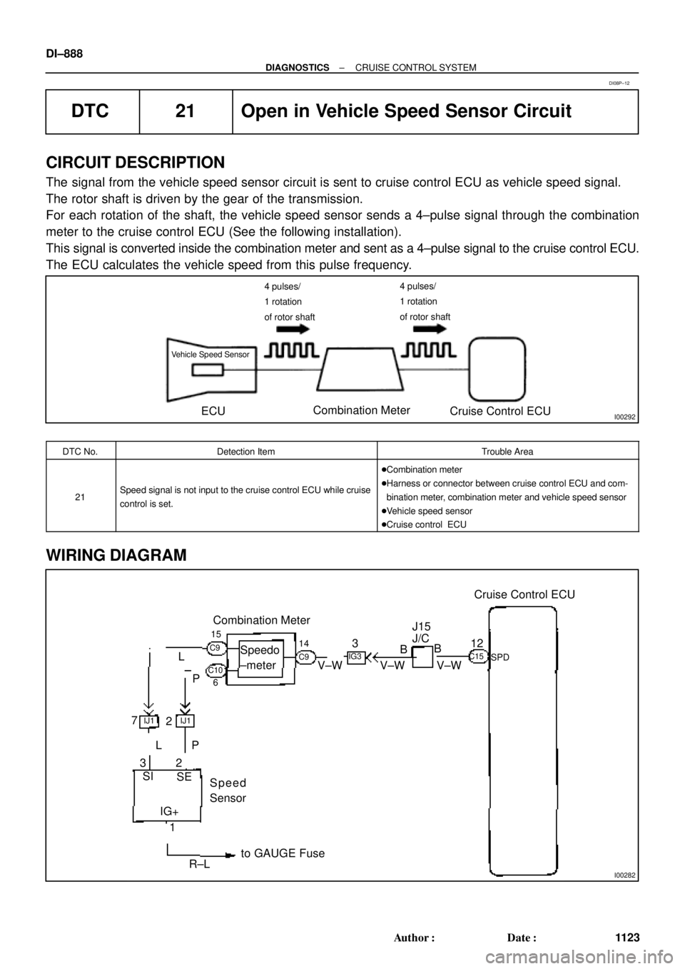
The signal from the vehicle speed sensor circuit is sent to cruise control ECU as vehicle speed signal.
The rotor shaft is driven by the gear of the transmission.
For each rotation of the shaft, the vehicle speed sensor sends a 4±pulse signal through the combination
meter to the cruise control ECU (See the following installation).
This signal is converted inside the combination meter and sent as a 4±pulse signal to the cruise control ECU.
The ECU calculates the vehicle speed from this pulse frequency.
DTC No.Detection ItemTrouble Area
21Speed signal is not input to the cruise control ECU while cruise
control is set.
�Combination meter
�Harness or connector between cruise control ECU and com-
bination meter, combination meter and vehicle speed sensor
�Vehicle speed sensor
�Cruise control ECU
WIRING DIAGRAM
DI08P±12
Page 2103 of 4592
± DIAGNOSTICSCRUISE CONTROL SYSTEM
DI±891
1126 Author�: Date�:
DTC 23 Vehicle Speed Signal Abnormal
CIRCUIT DESCRIPTION
See page DI±888.
DTC No.Detection ItemTrouble Area
23Vehicle speed sensor pulse is abnormal.�Vehicle speed sensor
�Cruise control ECU
WIRING DIAGRAM
See page DI±888.
INSPECTION PROCEDURE
1 Check vehicle speed sensor (See page BE±47).
NG Replace vehicle speed sensor.
OK
Check and replace cruise control ECU
(See page IN±31).
DI08Q±10
Page 2104 of 4592
I00283
Cruise Control ECU
CMS
CCS
GND
CMS
W±L
W±B
W Cruise Control Switch
� Main Switch
� Control Switch
1J
78
W±B5
4
3
W±B MAIN
CANCEL
SET/COAST
RES/ACC
A11
10
16 CCS
EP
J7
J7J8 AJ/C
A
A
1J
W±B J/C
IGC15
C15
C15
J11
Instrument Panel J/B DI±892
± DIAGNOSTICSCRUISE CONTROL SYSTEM
1127 Author�: Date�:
DTC 32 Control Switch Circuit (Cruise Control
Switch)
CIRCUIT DESCRIPTION
This circuit carries the SET/COAST, RESUME/ACCEL and CANCEL signals (each voltage) to the ECU.
DTC No.Detection ItemTrouble Area
32Short in control switch circuit.
�Cruise control switch
�Harness or connector between cruise control ECU and
cruise control switch, cruise control switch and body ground
�Cruise control ECU
WIRING DIAGRAM
DI08R±12
Page 2107 of 4592
I00284
Cruise Control ECU
IDL 13
L±R *
2*1
ECM
IDL
*
1: 5S±FE Engine
*2: 1MZ±FE Engine E7 E8
C15
34
± DIAGNOSTICSCRUISE CONTROL SYSTEM
DI±895
1130 Author�: Date�:
DTC 51 Idle Signal Circuit
CIRCUIT DESCRIPTION
When the idle switch is turned ON, a signal is sent to the ECU. The ECU uses this signal to correct the dis-
crepancy between the throttle valve position and the actuator position sensor value to enable accurate
cruise control at the set speed. If the idle switch is malfunctioning, problem symptoms also occur in the en-
gine, so also inspect the engine.
DTC No.Detection ItemTrouble Area
51Short in idle signal circuit.
�Harness or connector between ECM and throttle position
sensor
�Throttle position sensor
�Harness or connector between cruise control ECU and ECM
�Cruise control ECU
WIRING DIAGRAM
DI08S±10
Page 2110 of 4592

I00285
Cruise Control ECU
2
STP±
8
L
J27
J/C
G±W A A
G±W 5
1R
1R
G±W 1
4 Stop Light Switch
2
3
W
7
1C4
1BG±B 4
B±R
FL BLOCK
F91 1
F4
B±G
FL MAIN
BatteryR±Y
Cruise Control
Actuator
3
4 J/C
A
J7 A
J7
W±B
1J
1JJ/C
AJ11
W±B
IG Instrument Panel J/B
STOP
ALT
C15
C15
Instrument Panel J/B
Instrument Panel J/BW±B
87 DI±898
± DIAGNOSTICSCRUISE CONTROL SYSTEM
1133 Author�: Date�:
Stop Light Switch Circuit
CIRCUIT DESCRIPTION
When the brake pedal is depressed, the stop light switch sends a signal to the ECU. When the ECU receives
this signal, it cancels the cruise control.
A fail±safe function is provided so that the cancel functions normally, even if there is a malfunction in the stop
light signal circuit.
The cancel conditions are: Battery positive voltage at terminal STP±
When the brake is ON, battery positive voltage normally is applied through the STOP fuse and stop light
switch to terminal STP± of the ECU, and the ECU turns the cruise control OFF.
If the harness connected to terminal STP± has an open circuit, terminal STP± will have battery positive volt-
age and the cruise control will be turned OFF.
Also, when the brake is ON, the magnetic clutch circuit is cut mechanically by the stop light switch, turning
the cruise control OFF. (See page DI±883 for operation of the magnetic clutch)
WIRING DIAGRAM
DI08T±11
Page 2113 of 4592

I08432
S2OD 14Cruise Control ECU *1: 1MZ±FE
*2: 5S±FE (w/ Immobiliser)
*3: 5S±FE (w/o Immobiliser)
ECT No.2
SolenoidECT C15
6
C15 Y±B
L±B ECM
24 18 20
E8 E7 E7
*1 *2 *3 OD1
8216
E11
E9 E9
*1 *2 *3L±B L±B7
II2 J26
*1
J25*2
J/C
A
AA
± DIAGNOSTICSCRUISE CONTROL SYSTEM
DI±901
1136 Author�: Date�:
Electronically Controlled Transmission Communication Circuit
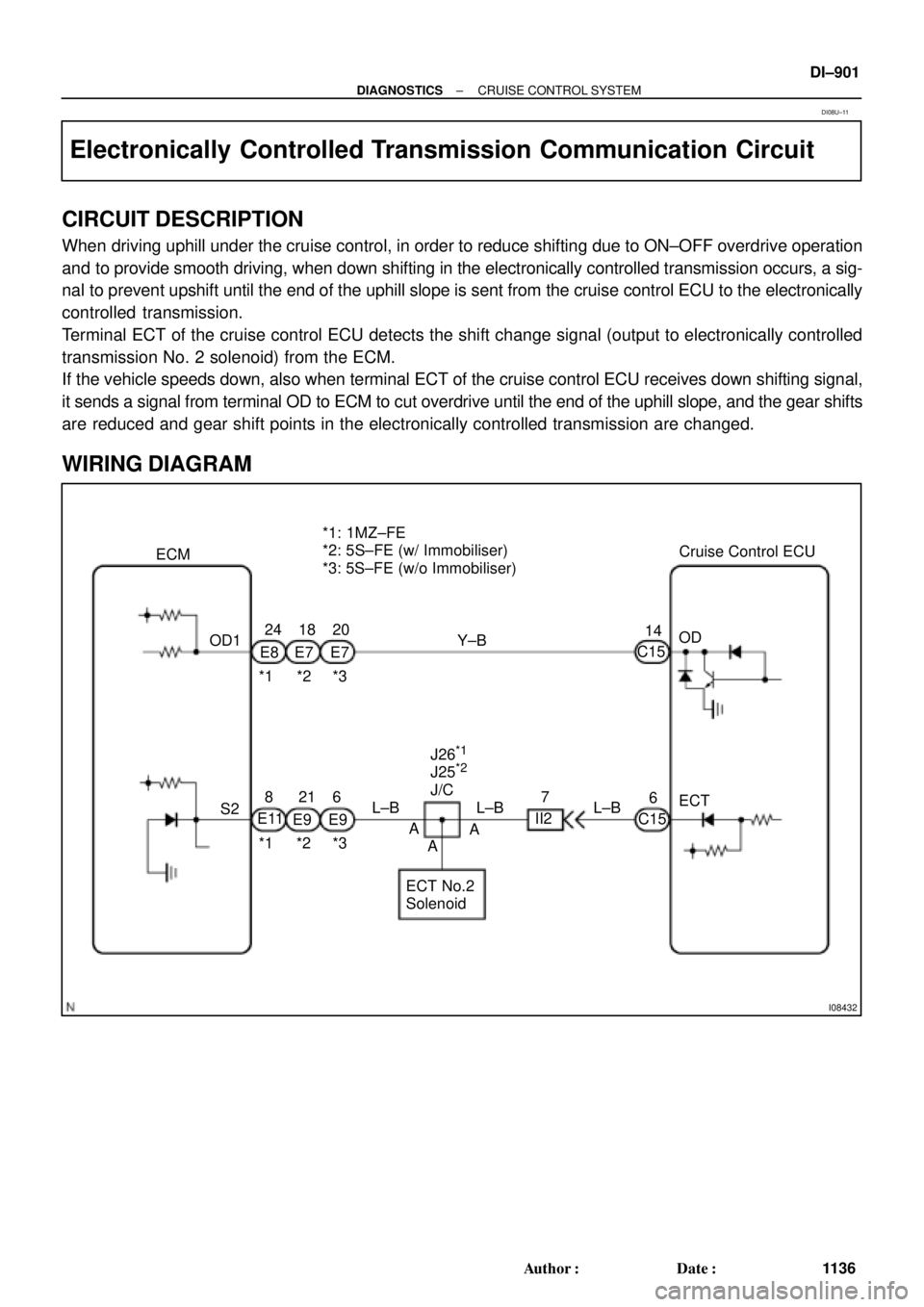
CIRCUIT DESCRIPTION
When driving uphill under the cruise control, in order to reduce shifting due to ON±OFF overdrive operation
and to provide smooth driving, when down shifting in the electronically controlled transmission occurs, a sig-
nal to prevent upshift until the end of the uphill slope is sent from the cruise control ECU to the electronically
controlled transmission.
Terminal ECT of the cruise control ECU detects the shift change signal (output to electronically controlled
transmission No. 2 solenoid) from the ECM.
If the vehicle speeds down, also when terminal ECT of the cruise control ECU receives down shifting signal,
it sends a signal from terminal OD to ECM to cut overdrive until the end of the uphill slope, and the gear shifts
are reduced and gear shift points in the electronically controlled transmission are changed.
WIRING DIAGRAM
DI08U±11
Page 2116 of 4592
I08433
Cruise Control ECU
Instrument Panel J/B
Clutch Switch
PNP Switch GAUGE
1K
D 3 J29
J/C
J/C
J21 (5S±FE)
J24 (1MZ±FE) B±Y1JC15 For M/T
J/C
B±R A
A
A B±R
R±L R±L
2
1 D
J27 F
J28
F J28
R±L
R±L 2
II2
A
A
R±L210
B±R9
II2For A/T
FL BLOCK IG1
Battery Ignition Switch
2
4AM1
Instrument Panel J/B
AM1
1B1
1K2W
B±R
F91
F41
ALT
B±G
FL MAIN 11 DI±904
± DIAGNOSTICSCRUISE CONTROL SYSTEM
1139 Author�: Date�:
Park/Neutral Position Switch Circuit
CIRCUIT DESCRIPTION
When the shift position is except D, a signal is sent from the park/neutral position switch to the ECU. When
this signal is input during cruise control driving, the ECU cancels the cruise control.
WIRING DIAGRAM
DI08V±11
Page 2119 of 4592

Input Signal
Indicator Light
Blinking Pattern
Clutch switch
OFF (Depress
clutch pedal)
LightON
OFFSW ON
SW OFF
± DIAGNOSTICSCRUISE CONTROL SYSTEM
DI±907
1142 Author�: Date�:
Clutch Switch Circuit
CIRCUIT DESCRIPTION
When the clutch pedal is depressed, the clutch switch sends a signal to the cruise control ECU. When the
signal is input to the cruise control ECU during cruise control driving, the cruise control ECU cancels cruise
control.
WIRING DIAGRAM
Refer to PNP switch circuit on page DI±904.
INSPECTION PROCEDURE
1 Check starter operation.
CHECK:
Check that the starter operates normally and that the engine starts.
NG Proceed to engine troubleshooting
(5S±FE: See page ST±1)
(1MZ±FE: See page ST±1).
OK
2 Input signal check.
PREPARATION:
See input signal check on page DI±870.
CHECK:
Check the indicator lights when clutch pedal is depressed.
OK:
The indicator light goes off when shifting into clutch
pedal is depressed.
OK Proceed to next circuit inspection shown on
problem symptoms table (See page DI±879).
NG
DI08W±04