Page 2121 of 4592

LightON
OFFSW ON
SW OFF
± DIAGNOSTICSCRUISE CONTROL SYSTEM
DI±907
1142 Author�: Date�:
Clutch Switch Circuit
C")
Input Signal
Indicator Light
Blinking Pattern
Clutch switch
OFF (Depress
clutch pedal)
LightON
OFFSW ON
SW OFF
± DIAGNOSTICSCRUISE CONTROL SYSTEM
DI±907
1142 Author�: Date�:
Clutch Switch Circuit
CIRCUIT DESCRIPTION
When the clutch pedal is depressed, the clutch switch sends a signal to the cruise control ECU. When the
signal is input to the cruise control ECU during cruise control driving, the cruise control ECU cancels cruise
control.
WIRING DIAGRAM
Refer to PNP switch circuit on page DI±904.
INSPECTION PROCEDURE
1 Check starter operation.
CHECK:
Check that the starter operates normally and that the engine starts.
NG Proceed to engine troubleshooting
(5S±FE: See page ST±1)
(1MZ±FE: See page ST±1).
OK
2 Input signal check.
PREPARATION:
See input signal check on page DI±870.
CHECK:
Check the indicator lights when clutch pedal is depressed.
OK:
The indicator light goes off when shifting into clutch
pedal is depressed.
OK Proceed to next circuit inspection shown on
problem symptoms table (See page DI±879).
NG
DI08W±04
Page 2123 of 4592
I08434
Instrument Panel J/B
Ignition Switch
ECU±IG
B 9 J12
J/C
B±YC15
B±R C
C
GND
IG1
2
B±R IG1
Battery24
AM1
Instrument Panel J/B
AM1 1K1
W
B±GF9
F41
W±B
FL MAINCruise Control ECU
1J9
B±R
1K
1B1
16
C15
W±B
W±BJ8A
J7AJ/C
1J8
1J7Instrument Panel J/B
A J11
J/C FL BLOCK
ALT
± DIAGNOSTICSCRUISE CONTROL SYSTEM
DI±909
1144 Author�: Date�:
ECU Power Source Circuit
CIRCUIT DESCRIPTION
The ECU power source supplies power to the actuator and sensors, etc, when terminal GND and the cruise
control ECU case are grounded.
WIRING DIAGRAM
DI08X±11
Page 2126 of 4592
AB0119
I00145
I00177
ON
CMS
(±) (+)
DI±912
± DIAGNOSTICSCRUISE CONTROL SYSTEM
1147 Author�: Date�:
Main Switch Circuit (Cruise Control Switch)
CIRCUIT DESCRIPTION
When the cruise control main switch is turned OFF, the cruise control does not operate.
WIRING DIAGRAM
See page DI±892.
INSPECTION PROCEDURE
1 Check voltage between terminal CMS of cruise control ECU connector and body
ground.
PREPARATION:
(a) Remove the ECU with connector still connected.
(b) Turn ignition switch ON.
CHECK:
Measure voltage between terminal CMS of cruise control ECU
connector when main switch is held ON and OFF.
OK:
Main switchVoltage
OFF10 ± 14 V
ONBelow 0.5 V
OK Proceed to next circuit inspection shown on
problem symptoms table (See page DI±879).
NG
DI08Z±16
Page 2128 of 4592
I00290
Cruise Control ECU
4
PI
O D DJ/C
O IG25
O 10
7
R±L D DJ/C
R±L
Instrument Panel J/B
2
1D
1K1
B±Y4IG1AM1 Ignition Switch
2
W
Instrument Panel J/B
AM1 GAUGE
2
1K 1
1B
B±R 1
ALT FL BLOCK
1
B±G
FL MAIN
BatteryCRUISE MAIN
Indicator Light
(in Combination Meter)
C15
J2
C10
C10 J4
F9
F4 DI±914
± DIAGNOSTICSCRUISE CONTROL SYSTEM
1149 Author�: Date�:
CRUISE MAIN Indicator Light Circuit
CIRCUIT DESCRIPTION
When the cruise control main switch is turned ON, CRUISE MAIN indicator light lights up.
WIRING DIAGRAM
DI090±17
Page 2130 of 4592
I00291
Cruise Control ECU
4
PI
5
TC O
LG±R D DJ/C
J/C
B
B B O
LG±R 10
4DLC2
II3 11
C15
LG±R*1
11 DLC1
C15
J2
D4 D4
J3
D1LG±R
P±B
*2
*1: TMC Made, TMMK Made (5S±FE)
*2: TMMK Made (1MZ±FE) DI±916
± DIAGNOSTICSCRUISE CONTROL SYSTEM
1151 Author�: Date�:
Diagnosis Circuit
CIRCUIT DESCRIPTION
This circuit sends a signal to the ECU that outputs DTC.
WIRING DIAGRAM
DI091±11
Page 2143 of 4592
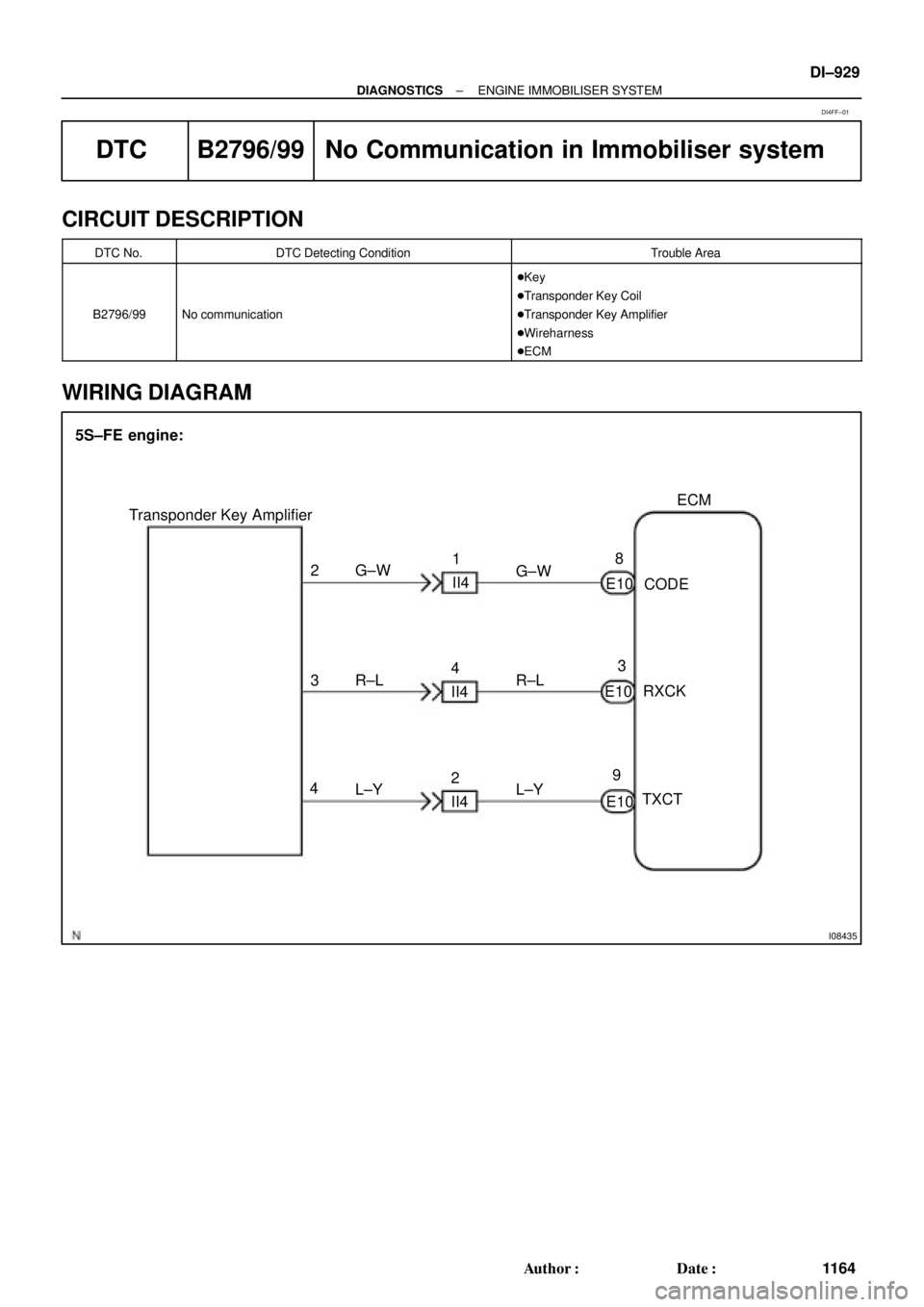
I08435
ECM
E10 28
93
E10
E10 3
4G±W
R±L
L±Y Transponder Key Amplifier
CODE
RXCK
TXCT 5S±FE engine:
G±W
R±L
L±Y 1
II4
4
II4
2
II4
± DIAGNOSTICSENGINE IMMOBILISER SYSTEM
DI±929
1164 Author�: Date�:
DTC B2796/99 No Communication in Immobiliser system
CIRCUIT DESCRIPTION
DTC No.DTC Detecting ConditionTrouble Area
B2796/99No communication
�Key
�Transponder Key Coil
�Transponder Key Amplifier
�Wireharness
�ECM
WIRING DIAGRAM
DI4FF±01
Page 2146 of 4592
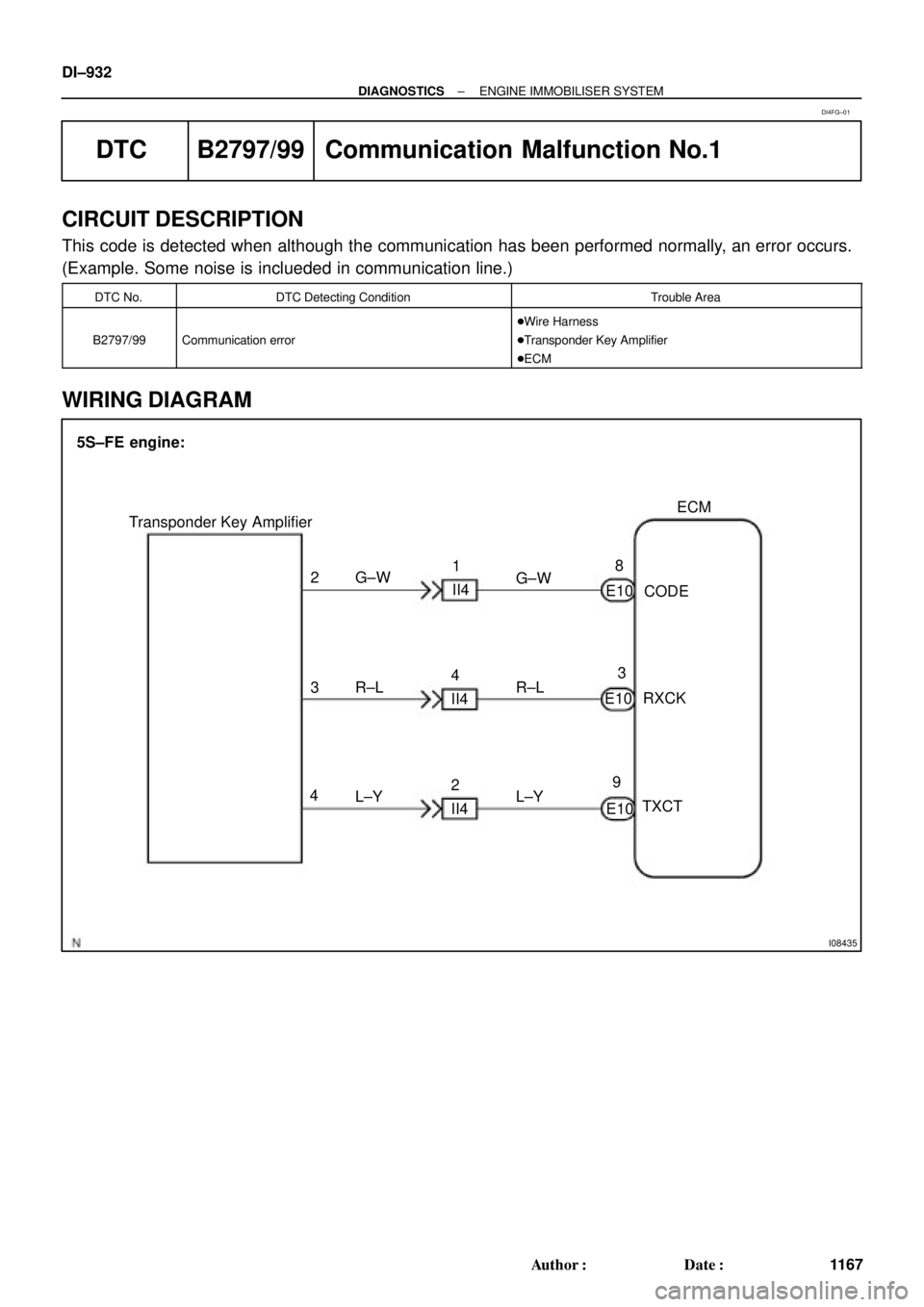
I08435
ECM
E10 28
93
E10
E10 3
4G±W
R±L
L±Y Transponder Key Amplifier
CODE
RXCK
TXCT 5S±FE engine:
G±W
R±L
L±Y 1
II4
4
II4
2
II4 DI±932
± DIAGNOSTICSENGINE IMMOBILISER SYSTEM
1167 Author�: Date�:
DTC B2797/99 Communication Malfunction No.1
CIRCUIT DESCRIPTION
This code is detected when although the communication has been performed normally, an error occurs.
(Example. Some noise is inclueded in communication line.)
DTC No.DTC Detecting ConditionTrouble Area
B2797/99Communication error
�Wire Harness
�Transponder Key Amplifier
�ECM
WIRING DIAGRAM
DI4FG±01
Page 2149 of 4592
I08435
ECM
E10 28
93
E10
E10 3
4G±W
R±L
L±Y Transponder Key Amplifier
CODE
RXCK
TXCT 5S±FE engine:
G±W
R±L
L±Y 1
II4
4
II4
2
II4
± DIAGNOSTICSENGINE IMMOBILISER SYSTEM
DI±935
1170 Author�: Date�:
DTC B2798/99 Communication malfunction No.2
CIRCUIT DESCRIPTION
DTC No.DTC Detecting ConditionTrouble Area
B2798/99Communication error
�Key
�Transponder Key Coil
�Transponder Key Amplifier
�Wireharness
�ECM
WIRING DIAGRAM
DI4FH±01


*2: TMMK Made (1MZ±FE) DI±91")