Page 2205 of 4592
A09428
(Fig.1)
Acceptable
Resistance kW
± 20 0 20 40 60 80 100
(± 4) (32) (68) (104) (140) (176) (212) 30
20
10
5
3
2
1
0.5
0.3
0.2
0.1
Te m p .°C (F°)
A00310
E7
E56
9ECM
5 V
THCNG2
E2
E1 R
BR 2
1 Fuel Temperature Sensor
for Delivery Pipe
P±B DI±54
± DIAGNOSTICSENGINE
DTC P0180 Fuel Temperature Sensor ºAº Circuit Mal-
function
CIRCUIT DESCRIPTION
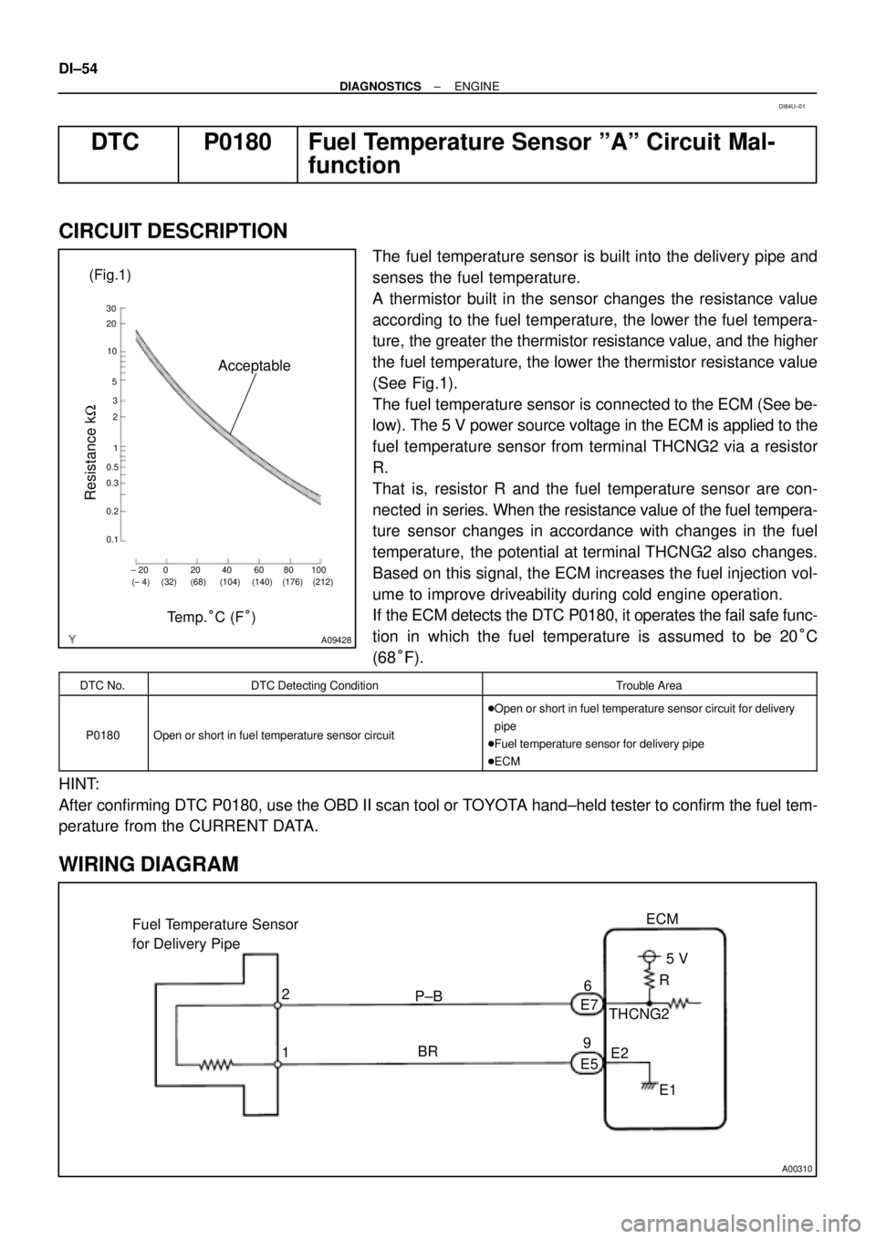
The fuel temperature sensor is built into the delivery pipe and
senses the fuel temperature.
A thermistor built in the sensor changes the resistance value
according to the fuel temperature, the lower the fuel tempera-
ture, the greater the thermistor resistance value, and the higher
the fuel temperature, the lower the thermistor resistance value
(See Fig.1).
The fuel temperature sensor is connected to the ECM (See be-
low). The 5 V power source voltage in the ECM is applied to the
fuel temperature sensor from terminal THCNG2 via a resistor
R.
That is, resistor R and the fuel temperature sensor are con-
nected in series. When the resistance value of the fuel tempera-
ture sensor changes in accordance with changes in the fuel
temperature, the potential at terminal THCNG2 also changes.
Based on this signal, the ECM increases the fuel injection vol-
ume to improve driveability during cold engine operation.
If the ECM detects the DTC P0180, it operates the fail safe func-
tion in which the fuel temperature is assumed to be 20°C
(68°F).
DTC No.DTC Detecting ConditionTrouble Area
P0180Open or short in fuel temperature sensor circuit
�Open or short in fuel temperature sensor circuit for delivery
pipe
�Fuel temperature sensor for delivery pipe
�ECM
HINT:
After confirming DTC P0180, use the OBD II scan tool or TOYOTA hand±held tester to confirm the fuel tem-
perature from the CURRENT DATA.
WIRING DIAGRAM
DI64U±01
Page 2207 of 4592
A00309
ECM Fuel Pressure Sensor
for Delivery Pipe
1PCNG2VC
E2 Y
G±BE5
E7
E5 3
25 V
E1 1
5
9
BR DI±56
± DIAGNOSTICSENGINE
DTC P0190 Fuel Rail Pressure Circuit Malfunction
CIRCUIT DESCRIPTION
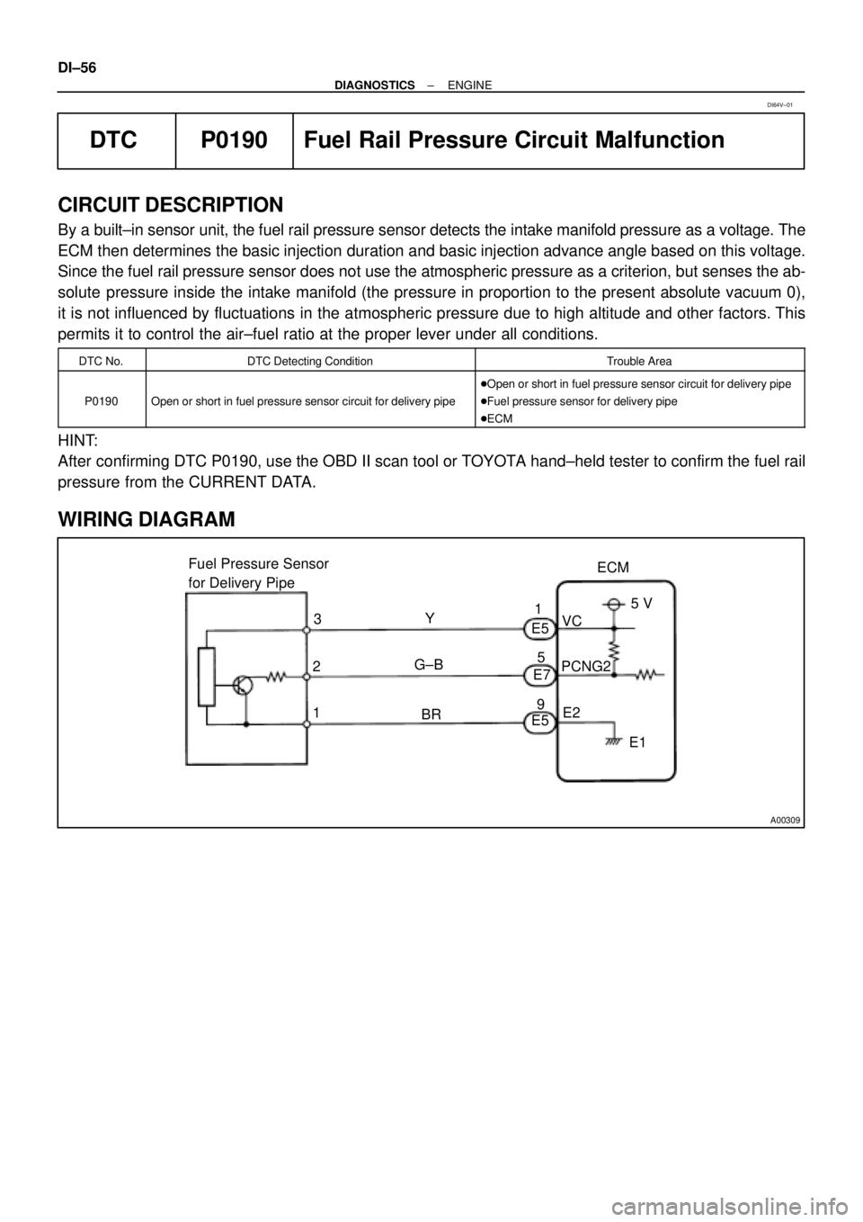
By a built±in sensor unit, the fuel rail pressure sensor detects the intake manifold pressure as a voltage. The
ECM then determines the basic injection duration and basic injection advance angle based on this voltage.
Since the fuel rail pressure sensor does not use the atmospheric pressure as a criterion, but senses the ab-
solute pressure inside the intake manifold (the pressure in proportion to the present absolute vacuum 0),
it is not influenced by fluctuations in the atmospheric pressure due to high altitude and other factors. This
permits it to control the air±fuel ratio at the proper lever under all conditions.
DTC No.DTC Detecting ConditionTrouble Area
P0190Open or short in fuel pressure sensor circuit for delivery pipe
�Open or short in fuel pressure sensor circuit for delivery pipe
�Fuel pressure sensor for delivery pipe
�ECM
HINT:
After confirming DTC P0190, use the OBD II scan tool or TOYOTA hand±held tester to confirm the fuel rail
pressure from the CURRENT DATA.
WIRING DIAGRAM
DI64V±01
Page 2210 of 4592
A09394
ECM
G
NE+
NE±
E1 E6
E6
E65
4
17 B±W
L
B±R
L BR Camshaft Position Sensor
Crankshaft Position Sensor1
2
1
2B±R
± DIAGNOSTICSENGINE
DI±59
DTC P0335 Crankshaft Position Sensor ºAº Circuit Mal-
function
CIRCUIT DESCRIPTION
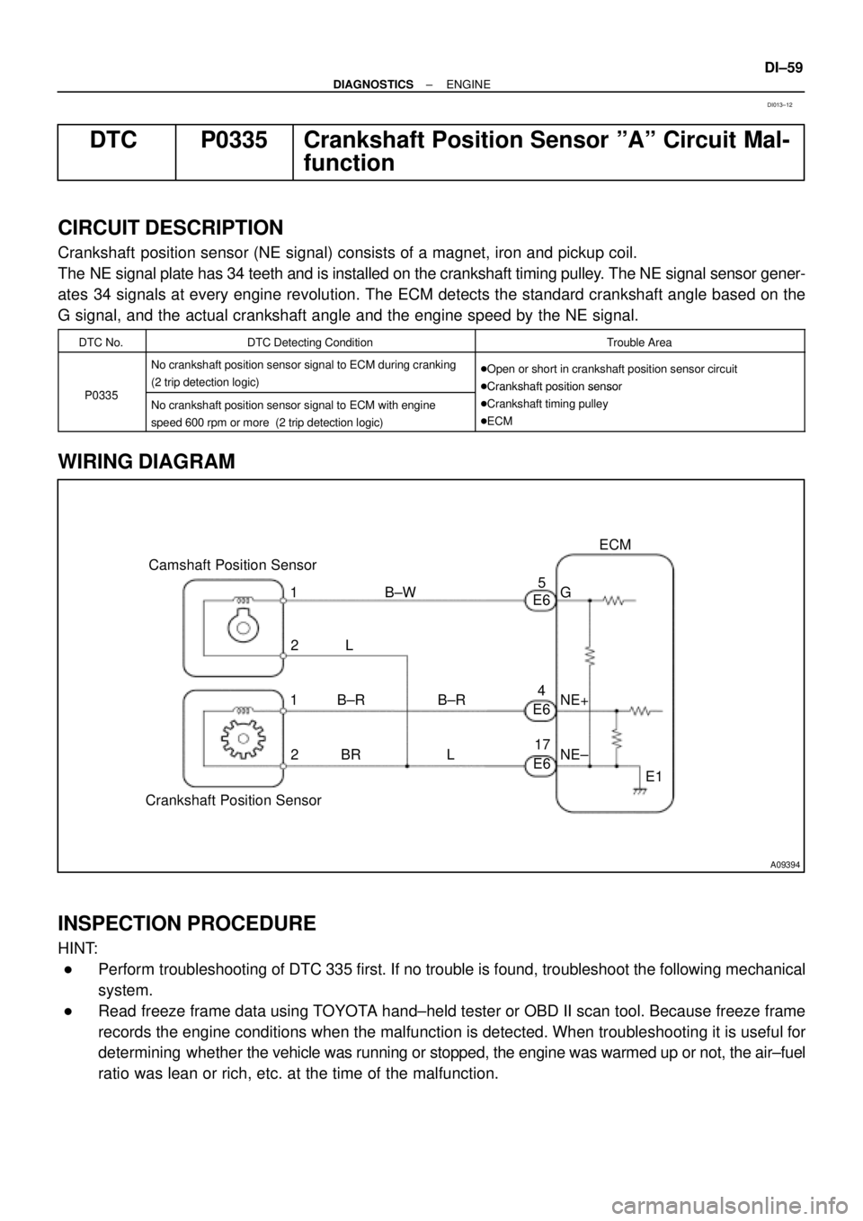
Crankshaft position sensor (NE signal) consists of a magnet, iron and pickup coil.
The NE signal plate has 34 teeth and is installed on the crankshaft timing pulley. The NE signal sensor gener-
ates 34 signals at every engine revolution. The ECM detects the standard crankshaft angle based on the
G signal, and the actual crankshaft angle and the engine speed by the NE signal.
DTC No.DTC Detecting ConditionTrouble Area
P0335
No crankshaft position sensor signal to ECM during cranking
(2 trip detection logic)�Open or short in crankshaft position sensor circuit
�Crankshaft position sensor
P0335No crankshaft position sensor signal to ECM with engine
speed 600 rpm or more (2 trip detection logic)
�Crankshaft osition sensor
�Crankshaft timing pulley
�ECM
WIRING DIAGRAM
INSPECTION PROCEDURE
HINT:
�Perform troubleshooting of DTC 335 first. If no trouble is found, troubleshoot the following mechanical
system.
�Read freeze frame data using TOYOTA hand±held tester or OBD II scan tool. Because freeze frame
records the engine conditions when the malfunction is detected. When troubleshooting it is useful for
determining whether the vehicle was running or stopped, the engine was warmed up or not, the air±fuel
ratio was lean or rich, etc. at the time of the malfunction.
DI013±12
Page 2212 of 4592

± DIAGNOSTICSENGINE
DI±61
DTC P0340 Camshaft Position Sensor Circuit Malfunc-
tion
CIRCUIT DESCRIPTION
Camshaft position sensor (G signal) consists of magnet, iron core and pickup coil.
The G signal plate has one tooth on its outer circumference and is installed on the camshaft timing pulley.
When the camshafts rotate, the protrusion on the signal plate and the air gap on the pickup coil change,
causing fluctuations in the magnetic field and generating an electromotive force in the pickup coil.
The NE signal plate has 34 teeth and is installed on the crankshaft timing pulley. The NE signal sensor gener-
ates 34 signals at every engine revolution. The ECM detects the standard crankshaft angle based on the
G signal and the actual crankshaft angle and the engine speed by the NE signal.
DTC No.DTC Detecting ConditionTrouble Area
P0340
No camshaft position sensor signal to ECM during cranking
(2 trip detection logic)�Open or short in camshaft position sensor circuit
�Camshaft position sensor
P0340No camshaft position sensor signal to ECM with engine speed
600 rpm or more
�Camshaft osition sensor
�Camshaft timing pulley
�ECM
WIRING DIAGRAM
Refer to DTC P0335 on page DI±59.
INSPECTION PROCEDURE
HINT:
Read freeze frame data using TOYOTA hand±held tester or OBD II scan tool. Because freeze frame records
the engine conditions when the malfunction is detected. When troubleshooting it is useful for determining
whether the vehicle was running or stopped, the engine was warmed up or not, the air±fuel ratio was lean
or rich, etc. at the time of the malfunction.
1 Check resistance of camshaft position sensor (See Pub. No. RM654U, page
IG±1).
Reference: INSPECTION USING OSCILLOSCOPE
Refer to DTC P0335 on page DI±59.
NG Replace camshaft position sensor.
OK
2 Check for open and short in harness and connector between ECM and camshaft
position sensor (See page IN±29).
NG Repair or replace harness or connector.
DI014±11
Page 2215 of 4592
A09397
ECM
J18
J/C
7 From
Battery
B
213
EFI Relay VSV
for EGR
21P-B23
E6EGR
E01
2K2
2J EFI
Engine Room J/B No.2 1B 9
B-Y
B
2AB-Y
IG3
EB
W-B
2F4B-Y
5
B-YFrom
Ignition SW
P20769
Vehicle Speed
60 ± 80 km/h
(38 ± 50 mph)
Idling
IG SW OFF
(1)(2)
Warm up
3 ± 5 min.2 min.
3 ± 5 min.Time (3)
(4)
(5)(6)
(7)
2 min. DI±64
± DIAGNOSTICSENGINE
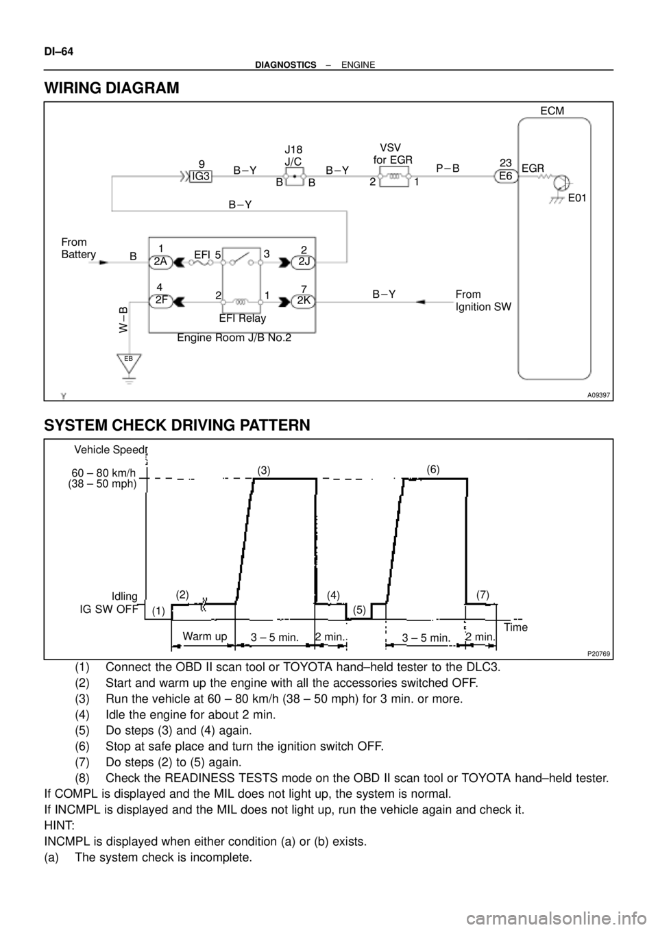
WIRING DIAGRAM
SYSTEM CHECK DRIVING PATTERN
(1) Connect the OBD II scan tool or TOYOTA hand±held tester to the DLC3.
(2) Start and warm up the engine with all the accessories switched OFF.
(3) Run the vehicle at 60 ± 80 km/h (38 ± 50 mph) for 3 min. or more.
(4) Idle the engine for about 2 min.
(5) Do steps (3) and (4) again.
(6) Stop at safe place and turn the ignition switch OFF.
(7) Do steps (2) to (5) again.
(8) Check the READINESS TESTS mode on the OBD II scan tool or TOYOTA hand±held tester.
If COMPL is displayed and the MIL does not light up, the system is normal.
If INCMPL is displayed and the MIL does not light up, run the vehicle again and check it.
HINT:
INCMPL is displayed when either condition (a) or (b) exists.
(a) The system check is incomplete.
Page 2220 of 4592
A00414
Vehicle
Speed Sensor4±Pulse 4±Pulse
Combination Meter
ECM
Transaxle
Vehicle Speed Sensor
A09398
Combination Meter
14
V±WV±W
B J15
J/C
IF1
BV±W9
SPD5 V ECM
3
C11E4
± DIAGNOSTICSENGINE
DI±69
DTC P0500 Vehicle Speed Sensor Malfunction
CIRCUIT DESCRIPTION
The No.1 vehicle speed sensor outputs a 4±pulse signal for every revolution of the rotor shaft, which is ro-
tated by the transmission output shaft via the driven gear. After this signal is converted into a more precise
rectangular waveform by the waveform shaping circuit inside the combination meter, it is then transmitted
to the ECM. The ECM determines the vehicle speed based on the frequency of these pulse signals.
DTC No.DTC Detecting ConditionTrouble Area
P0500During vehicle is being driven, no vehicle speed sensor signal
to ECM (2 trip detection logic)
�Combination meter
�Open or short in vehicle speed sensor circuit
�Vehicle speed sensor
�ECM
WIRING DIAGRAM
DI01B±12
Page 2223 of 4592
A01758
Throttle Valve
To Cylinder ECM SignalFrom
Air
Cleaner
Valve
IAC Valve
Intake Air
Chamber
A09420
Driver Side J/BEFI Relay
Engine Room R/B No.2 From
IG SwitchFrom
BatteryECM
E6 10
w
1
3 2 IAC Valve
B±Y
IG39
EB
B±Y
W±B 4
12 3 5 21EFI
B
37
1W 1KIGN
B±R
W±B
EC
RSD
7 12
2A
2J
2K
2FJ18
J/C
B B
DI±72
± DIAGNOSTICSENGINE
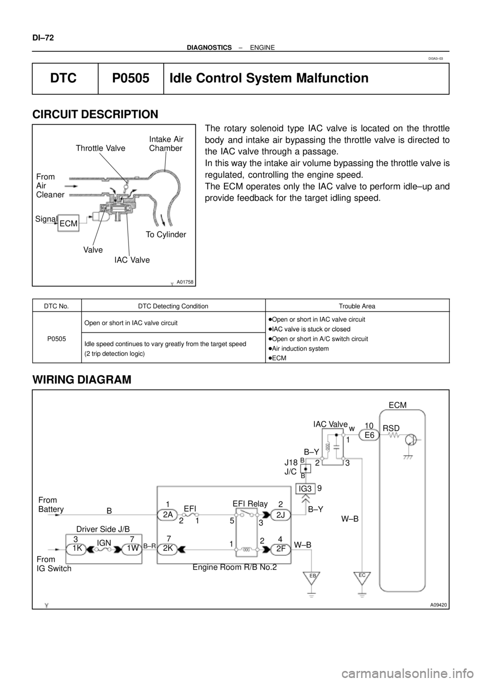
DTC P0505 Idle Control System Malfunction
CIRCUIT DESCRIPTION
The rotary solenoid type IAC valve is located on the throttle
body and intake air bypassing the throttle valve is directed to
the IAC valve through a passage.
In this way the intake air volume bypassing the throttle valve is
regulated, controlling the engine speed.
The ECM operates only the IAC valve to perform idle±up and
provide feedback for the target idling speed.
DTC No.DTC Detecting ConditionTrouble Area
Open or short in IAC valve circuit�Open or short in IAC valve circuit
�IAC valve is stuck or closed
P0505Idle speed continues to vary greatly from the target speed
(2 trip detection logic)
�IAC valve is stuck or closed
�Open or short in A/C switch circuit
�Air induction system
�ECM
WIRING DIAGRAM
DI3A3±03
Page 2230 of 4592

A00364
Vehicle Speed
60 ± 120 km/h
(38 ± 75 mph)
Idling
IG SW OFF
3 ± 5 min.
Time
(1)(2)(4)
(3)
± DIAGNOSTICSENGINE
DI±79
DTC P1130 A/F Sensor Circuit Range/Performance Mal-
function (Bank 1 Sensor 1)
CIRCUIT DESCRIPTION
Refer to DTC P0125 on page DI±40.
DTC No.DTC Detecting ConditionTrouble Area
Voltage output* of A/F sensor remains at 4.5 V or more, during
engine running after engine is warmed up (2 trip detection log-
ic)
*: Output value changes at the inside of ECM only
�Open or short in A/F sensor circuit
�A/F sensor
�
Air induction system
P1130Voltage output* of A/F sensor does not change from 3.30 V,
during engine running after engine is warmed up (2 trip detec-
tion logic)
*: Output value changes at inside of ECM only
�Air induction system
�EGR system
�Fuel pressure
�Injector
�ECM
Open or short in A/F sensor circuit (2 trip detection logic)
HINT:
�After confirming DTC P1130, use the OBD II scan tool or TOYOTA hand-held tester to confirm voltage
output of the A/F sensor (AFS B1 S1/O2S B1 S1) from the CURRENT DATA.
�The A/F sensor's output voltage and the short-term fuel trim value can be read using the OBD II scan
tool or TOYOTA hand-held tester.
�The ECM controls the voltage of the AF+ and AF± terminals of the ECM to the fixed voltage. Therefore,
it is impossible to confirm the A/F sensor output voltage without OBD II scan tool or TOYOTA hand±
held tester.
�OBD II scan tool (excluding TOYOTA hand-held tester) displays the one fifth of the A/F sensor output
voltage which is displayed on the TOYOTA hand-held tester.
WIRING DIAGRAM
Refer to DTC P0125 on page DI±40.
CONFIRMATION DRIVING PATTERN
DI01D±08