Page 2070 of 4592
I00253
Theft Deterrent ECU
DSWL
T42
R±Y 6
IF1
R±Y
1
Luggage Compartment
Door Courtesy Switch DI±858
± DIAGNOSTICSTHEFT DETERRENT SYSTEM
1093 Author�: Date�:
Luggage compartment Door Courtesy Switch Circuit
CIRCUIT DESCRIPTION
The luggage compartment door courtesy switch goes ON when luggage compartment door is opened and
goes off when the luggage compartment door is closed.
WIRING DIAGRAM
DI072±06
Page 2072 of 4592
I08430
Door Key Lock and
Unlock Switch RH Instrument Panel J/BTheft Deterrent ECU
B9
UL3 J6
J/C Door Key Lock and
Unlock Switch LH
L2 T4
8
T4
UL2 10
T4 B 3
IE1
L±W UNLOCK
R±G R±G R±G
4
IE1
L±WL±W BB 3
2
LOCK J38
J/C
AA1
W±B
*1
IE W±BW±B
*1
20
IE1
7
1G3
1V
W±B
J37
J/C
L±W L±W4
IM1
3
IM1B 2
3AA
L L
L LOCK
UNLOCK
IJ20
IM1J39
J/C
AA1
W±B
*1W±B*1
W±B*2
W±B*2*1: TMC Made
*2: TMMK Made W±B DI±860
± DIAGNOSTICSTHEFT DETERRENT SYSTEM
1095 Author�: Date�:
Door Key Lock and Unlock Switch Circuit
CIRCUIT DESCRIPTION
The door key lock and unlock switch is built in the door key cylinder. When the key is turned to the lock side,
terminal 1 of the switch is grounded and when the key is turned to the unlock side, terminal 2 of the switch
is grounded.
WIRING DIAGRAM
DI073±06
Page 2074 of 4592

I08431
Theft Deterrent ECU
14
T4 Instrument Panel J/B
Door Unlock Detection
Switch Front LHJ6
J/C
L±RLSWD
LSWP
LSWR 15
T4
16
T4 L±R L±R11
IE1F F
W±B*1
IE
4
*1
1*21*1
4*2
J10E 4 1
W±B*1
J38
J/C
A A 20
IE1
W 7
1G 3
1V
W±B
W±B
*2
J37
J/C
C C
Y Y Y11
IM1 Door Unlock Detection
Switch Front RH
W±B
*1W±B*1
J39
J/C
A A
W±B
*2
20
IM1
W±B
IJ
L±Y J10EJ/C
L±Y
L±Y
L±Y
2
IF2 4
BO1 41 Door Unlock Detection
Switch Rear LH
Door Unlock Detection
Switch Rear RH W±B W±B6
BO1 A J40
J/C
BL
BN
IK
J9DL±Y L±Y
L±YW±B W±B
W±B W±B3
IN2 4
BP1 41 6
BP1
*1: TMC Made
*2: TMMK Made DI±862
± DIAGNOSTICSTHEFT DETERRENT SYSTEM
1097 Author�: Date�:
Door Unlock Detection Switch Circuit
CIRCUIT DESCRIPTION
The door unlock detection switch is built in the door lock motor assembly. This switch is ON when the door
lock knob is in the unlock position and OFF when the lock knob is in the lock position. The ECU detects the
door lock knob conditions in this circuit. It is used as one of the operating conditions for the key confinement
prevention function.
WIRING DIAGRAM
DI074±06
Page 2076 of 4592
I04444
Theft Deterrent ECU
DSWD
CTY
DSWP
4
T4
T4
T41
5 R±G A
J10 C
R±G 1
1G 7
1S
Integration
Relay
4
1G R±G
Door Courtesy
Switch Front LH
1
R±W J/C
E
J34 D
J33
D
J33
D J33 6
4
12
1S R±B
1 Door Courtesy
Switch Rear LH
J9
R±W
R±W 8
IN2 R±W
1 Door Courtesy
Switch Rear RH
R±W
1
Diode
2
R±G J/C
E
J33
J34D
E
J33R±G R±G
IN26
R±G
1 Door Courtesy
Switch Front RH
J/C
Instrument panel J/B DI±864
± DIAGNOSTICSTHEFT DETERRENT SYSTEM
1099 Author�: Date�:
Door Courtesy Switch Circuit
CIRCUIT DESCRIPTION
The door courtesy switch goes ON when the door is opened and goes OFF when the door is closed.
WIRING DIAGRAM
DI075±06
Page 2078 of 4592
I00257
Theft Deterrent ECU
DSWH
T33
B IG31
B 3
B 1 Engine Hood Courtesy
Switch
2
W±B
EBIK1 DI±866
± DIAGNOSTICSTHEFT DETERRENT SYSTEM
1101 Author�: Date�:
Engine Hood Courtesy Switch Circuit
CIRCUIT DESCRIPTION
The engine hood courtesy switch is built into the engine hood lock assembly and goes ON when the engine
hood is opened and goes OFF when the engine hood is closed.
WIRING DIAGRAM
DI076±06
Page 2093 of 4592
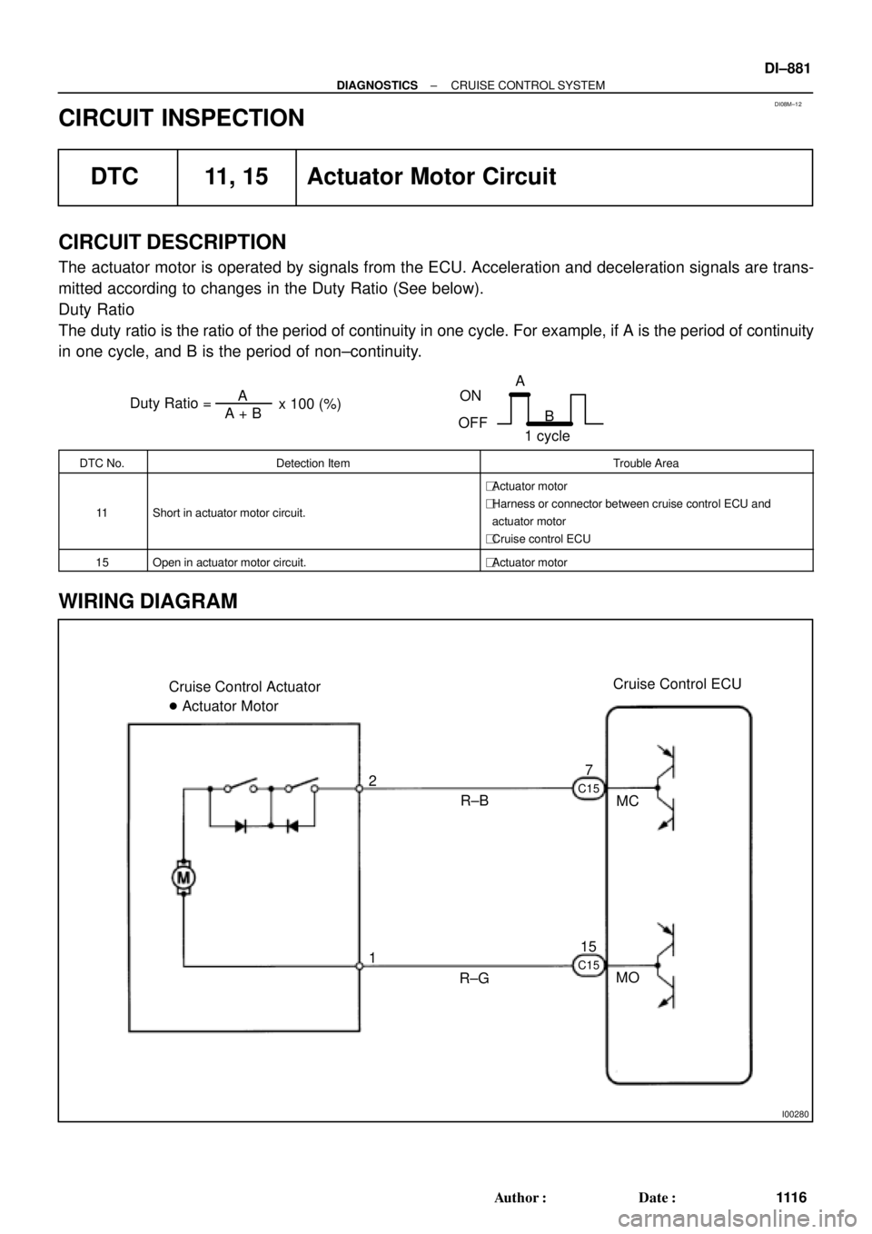
DI08M±12
Duty Ratio =A + BA
x 100 (%)
ON
OFFA
B
1 cycle
I00280
Cruise Control ECU
MC 7
MO R±B Cruise Control Actuator
� Actuator Motor
R±G 1 2
15
C15 C15
± DIAGNOSTICSCRUISE CONTROL SYSTEM
DI±881
111 6 Author�: Date�:
CIRCUIT INSPECTION
DTC 11, 15 Actuator Motor Circuit
CIRCUIT DESCRIPTION
The actuator motor is operated by signals from the ECU. Acceleration and deceleration signals are trans-
mitted according to changes in the Duty Ratio (See below).
Duty Ratio
The duty ratio is the ratio of the period of continuity in one cycle. For example, if A is the period of continuity
in one cycle, and B is the period of non±continuity.
DTC No.Detection ItemTrouble Area
11Short in actuator motor circuit.
�Actuator motor
�Harness or connector between cruise control ECU and
actuator motor
�Cruise control ECU
15Open in actuator motor circuit.�Actuator motor
WIRING DIAGRAM
Page 2095 of 4592

I00281
Cruise Control ECU
C15
G±B
2 1 34W±B
3
STOP Fuse8 Stop Light Switch
4
R±Y
Stop Lights Cruise Control Actuator
� Actuator Magnetic Clutch
J7
J7AAJ/C
W±B
1J
1J
W±B
A
J/C
IG 8
7
J11Instrument
Panel J/BL
± DIAGNOSTICSCRUISE CONTROL SYSTEM
DI±883
111 8 Author�: Date�:
DTC 12 Actuator Magnetic Clutch Circuit
CIRCUIT DESCRIPTION
This circuit turns on the magnetic clutch inside the actuator during cruise control operation according to the
signal from the ECU. If a malfunction occurs in the actuator or speed sensor, etc. during cruise control opera-
tion, the rotor shaft between the motor and control plate is released.
When the brake pedal is depressed, the stop light switch turns on, supplying electrical power to the stop light.
Power supply to the magnetic clutch is mechanically cut and the magnetic clutch is turned OFF.
When driving downhill, if the vehicle speed exceeds the set speed by 15 km/h (9 mph), the ECU turns the
safety magnet clutch OFF. If the vehicle speed later drops to within 10 km/h (6 mph), cruise control at the
set speed is resumed.
DTC No.Detection ItemTrouble Area
12Short in actuator magnetic clutch circuit.
Open (0.8 sec.) in actuator magnetic clutch circuit.
�STOP Fuse
�Stop light switch
�Actuator magnetic clutch
�Harness or connector between cruise control ECU and
actuator magnetic clutch, actuator magnetic clutch and body
ground
�Cruise control ECU
WIRING DIAGRAM
DI08N±12
Page 2098 of 4592
I00055
4
3(+)
(±)
DI±886
± DIAGNOSTICSCRUISE CONTROL SYSTEM
1121 Author�: Date�:
DTC 14 Actuator Mechanical Malfunction
CIRCUIT DESCRIPTION
The circuit detects the rotation position of the actuator control plate and sends a signal to the ECU.
DTC No.Detection ItemTrouble Area
14Cruise control actuator mechanical malfunction.
�Actuator lock: (motor, arm)
�Actuator motor
�Cruise control ECU
WIRING DIAGRAM
See page DI±881.
INSPECTION PROCEDURE
1 Check cruise control actuator arm locking operation
PREPARATION:
(a) Turn ignition switch OFF.
(b) Disconnect the actuator connector.
CHECK:
Connect the positive (+) lead from the battery to the terminal 3
of actuator and the negative (±) lead to terminal 4.
NOTICE:
Do not connect the high tension cables to the wrong bat-
tery terminal. The cruise control actuator will be damaged.
Move the control plate by hand.
OK:
Control plate doesn't move.
NG Replace cruise control actuator.
OK
DI08O±12