Page 1994 of 4592
H02751
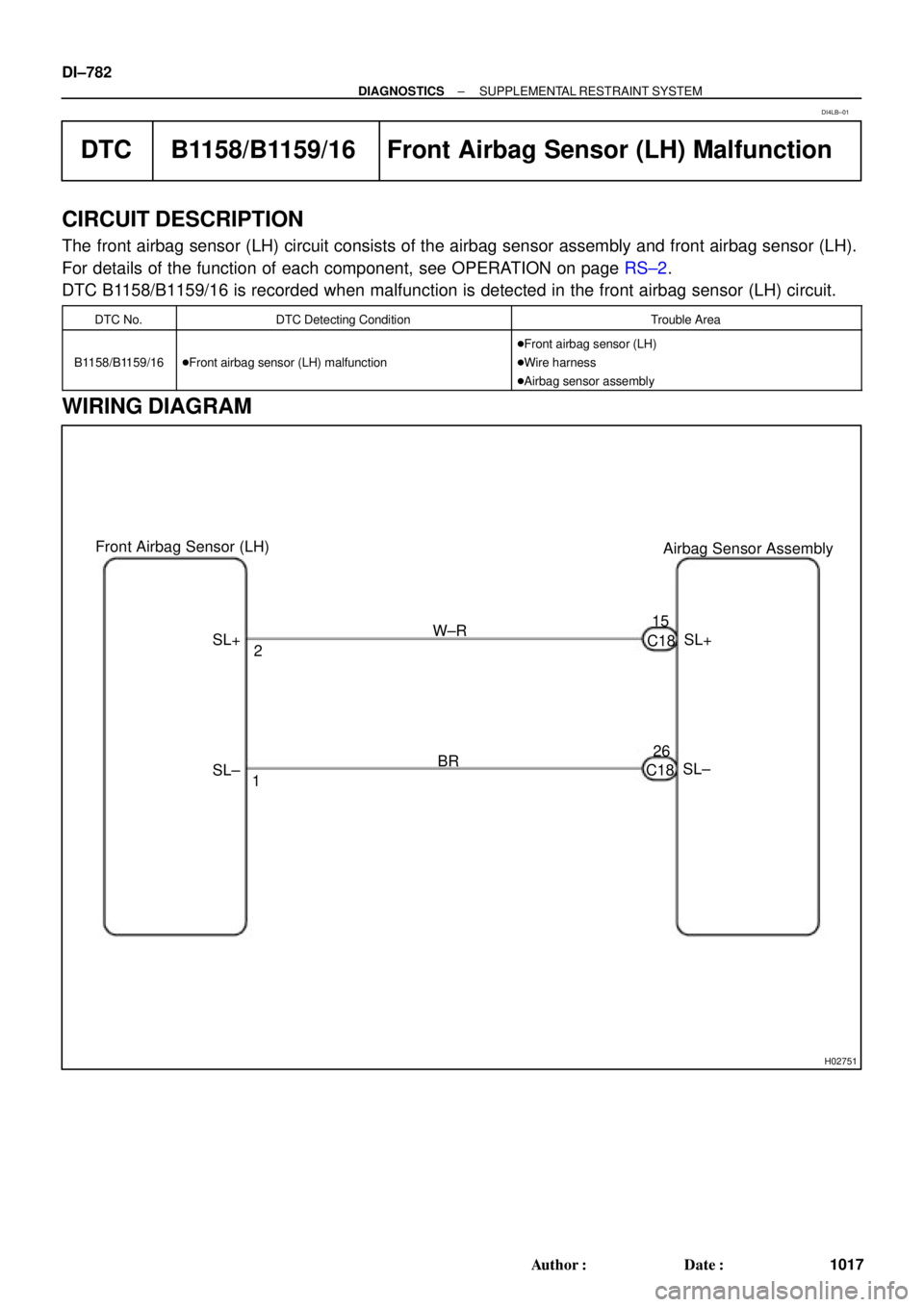
Airbag Sensor Assembly Front Airbag Sensor (LH)
SL+
SL± C1815
26 2
1 SL+W±R
BR
SL± C18 DI±782
± DIAGNOSTICSSUPPLEMENTAL RESTRAINT SYSTEM
1017 Author�: Date�:
DTC B1158/B1159/16 Front Airbag Sensor (LH) Malfunction
CIRCUIT DESCRIPTION
The front airbag sensor (LH) circuit consists of the airbag sensor assembly and front airbag sensor (LH).
For details of the function of each component, see OPERATION on page RS±2.
DTC B1158/B1159/16 is recorded when malfunction is detected in the front airbag sensor (LH) circuit.
DTC No.DTC Detecting ConditionTrouble Area
B1158/B1159/16�Front airbag sensor (LH) malfunction
�Front airbag sensor (LH)
�Wire harness
�Airbag sensor assembly
WIRING DIAGRAM
DI4LB±01
Page 1999 of 4592

H02288
15A CIG
L±R 2Airbag Sensor
Assembly 2
3 4
6 7
6
3B±R
65A IGN
C18 1K
IG 1K
1N1N
C18 Instrument Panel J/B
30A AM2
W±R W±R1
4 40A AM1
2L
1K2A
1B
1K1B
55 W2
1
2 Instrument Panel J/B
AF9 F4F6 FL MAIN
B±G
100A
ALT
Instrument Panel J/B Junction
Connector
W±B7
1J 1NW±BC18
1 Battery
1 1
2
5
B±O
GR
ACCIG2 Fusible Link Block
27
E1 Ignition Switch1 B±RB
± DIAGNOSTICSSUPPLEMENTAL RESTRAINT SYSTEM
DI±787
1022 Author�: Date�:
DTC Normal Source Voltage Drop
CIRCUIT DESCRIPTION
The SRS is equipped with a voltage±increase circuit (DC±DC converter) in the airbag sensor assembly in
case the source voltage drops.
When the battery voltage drops, the voltage±increase circuit (DC±DC converter) functions to increase the
voltage of the SRS to normal voltage.
The diagnosis system malfunction display for this circuit is different from other circuits that is when the SRS
warning light remains lit up and the DTC is a normal code, source voltage drop is indicated.
Malfunction in this circuit is not recorded in the airbag sensor assembly, and the source voltage returns to
normal, the SRS warning light automatically goes off.
DTC No.Diagnosis
(Normal)Source voltage drop
WIRING DIAGRAM
DI1BN±08
Page 2002 of 4592

H02289
2 Airbag Sensor
Assembly
237
B±Y
12 IG2
C18LG
AB10A
ECU±B
Short Pin
W±R
1W Engine Room J/B No.2
11 B
II3 A
A 3
LG
5DLC1 1 Battery
4 J3 Junction
Connector
1G2J 2A B±G
F4 F6 FL MAINFusible Link Block
1
1
TCP±B7Instrument Panel J/B
C18
B A LAW±R
LG
13
TC B±Y (*1)
LG (*2)
LG±R (*3)
P±B (*4)
II3 LG±R11
B B
TC LG±R J3 Junction
Connector
19
DLC2 SRS Warning Light
*1: TMMK Made, 1MZ±FE
*2: Except *1
*3: TMC Made
*4: TMMK Made DI±790
± DIAGNOSTICSSUPPLEMENTAL RESTRAINT SYSTEM
1025 Author�: Date�:
SRS Warning Light Circuit Malfunction (Always lights up, when
ignition switch is in LOCK position.)
CIRCUIT DESCRIPTION
The SRS warning light is located on the combination meter.
When the SRS is normal, the SRS warning light lights up for approx. 6 seconds after the ignition switch is
turned from the LOCK position to ACC or ON position, and then turns off automatically.
If there is a malfunction in the SRS, the SRS warning light lights up to inform the driver of the abnormality.
When terminals Tc and E1 of the DLC1 are connected, the DTC is displayed by blinking the SRS warning
light.
WIRING DIAGRAM
DI1BO±08
Page 2004 of 4592

CIRCUIT DES")
N14677
Fuse
DI±792
± DIAGNOSTICSSUPPLEMENTAL RESTRAINT SYSTEM
1027 Author�: Date�:
SRS Warning Light Circuit Malfunction (Does not light up, when
ignition switch is turned to ACC or ON.)
CIRCUIT DESCRIPTION
The SRS warning light is located on the combination meter.
When the SRS is normal, the SRS warning light lights up for approx. 6 seconds after the ignition switch is
turned from LOCK position to ACC or ON position, and then turns off automatically.
If there is a malfunction in the SRS, the SRS warning light lights up to inform the driver of the abnormality.
When terminals Tc and E1 of the DLC1 are connected, the DTC is displayed by blinking the SRS warning
light.
WIRING DIAGRAM
See page DI±790.
INSPECTION PROCEDURE
1 Check ECU±B Fuse.
PREPARATION:
Remove ECU±B fuse.
CHECK:
Check continuity of ECU±B fuse.
OK:
Continuity
HINT:
�Fuse may be burnt out even if it appears to be OK during
visual inspection.
�If fuse is OK, install it.
NG Go to step 5.
OK
2 Prepare for inspection. (See step 1 on page DI±787)
DI1BP±08
Page 2008 of 4592
H08301
LG±R P±B
B
BJ3 Junction
ConnectorAirbag Sensor
Assembly
A2119
Tc
11
LG±R 11
Tc
E1DLC1
3 BR
A
J22 (1MZ±FE)
J23 (5S±FE)
Junction Connector
BR (*4)
ECEC BR A
Junction
Connector
6
J7B
J8 C
BR 3
E1Tc DLC2 LG±R (*1)
P±B (*2)
4
B II3
II3
BR
J22
Junction Connector
A A BR BR (*3)J26
Junction
ConnectorB
B
BR (*3)
*1: TMC Made
*2: TMMK Made
*3: California, 1MZ±FE
*4: Except California DI±796
± DIAGNOSTICSSUPPLEMENTAL RESTRAINT SYSTEM
1031 Author�: Date�:
Tc Terminal Circuit
CIRCUIT DESCRIPTION
By connecting terminals Tc and E1 of the DLC1 the airbag sensor assembly is set in the DTC output mode.
The DTCs are displayed by blinking the SRS warning light.
WIRING DIAGRAM
DI1BQ±08
Page 2022 of 4592
DI05R±03
I00225
Wireless Door Lock ECU
SHORT PIN
2A2J
DOME Engine Room J/B No.2
FL BLOCK
BatteryRR± J16J17
W±BJ5
A
GND B±G1
B12
FL MAIN
A
IF R
RED 1
1
1 1
8
12 R±YDIODE(DOME) 1W
1G
R8 Instrument
panel J/B F6
F4
J/C
W±B DI±810
± DIAGNOSTICSWIRELESS DOOR LOCK CONTROL SYSTEM
1045 Author�: Date�:
CIRCUIT INSPECTION
ECU Power Source Circuit
CIRCUIT DESCRIPTION
Battery positive voltage is always applied to the terminal +B of the wireless door lock ECU.
WIRING DIAGRAM
Page 2023 of 4592
N14677
AB0117
N14690
I00242
LOCK
E(±)
+B(+)
± DIAGNOSTICSWIRELESS DOOR LOCK CONTROL SYSTEM
DI±811
1046 Author�: Date�:
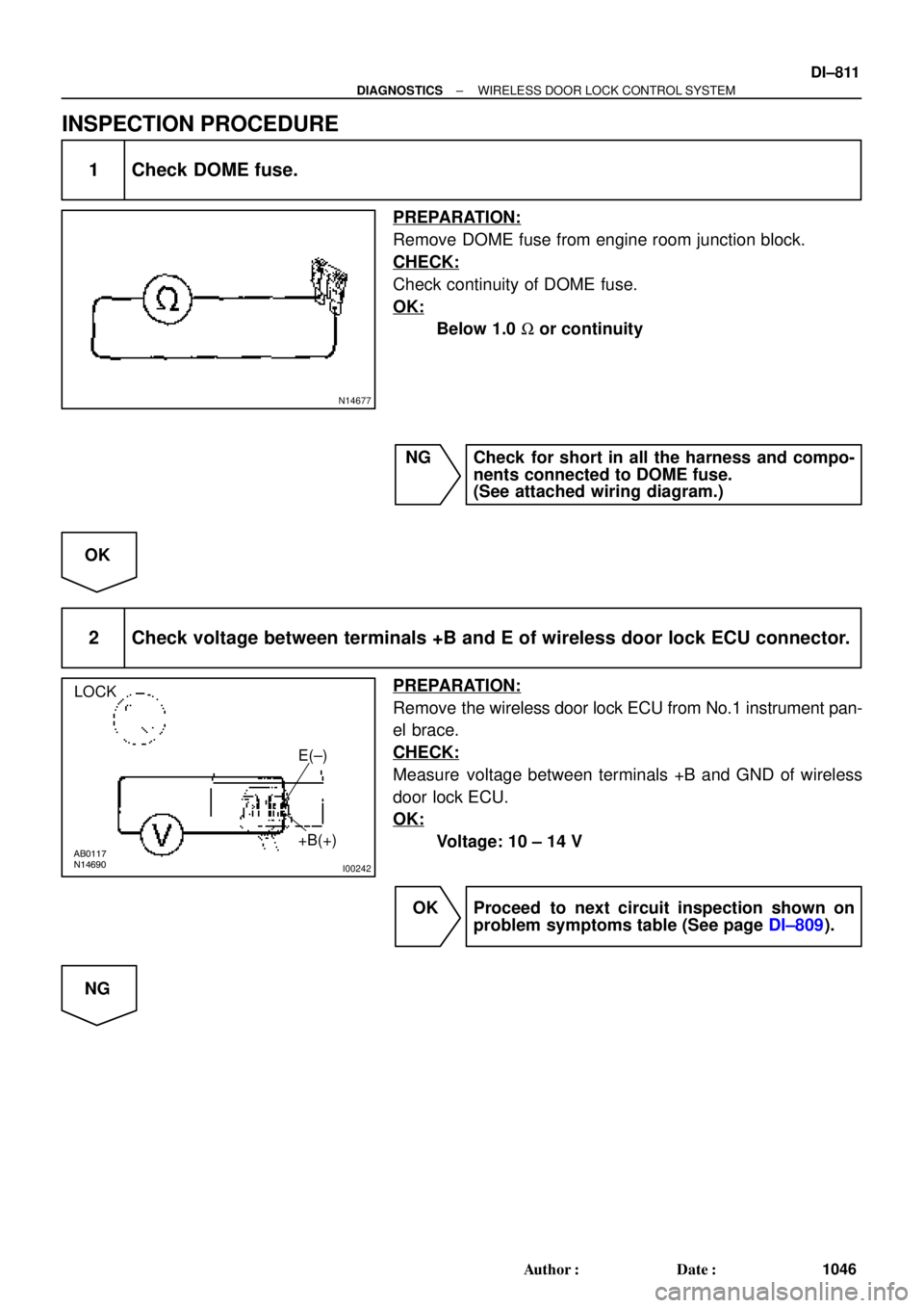
INSPECTION PROCEDURE
1 Check DOME fuse.
PREPARATION:
Remove DOME fuse from engine room junction block.
CHECK:
Check continuity of DOME fuse.
OK:
Below 1.0 W or continuity
NG Check for short in all the harness and compo-
nents connected to DOME fuse.
(See attached wiring diagram.)
OK
2 Check voltage between terminals +B and E of wireless door lock ECU connector.
PREPARATION:
Remove the wireless door lock ECU from No.1 instrument pan-
el brace.
CHECK:
Measure voltage between terminals +B and GND of wireless
door lock ECU.
OK:
Voltage: 10 ± 14 V
OK Proceed to next circuit inspection shown on
problem symptoms table (See page DI±809).
NG
Page 2025 of 4592

I08425
Theft Deterrent ECU
LSWD14
T4
LSWP
LSWR15
T4
16
T4Wireless Door
Lock ECU
W±B
*2
Door Unlock Detection
Switch Rear RH IE
Instrument Panel J/B J6
J/C
F
1111
L±RF
F
YL±R
LSWD
LSWP
LSWR W6
12
W6
13
W6 L±R L±R
IE1
Door Unlock Detection
Switch Rear LHDoor Unlock Detection
Switch Front RH Door Unlock
Detection Switch
Front LH
W±B*1W±B*1J38
20
W±B
J/C A
A
1
3 243 2
3 23 2 IE1
W±B3C
L±YE
J101V7
1GJ37 J/C
C
CY
Y Y11
IM1
1*1
4*2
W±B*1J39
J/CW±B*1
A
A
IM1 20
W±B
BN
IJ
IK L±Y J/C
D
J9
D J9 EJ10
L±Y L±Y L±Y
L±YL±Y L±Y
4
BO12
IF23
IN24
BP14
1
W±BW±B6
BP1
4 1
W±B
W±B6
BO1J40
J/CBL
4*1
1*2
*1: TMC Made
*2: TMMK Made W±BW±B
*2
± DIAGNOSTICSWIRELESS DOOR LOCK CONTROL SYSTEM
DI±813
1048 Author�: Date�:
Door Unlock Detection Switch Circuit
CIRCUIT DESCRIPTION
The door unlock detection switch is built into the door lock motor assembly. The switch is OFF when the
door lock knob is in Lock position, and is ON When the Knob is in Unlock position.
Furthermore, the door unlock detection switch circuit has terminal +B connected inside the theft deterrent
ECU, when the door unlock detection switch is OFF, battery positive voltage is applied to the terminal of the
door unlock detection switch circuit of the wireless door lock ECU.
WIRING DIAGRAM
DI05S±03

J23 (5S±FE)
Junction Connector
BR (*4)
ECEC BR A
Junction
Connector
6
J7B
J8 C
BR")
 1W
1G
R8 Instrument")