Page 1894 of 4592
Airbag
Sensor
Assembly
SFR+ SFR±
DI±682
± DIAGNOSTICSSUPPLEMENTAL RESTRAINT SYSTEM
917 Author�: Date�:
DTC B0111/44 Open in Side Squib (RH) Circuit
(TMMK Made)
CIRCUIT")
H02272W03859H02315
Squib (RH)Airbag
Sensor
Assembly
SFR+ SFR±
DI±682
± DIAGNOSTICSSUPPLEMENTAL RESTRAINT SYSTEM
917 Author�: Date�:
DTC B0111/44 Open in Side Squib (RH) Circuit
(TMMK Made)
CIRCUIT DESCRIPTION
The side squib circuit consists of the airbag sensor assembly and side airbag assembly (RH).
It causes the SRS to deploy when the SRS deployment conditions are satisfied.
For details of the function of each component, see OPERATION on page RS±2.
DTC B0111/44 is recorded when an open is detected in the side squib (RH) circuit.
DTC No.DTC Detecting ConditionTrouble Area
B0111/44
�Open circuit in SFR+ wire harness or SFR± wire harness
of squib
�Side squib (RH) malfunction
�Airbag sensor assembly malfunction�Side airbag assembly (RH)
�Airbag sensor assembly
�Wire harness
�Sub wire harness
WIRING DIAGRAM
See page DI±674.
INSPECTION PROCEDURE
1 Prepare for inspection. (See step 1 on page DI±787)
2 Check side squib (RH) circuit.
CHECK:
For the connector (on the side airbag assembly side) between
the side airbag assembly (RH) and the airbag sensor assembly,
measure the resistance between SFR+ and SFR±.
OK:
Resistance: Below 1 W
NG Go to step 5.
OK
DI1L0±02
Page 1898 of 4592

(+)SFR+
(±)
DI±686
± DIAGNOSTICSSUPPLEMENTAL RESTRAINT SYSTEM
921 Author�: Date�:
DTC B0112/41 Short in Side Squib (RH) Circuit
(to Ground) (T")
H01019H02118H02126
Airbag
Sensor
Assembly Squib (RH)
(+)SFR+
(±)
DI±686
± DIAGNOSTICSSUPPLEMENTAL RESTRAINT SYSTEM
921 Author�: Date�:
DTC B0112/41 Short in Side Squib (RH) Circuit
(to Ground) (TMC Made)
CIRCUIT DESCRIPTION
The side squib circuit consists of the airbag sensor assembly and side airbag assembly (RH).
It causes the SRS to deploy when the SRS deployment conditions are satisfied.
For details of the function of each component, see OPERATION on page RS±2.
DTC B0112/41 is recorded when ground short is detected in the side squib (RH) circuit.
DTC No.DTC Detecting ConditionTrouble Area
B0112/41
�Short circuit in side squib (RH) wire harness (to ground)
�Side squib (RH) malfunction
�Airbag sensor assembly malfunction�Side airbag assembly (RH)
�Airbag sensor assembly
�Wire harness
WIRING DIAGRAM
See page DI±670.
INSPECTION PROCEDURE
1 Prepare for inspection. (See step 1 on page DI±787)
2 Check side squib (RH) circuit.
CHECK:
For the connector (on the side airbag assembly side) between
the side airbag assembly (RH) and the airbag sensor assembly,
measure the resistance between SFR+ and body ground.
OK:
Resistance: 1 MW or Higher
NG Repair or replace harness or connector be-
tween side airbag assembly (RH) and airbag
sensor assembly.
OK
DI1BB±03
Page 1901 of 4592

(+)SFR+
(±)
± DIAGNOSTICSSUPPLEMENTAL RESTRAINT SYSTEM
DI±689
924 Author�: Date�:
DTC B0112/41 Short in Side Squib (RH) Circuit
(to Ground) (T")
H02118H02272H03251
Airbag
Sensor
Assembly Squib (RH)
(+)SFR+
(±)
± DIAGNOSTICSSUPPLEMENTAL RESTRAINT SYSTEM
DI±689
924 Author�: Date�:
DTC B0112/41 Short in Side Squib (RH) Circuit
(to Ground) (TMMK Made)
CIRCUIT DESCRIPTION
The side squib circuit consists of the airbag sensor assembly and side airbag assembly (RH).
It causes the SRS to deploy when the SRS deployment conditions are satisfied.
For details of the function of each component, see OPERATION on page RS±2.
DTC B0112/41 is recorded when ground short is detected in the side squib (RH) circuit.
DTC No.DTC Detecting ConditionTrouble Area
B0112/41
�Short circuit in side squib (RH) wire harness (to ground)
�Side squib (RH) malfunction
�Airbag sensor assembly malfunction�Side airbag assembly (RH)
�Airbag sensor assembly
�Wire harness
�Sub wire harness
WIRING DIAGRAM
See page DI±674.
INSPECTION PROCEDURE
1 Prepare for inspection. (See step 1 on page DI±787)
2 Check side squib (RH) circuit.
CHECK:
For the connector (on the side airbag assembly side) between
the side airbag assembly (RH) and the airbag sensor assembly,
measure the resistance between SFR+ and body ground.
OK:
Resistance: 1 MW or Higher
NG Go to step 5.
OK
DI4L4±01
Page 1905 of 4592
Airbag
Sensor
Assembly
(±)
(+)SFR+
ON
± DIAGNOSTICSSUPPLEMENTAL RESTRAINT SYSTEM
DI±693
928 Author�: Date�:
DTC B0113/42 Short in Side Squib (RH) Circuit (to B+")
H01019H02119
AB0119
H08263
Squib (RH)Airbag
Sensor
Assembly
(±)
(+)SFR+
ON
± DIAGNOSTICSSUPPLEMENTAL RESTRAINT SYSTEM
DI±693
928 Author�: Date�:
DTC B0113/42 Short in Side Squib (RH) Circuit (to B+)
(TMC Made)
CIRCUIT DESCRIPTION
The side squib circuit consists of the airbag sensor assembly and side airbag assembly (RH).
It causes the SRS to deploy when the SRS deployment conditions are satisfied.
For details of the function of each component, see OPERATION on page RS±2.
DTC B0113/42 is recorded when a B+ short is detected in the side squib (RH) circuit.
DTC No.DTC Detecting ConditionTrouble Area
B0113/42
�Short circuit in side squib (RH) wire harness (to B+)
�Side squib (RH) malfunction
�Airbag sensor assembly malfunction�Side airbag assembly (RH)
�Airbag sensor assembly
�Wire harness
WIRING DIAGRAM
See page DI±670.
INSPECTION PROCEDURE
1 Prepare for inspection. (See step 1 on page DI±626)
2 Check side squib (RH) circuit.
CHECK:
(a) Turn ignition switch to ON.
(b) For the connector (on the airbag sensor assembly side)
between the side airbag assembly (RH) and the airbag
sensor assembly, measure the voltage between SFR+
and body ground.
OK:
Voltage: 0 V
NG Repair or replace harness or connector be-
tween side airbag assembly (RH) and airbag
sensor assembly.
OK
DI1BC±03
Page 1908 of 4592
Airbag
Sensor
Assembly
(±) (+)SFR+
ON
DI±696
± DIAGNOSTICSSUPPLEMENTAL RESTRAINT SYSTEM
931 Author�: Date�:
DTC B0113/42 Short in Side Squib (RH) Circuit (to B+)")
H02119H02272AB0119
H08264
Squib (RH)Airbag
Sensor
Assembly
(±) (+)SFR+
ON
DI±696
± DIAGNOSTICSSUPPLEMENTAL RESTRAINT SYSTEM
931 Author�: Date�:
DTC B0113/42 Short in Side Squib (RH) Circuit (to B+)
(TMMK Made)
CIRCUIT DESCRIPTION
The side squib circuit consists of the airbag sensor assembly and side airbag assembly (RH).
It causes the SRS to deploy when the SRS deployment conditions are satisfied.
For details of the function of each component, see OPERATION on page RS±2.
DTC B0113/42 is recorded when a B+ short is detected in the side squib (RH) circuit.
DTC No.DTC Detecting ConditionTrouble Area
B0113/42
�Short circuit in side squib (RH) wire harness (to B+)
�Side squib (RH) malfunction
�Airbag sensor assembly malfunction�Side airbag assembly (RH)
�Airbag sensor assembly
�Wire harness
�Sub wire harness
WIRING DIAGRAM
See page DI±674.
INSPECTION PROCEDURE
1 Prepare for inspection. (See step 1 on page DI±787)
2 Check side squib (RH) circuit.
CHECK:
(a) Turn ignition switch to ON.
(b) For the connector (on the airbag sensor assembly side)
between the side airbag assembly (RH) and the airbag
sensor assembly, measure the voltage between the
SFR+ and body ground.
OK:
Voltage: 0 V
NG Go to step 5.
OK
DI4L5±01
Page 1912 of 4592
H01454
Side Squib (LH)Airbag Sensor Assembly
SFL+
SFL± Y±R
Y±G 1
26 5
C17
C17 DI±700
± DIAGNOSTICSSUPPLEMENTAL RESTRAINT SYSTEM
935 Author�: Date�:
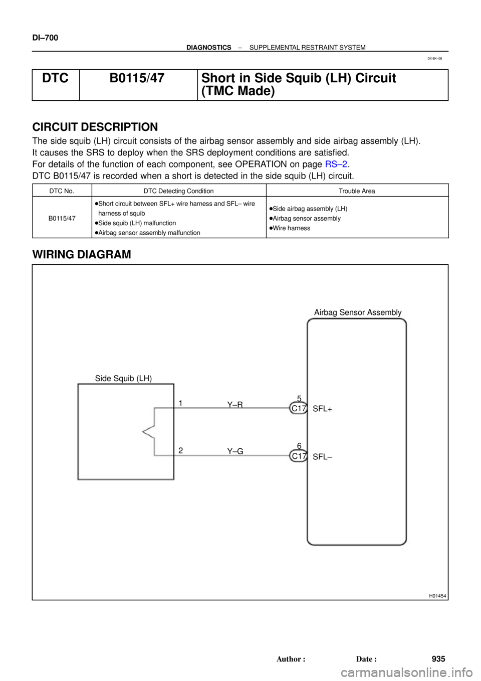
DTC B0115/47 Short in Side Squib (LH) Circuit
(TMC Made)
CIRCUIT DESCRIPTION
The side squib (LH) circuit consists of the airbag sensor assembly and side airbag assembly (LH).
It causes the SRS to deploy when the SRS deployment conditions are satisfied.
For details of the function of each component, see OPERATION on page RS±2.
DTC B0115/47 is recorded when a short is detected in the side squib (LH) circuit.
DTC No.DTC Detecting ConditionTrouble Area
B0115/47
�Short circuit between SFL+ wire harness and SFL± wire
harness of squib
�Side squib (LH) malfunction
�Airbag sensor assembly malfunction�Side airbag assembly (LH)
�Airbag sensor assembly
�Wire harness
WIRING DIAGRAM
DI16K±08
Page 1916 of 4592
H04507
Side Squib (LH)Airbag Sensor Assembly
SFL+
SFL± BV1
Y±G 1
26 5
C17
C17 Y±G Y±RY±R
BV1 DI±704
± DIAGNOSTICSSUPPLEMENTAL RESTRAINT SYSTEM
939 Author�: Date�:
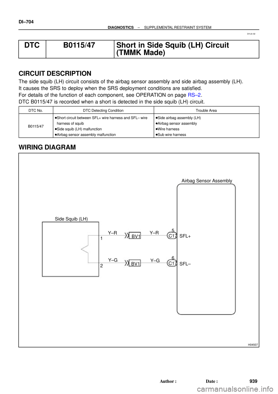
DTC B0115/47 Short in Side Squib (LH) Circuit
(TMMK Made)
CIRCUIT DESCRIPTION
The side squib (LH) circuit consists of the airbag sensor assembly and side airbag assembly (LH).
It causes the SRS to deploy when the SRS deployment conditions are satisfied.
For details of the function of each component, see OPERATION on page RS±2.
DTC B0115/47 is recorded when a short is detected in the side squib (LH) circuit.
DTC No.DTC Detecting ConditionTrouble Area
B0115/47
�Short circuit between SFL+ wire harness and SFL± wire
harness of squib
�Side squib (LH) malfunction
�Airbag sensor assembly malfunction�Side airbag assembly (LH)
�Airbag sensor assembly
�Wire harness
�Sub wire harness
WIRING DIAGRAM
DI1L6±02
Page 1921 of 4592
Airbag
Sensor
Assembly
(±) (+)
SFL±SFL+
± DIAGNOSTICSSUPPLEMENTAL RESTRAINT SYSTEM
DI±709
944 Author�: Date�:
DTC B0116/48 Open in Side Squib (LH) Circuit
(TMC Made)
C")
H01019W03859H01191
Squib (LH)Airbag
Sensor
Assembly
(±) (+)
SFL±SFL+
± DIAGNOSTICSSUPPLEMENTAL RESTRAINT SYSTEM
DI±709
944 Author�: Date�:
DTC B0116/48 Open in Side Squib (LH) Circuit
(TMC Made)
CIRCUIT DESCRIPTION
The side squib circuit consists of the airbag sensor assembly and side airbag assembly (LH).
It causes the SRS to deploy when the SRS deployment conditions are satisfied.
For details of the function of each component, see OPERATION on page RS±2.
DTC B0116/48 is recorded when an open is detected in the side squib (LH) circuit.
DTC No.DTC Detecting ConditionTrouble Area
B0116/48
�Open circuit in SFL+ wire harness or SFL± wire harness
of squib
�Side squib (LH) malfunction
�Airbag sensor assembly malfunction�Side airbag assembly (LH)
�Airbag sensor assembly
�Wire harness
WIRING DIAGRAM
See page DI±700.
INSPECTION PROCEDURE
1 Prepare for inspection. (See step 1 on page DI±787)
2 Check side squib (LH) circuit.
CHECK:
For the connector (on the side airbag assembly side) between
the side airbag assembly (LH) and the airbag sensor assembly,
measure the resistance between SFL+ and SFL±.
OK:
Resistance: Below 1 W
NG Repair or replace harness or connector be-
tween side airbag assembly (LH) and airbag
sensor assembly.
OK
DI1BD±03