Page 2027 of 4592

I08426
Wireless Door Lock ECU
Theft Deterrent ECU Integration Relay
UL3 R±G9
T4 I18
UL2 10
T4 UL27
W6R±G R±GI18
B
J6
J/C
3
IE1
74*1
19*25*1
20*2
B
B
B
R±G
R±G
Instrument Panel J/B
1G3
1V
IE 20J37 J/C
RH
J38 W±B
IE1
J/C AA W±B
*3W±B*3
W±B*4
32
UNLOCK LOCK
Door Key
Lock and
Unlock
SwitchLL
L AA
A
3IM1
32
1
UNLOCK LOCK
L
J39
J/C AA W±B
*3W±B*3
W±B*4
20 IM1W±B
1LH
IJ *1: w/o Theft Deterrent System
*2: w/ Theft Deterrent System
*3: TMC Made
*4: TMMK Made
± DIAGNOSTICSWIRELESS DOOR LOCK CONTROL SYSTEM
DI±815
1050 Author�: Date�:
Door Key Lock and Unlock Switch Circuit (Unlock Side)
CIRCUIT DESCRIPTION
The Key±operated switch is built into the door key cylinder. When the key is turned to the lock side, the lock
terminal of the switch is grounded, and when the key is turned to the unlock side the unlock terminal is
grounded.
Furthermore, the door key lock and unlock switch circuit has terminal +B connected inside the theft deterrent
ECU, when neither the lock nor unlock terminal of the key lock and unlock switch are grounded, battery posi-
tive voltage is applied to the door key lock and unlock switch circuit of the wireless door lock ECU.
( Tr inside the ECU coming ON causes the wireless door lock ECU to output a signal to unlock all the doors.)
WIRING DIAGRAM
DI05T±03
Page 2029 of 4592
I08427
Wireless Door Lock ECUIntegration Relay
L2 8
T4 I18
L15
W6
BJ37
J/C
4
IE1
7B
B B
1G3
1V
IE 20RH
J38 W±B
IE1
J/C AA W±B
*3W±B*3
W±B*4
32
UNLOCK LOCK
Door Key
Lock and
Unlock
Switch4
IM1
32
1
UNLOCK LOCK
L±W
J39
J/C A
A W±B
*3W±B*3
W±B*4
20 IM1W±B
1LH
IJ*1: w/o Theft Deterrent System
*2: w/ Theft Deterrent System
*3: TMC Made
*4: TMMK Made
Theft Deterrent ECU
W±B Instrument Panel J/BL±W
L±W
L±W L±W3
*1
18*2
B L±W
L±W
± DIAGNOSTICSWIRELESS DOOR LOCK CONTROL SYSTEM
DI±817
1052 Author�: Date�:
Door Key Lock and Unlock Switch Circuit (Lock Side)
CIRCUIT DESCRIPTION
Refer to page DI±815.
Tr inside the wireless door lock ECU coming ON causes the theft deterrent ECU to output a signal to lock
all the doors.
WIRING DIAGRAM
DI05U±03
Page 2031 of 4592
I00224
Wireless Door Lock ECU
Key Unlock
Warning
SwitchKSW L±B
W±B
1M1J7 5 5
1
2
3 7
IG10
1D
J/C L±B
W±B1M
Integration Relay
Instrument Panel J/BW6 J10 Instrument Panel J/B
L±B B
J9B
J11
A
± DIAGNOSTICSWIRELESS DOOR LOCK CONTROL SYSTEM
DI±819
1054 Author�: Date�:
Key Unlock Warning Switch Circuit
CIRCUIT DESCRIPTION
When the key is inserted in the ignition key cylinder, the key unlock warning switch comes ON, and when
the key is not inserted the switch is OFF.
When the key unlock warning switch is ON, the ECU operates the key confinement prevention function.
WIRING DIAGRAM
DI05V±03
Page 2033 of 4592
I00223
Wireless Door
Lock ECU Theft Deterrent
ECU
Integration Relay
Door Cour-
tesy Switch R±W
R±G DSWD
CTY
DSWPR±WIN2 1G
1S J10 J9
J33 J34
ED A 4
4
6
Rear RH
Rear LHFront RH
Front LH8 1S1G R±G R±G
R±GR±W
R±G R±W R±W
4
CTY
5
6 1C
14
1
2 712
11 11 R±W J33J33
J34D
DE
R±G
J33
J33
J34 DE
ER±W
T4W6 T4
T4
IN2R±G Instrument Panel J/B
1
± DIAGNOSTICSWIRELESS DOOR LOCK CONTROL SYSTEM
DI±821
1056 Author�: Date�:
Door Courtesy Switch Circuit
CIRCUIT DESCRIPTION
The door courtesy switch comes ON when the door is opened and goes OFF when door is closed. Further-
more. the door courtesy switch circuit has terminal +B connected inside the theft deterrent ECU . Battery
positive voltage is applied to terminal DSWD of the theft deterrent ECU when all doors are closed, i.e., when
the door courtesy switches of all doors are OFF.
WIRING DIAGRAM
DI05W±03
Page 2035 of 4592
I00301
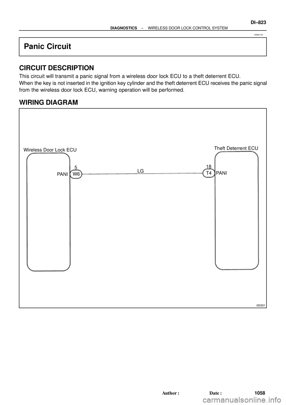
Wireless Door Lock ECUTheft Deterrent ECU
518
LG
PANI
PANIW6T4
± DIAGNOSTICSWIRELESS DOOR LOCK CONTROL SYSTEM
DI±823
1058 Author�: Date�:
Panic Circuit
CIRCUIT DESCRIPTION
This circuit will transmit a panic signal from a wireless door lock ECU to a theft deterrent ECU.
When the key is not inserted in the ignition key cylinder and the theft deterrent ECU receives the panic signal
from the wireless door lock ECU, warning operation will be performed.
WIRING DIAGRAM
DI05X±04
Page 2050 of 4592
DI06S±04
I04447
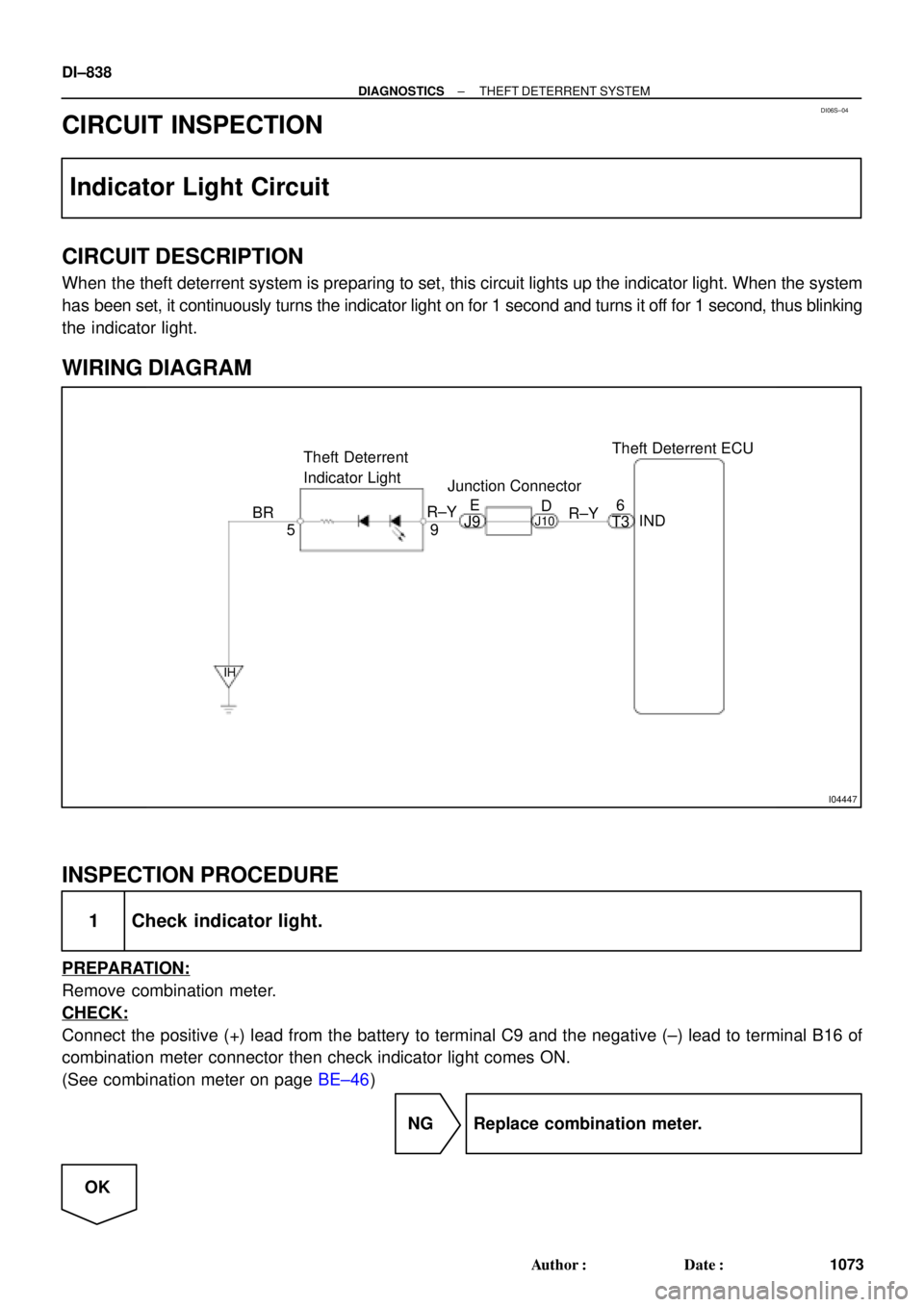
Theft Deterrent ECU
9 Theft Deterrent
Indicator Light
5IND 6
BR
IH
R±Y
T3 R±YE
D
J9J10
Junction Connector
DI±838
± DIAGNOSTICSTHEFT DETERRENT SYSTEM
1073 Author�: Date�:
CIRCUIT INSPECTION
Indicator Light Circuit
CIRCUIT DESCRIPTION
When the theft deterrent system is preparing to set, this circuit lights up the indicator light. When the system
has been set, it continuously turns the indicator light on for 1 second and turns it off for 1 second, thus blinking
the indicator light.
WIRING DIAGRAM
INSPECTION PROCEDURE
1 Check indicator light.
PREPARATION:
Remove combination meter.
CHECK:
Connect the positive (+) lead from the battery to terminal C9 and the negative (±) lead to terminal B16 of
combination meter connector then check indicator light comes ON.
(See combination meter on page BE±46)
NG Replace combination meter.
OK
Page 2052 of 4592
I00238
Theft Deterrent ECU
+B2
E
W±B L±WL±W
J/C
T4
T3
J/C
1G 1
A
AD
8
1W DOME12
R
IF
R
E
T3
+B1
DOOR
J34
C
1B 1D
B±R SHORT PIN
E/G Room J/B No.2
1 4
FL BLOCK
C
R B
F6
F4F9
FL MAIN
Battery
B±G2A1
2J
111
1
7 ALT 1
1
J17 J16
Instrument Panel J/B
Instrument Panel J/B
J5
J/C
R±Y12 DIODE (DOME)
W±B
DI±840
± DIAGNOSTICSTHEFT DETERRENT SYSTEM
1075 Author�: Date�:
ECU Power Source Circuit
CIRCUIT DESCRIPTION
This circuit provides power to operate the theft deterrent ECU.
WIRING DIAGRAM
DI06T±06
Page 2053 of 4592
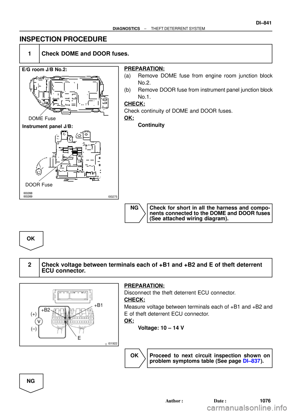
I00268
I00269
I00275
E/G room J/B No.2:
Instrument panel J/B:DOME Fuse
DOOR Fuse
I01922E+B1
+B2
(+)
(±)
± DIAGNOSTICSTHEFT DETERRENT SYSTEM
DI±841
1076 Author�: Date�:
INSPECTION PROCEDURE
1 Check DOME and DOOR fuses.
PREPARATION:
(a) Remove DOME fuse from engine room junction block
No.2.
(b) Remove DOOR fuse from instrument panel junction block
No.1.
CHECK:
Check continuity of DOME and DOOR fuses.
OK:
Continuity
NG Check for short in all the harness and compo-
nents connected to the DOME and DOOR fuses
(See attached wiring diagram).
OK
2 Check voltage between terminals each of +B1 and +B2 and E of theft deterrent
ECU connector.
PREPARATION:
Disconnect the theft deterrent ECU connector.
CHECK:
Measure voltage between terminals each of +B1 and +B2 and
E of theft deterrent ECU connector.
OK:
Voltage: 10 ± 14 V
OK Proceed to next circuit inspection shown on
problem symptoms table (See page DI±837).
NG