Page 1865 of 4592
 (+)
ON
± DIAGNOSTICSSUPPLEMENTAL RESTRAINT SYSTEM
DI±653
888 Author�: Date�:
DTC B0103/12 Short in D Squib Circuit (to B")
H01001
R14288AB0119
H04530
D SquibSpiral
Cable
Airbag
Sensor
Assembly
D+
(±) (+)
ON
± DIAGNOSTICSSUPPLEMENTAL RESTRAINT SYSTEM
DI±653
888 Author�: Date�:
DTC B0103/12 Short in D Squib Circuit (to B+)
CIRCUIT DESCRIPTION
The D squib circuit consists of the airbag sensor assembly, spiral cable and steering wheel pad.
It causes the SRS to deploy when the SRS deployment conditions are satisfied.
For details of the function of each component, see OPERATION on page RS±2.
DTC B0103/12 is recorded when a B+ short is detected in the D squib circuit.
DTC No.DTC Detecting ConditionTrouble Area
B0103/12
�Short circuit in D squib wire harness (to B+)
�D squib malfunction
�Spiral cable malfunction
�Airbag sensor assembly malfunction�Steering wheel pad (D squib)
�Spiral cable
�Airbag sensor assembly
�Wire harness
WIRING DIAGRAM
See page DI±640.
INSPECTION PROCEDURE
1 Prepare for inspection. (See step 1 on page DI±787)
2 Check D squib circuit.
CHECK:
(a) Turn ignition switch to ON.
(b) For the connector (on the spiral cable side) between the
spiral cable and the steering wheel pad, measure the volt-
age between D+ and body ground.
OK:
Voltage: 0 V
NG Go to step 5.
OK
DI4L3±01
Page 1869 of 4592
H01454
P Squib
10Airbag Sensor Assembly
2Y±R
C18
Y±G 1
11
C18P+
P±
± DIAGNOSTICSSUPPLEMENTAL RESTRAINT SYSTEM
DI±657
892 Author�: Date�:
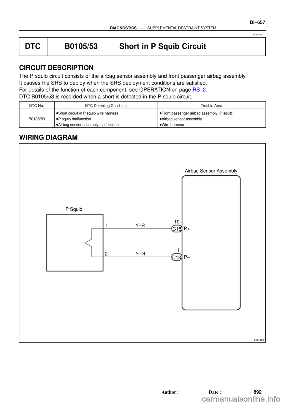
DTC B0105/53 Short in P Squib Circuit
CIRCUIT DESCRIPTION
The P squib circuit consists of the airbag sensor assembly and front passenger airbag assembly.
It causes the SRS to deploy when the SRS deployment conditions are satisfied.
For details of the function of each component, see OPERATION on page RS±2.
DTC B0105/53 is recorded when a short is detected in the P squib circuit.
DTC No.DTC Detecting ConditionTrouble Area
B0105/53
�Short circuit in P squib wire harness
�P squib malfunction
�Airbag sensor assembly malfunction�Front passenger airbag assembly (P squib)
�Airbag sensor assembly
�Wire harness
WIRING DIAGRAM
DI1B6±12
Page 1873 of 4592
(+)
± DIAGNOSTICSSUPPLEMENTAL RESTRAINT SYSTEM
DI±661
896 Author�: Date�:
DTC B0106/54 Open in P Squib Circuit
CIRCUIT DESCRIPTION
The P")
R14286H02142H02251
P Squib
Airbag
Sensor
Assembly
P +
P±
(±)(+)
± DIAGNOSTICSSUPPLEMENTAL RESTRAINT SYSTEM
DI±661
896 Author�: Date�:
DTC B0106/54 Open in P Squib Circuit
CIRCUIT DESCRIPTION
The P squib circuit consists of the airbag sensor assembly and front passenger airbag assembly.
It causes the SRS to deploy when the SRS deployment conditions are satisfied.
For details of the function of each component, see OPERATION on page RS±2.
DTC B0106/54 is recorded when an open is detected in the P squib circuit.
DTC No.DTC Detecting ConditionTrouble Area
B0106/54
�Open circuit in P+ wire harness or P± wire harness of
squib
�P squib malfunction
�Airbag sensor assembly malfunction�Front passenger airbag assembly (P squib)
�Airbag sensor assembly
�Wire harness
WIRING DIAGRAM
See page DI±657.
INSPECTION PROCEDURE
1 Prepare for inspection. (See step 1 on page DI±787)
2 Check P squib circuit.
CHECK:
For the connector (on the front passenger airbag assembly
side) between the front passenger airbag assembly and the air-
bag sensor assembly, measure the resistance between P+ and
P±.
OK:
Resistance: Below 1 W
NG Repair or replace harness or connector be-
tween front passenger airbag assembly and air-
bag sensor assembly.
OK
DI1B7±17
Page 1876 of 4592

(±)P+
DI±664
± DIAGNOSTICSSUPPLEMENTAL RESTRAINT SYSTEM
899 Author�: Date�:
DTC B0107/51 Short in P Squib Circuit (to Ground)
CIRCUIT DESCRIPTI")
H01227H02145H02254
P Squib
Airbag
Sensor
Assembly
(+)
(±)P+
DI±664
± DIAGNOSTICSSUPPLEMENTAL RESTRAINT SYSTEM
899 Author�: Date�:
DTC B0107/51 Short in P Squib Circuit (to Ground)
CIRCUIT DESCRIPTION
The P squib circuit consists of the airbag sensor assembly and front passenger airbag assembly.
It causes the SRS to deploy when the SRS deployment conditions are satisfied.
For details of the function of each component, see OPERATION on page RS±2.
DTC B0107/51 is recorded when ground short is detected in the P squib circuit.
DTC No.DTC Detecting ConditionTrouble Area
B0107/51
�Short circuit in P squib wire harness (to ground)
�P squib malfunction
�Airbag sensor assembly malfunction�Front passenger airbag assembly (P squib)
�Airbag sensor assembly
�Wire harness
WIRING DIAGRAM
See page DI±657.
INSPECTION PROCEDURE
1 Prepare for inspection. (See step 1 on page DI±787)
2 Check P squib circuit.
CHECK:
For the connector (on the front passenger airbag assembly
side) between the front passenger airbag assembly and the air-
bag sensor assembly, measure the resistance between P+ and
body ground.
OK:
Resistance: 1 MW or Higher
NG Repair or replace harness or connector be-
tween front passenger airbag assembly and air-
bag sensor assembly.
OK
DI1B8±11
Page 1879 of 4592
 (+)P+ ON
± DIAGNOSTICSSUPPLEMENTAL RESTRAINT SYSTEM
DI±667
902 Author�: Date�:
DTC B0108/52 Short in P Squib Circuit (to B+)
CIRCUIT DES")
H01022H02146
AB0119
H08262
P SquibAirbag
Sensor
Assembly
(±) (+)P+ ON
± DIAGNOSTICSSUPPLEMENTAL RESTRAINT SYSTEM
DI±667
902 Author�: Date�:
DTC B0108/52 Short in P Squib Circuit (to B+)
CIRCUIT DESCRIPTION
The P squib circuit consists of the airbag sensor assembly and front passenger airbag assembly.
It causes the SRS to deploy when the SRS deployment conditions are satisfied.
For details of the function of each component, see OPERATION on page RS±2.
DTC B0108/52 is recorded when a B+ short is detected in the P squib circuit.
DTC No.DTC Detecting ConditionTrouble Area
B0108/52
�Short circuit in P squib wire harness (to B+)
�P squib malfunction
�Airbag sensor assembly malfunction�Front passenger airbag assembly (P squib)
�Airbag sensor assembly
�Wire harness
WIRING DIAGRAM
See page DI±657.
INSPECTION PROCEDURE
1 Prepare for inspection. (See step 1 on page DI±787)
2 Check P squib circuit.
CHECK:
(a) Turn ignition switch to ON.
(b) For the connector (on the front passenger airbag assem-
bly side) between the front passenger airbag assembly
and the airbag sensor assembly, measure the voltage be-
tween the P+ and body ground.
OK:
Voltage: 0 V
NG Repair or replace harness or connector be-
tween front passenger airbag assembly and air-
bag sensor assembly.
OK
DI1B9±16
Page 1882 of 4592
H01454
Side Squib (RH)Airbag Sensor Assembly
SFR+
SFR± Y±R
Y±G 1
21 2
C19
C19 DI±670
± DIAGNOSTICSSUPPLEMENTAL RESTRAINT SYSTEM
905 Author�: Date�:
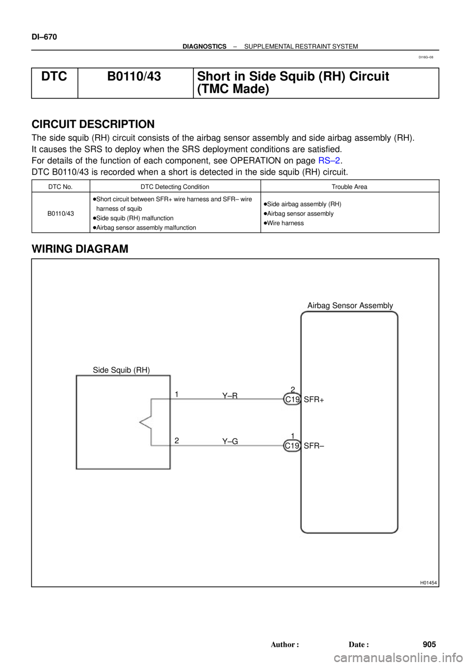
DTC B0110/43 Short in Side Squib (RH) Circuit
(TMC Made)
CIRCUIT DESCRIPTION
The side squib (RH) circuit consists of the airbag sensor assembly and side airbag assembly (RH).
It causes the SRS to deploy when the SRS deployment conditions are satisfied.
For details of the function of each component, see OPERATION on page RS±2.
DTC B0110/43 is recorded when a short is detected in the side squib (RH) circuit.
DTC No.DTC Detecting ConditionTrouble Area
B0110/43
�Short circuit between SFR+ wire harness and SFR± wire
harness of squib
�Side squib (RH) malfunction
�Airbag sensor assembly malfunction�Side airbag assembly (RH)
�Airbag sensor assembly
�Wire harness
WIRING DIAGRAM
DI16G±08
Page 1886 of 4592
H04507
Side Squib (RH)Airbag Sensor Assembly
SFR+
SFR± Y±R
Y±G 1
21 2
C19
C19 Y±R
Y±G BW1
BW11
2 DI±674
± DIAGNOSTICSSUPPLEMENTAL RESTRAINT SYSTEM
909 Author�: Date�:
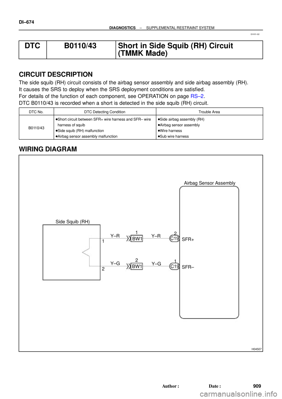
DTC B0110/43 Short in Side Squib (RH) Circuit
(TMMK Made)
CIRCUIT DESCRIPTION
The side squib (RH) circuit consists of the airbag sensor assembly and side airbag assembly (RH).
It causes the SRS to deploy when the SRS deployment conditions are satisfied.
For details of the function of each component, see OPERATION on page RS±2.
DTC B0110/43 is recorded when a short is detected in the side squib (RH) circuit.
DTC No.DTC Detecting ConditionTrouble Area
B0110/43
�Short circuit between SFR+ wire harness and SFR± wire
harness of squib
�Side squib (RH) malfunction
�Airbag sensor assembly malfunction�Side airbag assembly (RH)
�Airbag sensor assembly
�Wire harness
�Sub wire harness
WIRING DIAGRAM
DI1KY±02
Page 1891 of 4592
Airbag
Sensor
Assembly
(±) (+)
SFR+ SFR±
± DIAGNOSTICSSUPPLEMENTAL RESTRAINT SYSTEM
DI±679
914 Author�: Date�:
DTC B0111/44 Open in Side Squib (RH) Circuit
(TMC Made)")
H01019W03859H01180
Squib (RH)Airbag
Sensor
Assembly
(±) (+)
SFR+ SFR±
± DIAGNOSTICSSUPPLEMENTAL RESTRAINT SYSTEM
DI±679
914 Author�: Date�:
DTC B0111/44 Open in Side Squib (RH) Circuit
(TMC Made)
CIRCUIT DESCRIPTION
The side squib circuit consists of the airbag sensor assembly and side airbag assembly (RH).
It causes the SRS to deploy when the SRS deployment conditions are satisfied.
For details of the function of each component, see OPERATION on page RS±2.
DTC B0111/44 is recorded when an open is detected in the side squib (RH) circuit.
DTC No.DTC Detecting ConditionTrouble Area
B0111/44
�Open circuit in SFR+ wire harness or SFR± wire harness
of squib
�Side squib (RH) malfunction
�Airbag sensor assembly malfunction�Side airbag assembly (RH)
�Airbag sensor assembly
�Wire harness
WIRING DIAGRAM
See page DI±670.
INSPECTION PROCEDURE
1 Prepare for inspection. (See step 1 on page DI±787)
2 Check side squib (RH) circuit.
CHECK:
For the connector (on the side airbag assembly side) between
the side airbag assembly (RH) and the airbag sensor assembly,
measure the resistance between SFR+ and SFR±.
OK:
Resistance: Below 1 W
NG Repair or replace harness or connector be-
tween side airbag assembly (RH) and airbag
sensor assembly.
OK
DI1BA±03