Page 1803 of 4592

F03952
SRLH
10
SR
R+
SFLR
SRRR
SRC2
AST
10
SFLR
SRRR
SRC2
AST Battery
MAIN
B±G1F4
ALT
1 B±G
F5
FL
Block
W±B
EA 3
333 2 ABS
12 Engine Room R/B No. 3
ABS & TRAC
Solenoid
Relay
16 33
3
4
5
W±L DLC1GR
GR±R
4A8ABS & TRAC ECU
ABS & TRAC ActuatorA7
A7
A7
A7
A7
A7
A7
A7
A7
A7
A7
A7
A89
10
12
11
3
4
6
5
7
2
8
1
5R±B
G±Y
L±B
W±R
W±R
LG±B
W±L
R±G
B±R
B±Y
Y±R
Y±B
R11
A15
1A15
13
A15
25
A15
2A17
8A17
26
A15
12
A15
1A17
7A17
5A17
4A17
12
A17
6A17
A15
SFLH
SRRH
SFRR
SRLR
SRC1
SMC1
SMC2 SFRH
F00057
1 2 3
4 5 6
7
8 9 10 11 12
A7
4
1 2 3
4 5 6
7
8 9 10 11 12
A7
4
1 2 3
4 5 6
7
8 9 10 11 12
A7
4
1 2 3
4 5 6
7
8 9 10 11 12
A7
4
1 2 3
4 5 6
7
8 9 10 11 12
A7
41 2 3
4 5 6
7
8 9 10 11 12A8
A74
± DIAGNOSTICSABS & TRACTION CONTROL SYSTEM
DI±591
826 Author�: Date�:
WIRING DIAGRAM
INSPECTION PROCEDURE
1 Check ABS & TRAC actuator solenoid.
PREPARATION:
Disconnect the 2 connectors from ABS & TRAC actuator.
CHECK:
Check continuity between terminals A8 ± 4 and A7 ± 1, 2, 3, 4,
5, 6, 7, 8, 9, 10, 11, 12 of ABS & TRAC actuator connector.
OK:
Continuity
HINT:
Resistance of each solenoid coil is 1.2 W.
NG Replace ABS & TRAC actuator.
OK
Page 1806 of 4592
F00116
ABS & TRAC ECU
A15
A16 B
G6W
12
R
IK2
IL1 Left Front
Speed SensorRight Front
Speed Sensor
B
G R
Left Rear
Speed Sensor Right Rear
Speed Sensor2
1
1
2
2
1A15
A15
A15
A16
A16
A16 R
IK21
G
W
IL11 2FR+
FL+
FL±
RR+ 17
RL+
RL± 4 18
5FR±
RR± 10
ID19
ID12
1 93ABS & TRAC ECU
A15
A16 B
G6W
12
R
IK2
IL1 Right Front
Speed Sensor
B
W
*1
G R
Left Rear
Speed Sensor2
1
1
2
2
1A15
A15
A15
A16
A16
A16 R
IK21
G
W
IL11 2FR+
FL+
FL±
RR+ 17
RL+
RL± 4 18
5FR±
RR± 10
ID19
ID12
1 93
Y
*2
G*1
BR*2
B*1
Y*2
W*1
P*2
*1
: TMC Made*2: TMMK Made DI±594
± DIAGNOSTICSABS & TRACTION CONTROL SYSTEM
829 Author�: Date�:
WIRING DIAGRAM
Page 1810 of 4592

F00175
Battery MAIN FL Block
B±G 1K2Ignition
Switch
Instrument Panel J/B
1B
F4 F91A16
GND3
B±R
1Instrument Panel J/B
1
A15 B±YJ/C
4B±R
CABS & TRAC ECU
9
A17 1JJ12
IG1
W±B W
GND1
GND2 21K1
CB±R
A17 W±B
W±B
EA8
15
109
W±B
W±B
Battery MAIN FL Block
B±G 1K2Ignition
Switch
Instrument Panel J/B
1B
F4 F91A16
GND3
B±R
1Instrument Panel J/B
1
A15 B±YJ/C
4B±R
CABS & TRAC ECU
9
A17 1JJ12
IG1
W±B W
GND1
GND2 21K1
CB±R
A17 W±B
W±B
EA8
15
109
W±B
W±B
Battery MAIN FL Block
B±G 1K2Ignition
Switch
Instrument Panel J/B
1B
F4 F91A16
GND3
B±R
1Instrument Panel J/B
1
A15 B±YJ/C
4B±R
CABS & TRAC ECU
9
A17 1JJ12
IG1
W±B W
GND1
GND2 21K1
CB±R
A17 W±B
W±B
EA8
15
109
W±B
W±B
Battery MAIN FL Block
B±G 1K2Ignition
Switch
Instrument Panel J/B
1B
F4 F91A16
GND3
B±R
1Instrument Panel J/B
1
A15 B±YJ/C
4B±R
CABS & TRAC ECU
9
A17 1JJ12
IG1
W±B W
GND1
GND2 21K1
CB±R
A17 W±B
W±B
EA8
15
109
W±B
W±BBattery MAIN FL Block
ALT
B±GAM1 1K2Ignition
Switch
Instrument Panel J/B
1B
F4 F91A16
GND3
B±R
1Instrument Panel J/B
1
A15 B±YJ/C
ECU±IG 4B±R
CABS & TRAC ECU
9
A17 1JJ12
IG1
W±B W
GND1
GND2 21K1
CB±R
A17 W±B
W±B
EA8
15
109
W±B
W±B DI±598
± DIAGNOSTICSABS & TRACTION CONTROL SYSTEM
833 Author�: Date�:
DTC 41 IG Power Source Circuit
CIRCUIT DESCRIPTION
This is the power source for the ECU, hence the actuators.
DTC No.DTC Detecting ConditionTrouble Area
41
Detection of any conditions from 1. through 3.:
1. Vehicle speed is 3 km/h (1.9 mph) or more and battery
voltage is less than 9.5 V continues for 10 sec. or more.
2. Battery voltage has never exceeded more than 17.0 V
and has become less than 9.5 V within 2.16 sec., under
malfunction of solenoid relay monitor after the solenoid
relay is ON, at ECU AST terminal voltage of ECU has
become 8.0 V or more or under malfunction of motor
relay monitor and after the motor relay is ON, motor
relay monitor has become ON.
3. Battery voltage is more than 17.0 V , which continues for
1.2 sec. or more or battery voltage has become more
than 17.0 V within 2.16 sec. and solenoid or motor relay
monitor is under malfunction condition.
�Battery
�Charging system
�Power source circuit
�ECU
Fail safe function:
If any trouble occurs in the power source circuit, the ECU cuts off current to the ABS & TRAC solenoid relay
and prohibits ABS control and TRAC control.
WIRING DIAGRAM
DI04N±04
Page 1811 of 4592
F00073
ECU±IGECU±IG
Instrument
Panel J/BECU±IG
± DIAGNOSTICSABS & TRACTION CONTROL SYSTEM
DI±599
834 Author�: Date�:
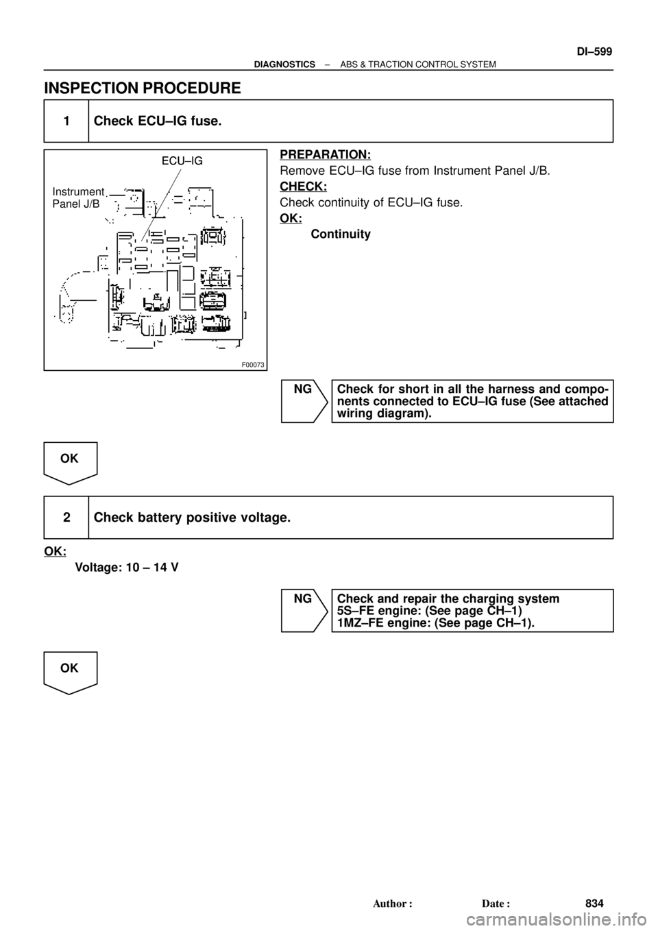
INSPECTION PROCEDURE
1 Check ECU±IG fuse.
PREPARATION:
Remove ECU±IG fuse from Instrument Panel J/B.
CHECK:
Check continuity of ECU±IG fuse.
OK:
Continuity
NG Check for short in all the harness and compo-
nents connected to ECU±IG fuse (See attached
wiring diagram).
OK
2 Check battery positive voltage.
OK:
Voltage: 10 ± 14 V
NG Check and repair the charging system
5S±FE engine: (See page CH±1)
1MZ±FE engine: (See page CH±1).
OK
Page 1814 of 4592

F00062
ECMABS & TRAC ECU
NEONEO
E8
A16BR±W15 ECMABS & TRAC ECU
NEONEOA16BR±W15 ECMABS & TRAC ECU
NEONEOA16BR±W15 ECMABS & TRAC ECU
NEONEOA16BR±W15
ECMABS & TRAC ECU
NEONEO
A16BR±W15
16
DI±602
± DIAGNOSTICSABS & TRACTION CONTROL SYSTEM
837 Author�: Date�:
DTC 44 NE Signal Circuit
CIRCUIT DESCRIPTION
The ABS & TRAC ECU receives engine speed signals (NE signals) from the ECM.
DTC No.DTC Detecting ConditionTrouble Area
44
Condition 1. or 2. is detected:
1. TRAC is in operation and engine speed is 0 rpm contin-
ues for 2.4 sec. or more.
2. TRAC is in non±operation, sift lever is not in P or N posi-
tion, both the front right and left wheels' speed is 30
km/h (19 mph) or more, engine speed is 0 rpm and does
not have communication malfunction, and malfunction
information of engine system is OFF.
�NEO circuit
�ECM
�ECU
WIRING DIAGRAM
INSPECTION PROCEDURE
1 Check for open and short circuit in harness and connector between terminal
NEO of ABS & TRAC ECU and terminal NEO of ECM (See page IN±31).
NG Repair or replace harness or connector.
OK
DI04P±04
Page 1816 of 4592
F00124
STOP 7
1C4 W
1R Stop
Light
SwitchJ28
5
2ABS & TRAC ECU
A16
Instrument Panel J/B
F91B
1G±WJ27
1SSTP
F4
ALTB±RJ/C
C
A16
R117
5
BP
R9 W±B
Battery MAIN FL Block
BL
B±G1 11R
42 Instrument
Panel J/BG±W
G±W
G±W
Light
Failure
Sensor
Right
Stop
Light High
Mounted
Stop
Light
J40Left
Stop
Light R
H102 1
H10R11R9
1 22
2
5 W±BW±B
W±B
W±B W±B W±B
W±B J/CA
A DI±604
± DIAGNOSTICSABS & TRACTION CONTROL SYSTEM
839 Author�: Date�:
DTC 49 Stop Light Switch Circuit
CIRCUIT DESCRIPTION
DTC No.DTC Detecting ConditionTrouble Area
49
Battery voltage has never exceeded more than 17.0 V and
become less than 9.5 V within 2.16 sec. and the STP
terminal voltage of ECU is under open circuit detecting
limits continues for 3 sec. or more.�Stop light switch
�Stop light switch circuit
�ECU
WIRING DIAGRAM
DI04Q±04
Page 1818 of 4592
F03413
ALTEngine Room R/B No. 3
2ABS & TRAC
Motor Relay
A8ABS & TRAC ActuatorABS
4
W±R
MTR+ GR±L
14 24
MR A15
13
F5
F4
B±GFL
Block
MAIN
Battery
EA 1 B±G
333
1
2
3
A8A8
1 23
W±BA15
A15 GR±R
R±W 1ABS & TRAC ECU
1 DI±606
± DIAGNOSTICSABS & TRACTION CONTROL SYSTEM
841 Author�: Date�:
DTC 51 ABS Pump Motor Lock
CIRCUIT DESCRIPTION
DTC No.DTC Detecting ConditionTrouble Area
51
In the midst of initial check, after the current flows to the
motor for 3 sec. and motor relay is turned OFF , then
within 0.66 sec., the condition that the motor relay
monitor is OFF continues for 0.24 sec. or more.
�ABS pump motor
Fail safe function:
If any trouble occurs in the ABS & TRAC pump motor, the ECU cuts off current to the ABS & TRAC solenoid
relay and prohibits ABS control and TRAC control.
WIRING DIAGRAM
DI4KX±01
Page 1820 of 4592

F00063
ECMABS & TRAC ECU
EFI+
EFI±
TRC+
TRC±EFI+
EFI±
TRC+
TRC±
E7
E7
E7
E7A16
A16
A16
A1614 6
14
13
5W
B
L ECMABS & TRAC ECU
EFI+
EFI±
TRC+
TRC±EFI+
EFI±
TRC+
TRC±E7
E7
E7
E7A16
A16
A16
A16
21
206
14
13
5
W
B
L ECMABS & TRAC ECU
EFI+
EFI±
TRC+
TRC±EFI+
EFI±
TRC+
TRC±E7
E7
E7
E7A16
A16
A16
A166
14
13
5W
B
L
ECMABS & TRAC ECU
EFI+
EFI±
TRC+
TRC±EFI+
EFI±
TRC+
TRC±
E7
E7
E7
E7A16
A16
A16
A166
14
13
5W
B
LG
L
13
DI±608
± DIAGNOSTICSABS & TRACTION CONTROL SYSTEM
843 Author�: Date�:
DTC 53 ECM Communication Circuit Malfunction
CIRCUIT DESCRIPTION
This circuit is used to send TRAC control information from the ABS & TRAC ECU to the ECM (TRC+, TRC±),
and engine control information from the ECM to the ABS & TRAC ECU (EFI+, EFI±).
DTC No.DTC Detecting ConditionTrouble Area
53ECM communication data malfunction is detected.
�TRC+ or TRC± circuit
�EFI+ or EFI± circuit
�ECM
�ECU
WIRING DIAGRAM
INSPECTION PROCEDURE
1 Check for open and short circuit in harness and connector between terminals
EFI+, EFI±, TRC+, TRC± of ABS & TRAC ECU and ECM (See page IN±31).
NG Repair or replace harness or connector.
OK
Check and replace ECM or ABS & TRAC ECU.
DI04S±04