Page 1668 of 4592

DI1KB±01
A00223
Vehicle Speed
Sensor4±Pulse
Combination
Meter
ECM
Transaxle
Vehicle Speed Sensor
4±Pulse
Q00515 Q00514
DI±456
± DIAGNOSTICSAUTOMATIC TRANSAXLE (A541E)
691 Author�: Date�:
CIRCUIT INSPECTION
DTC P0500 Vehicle Speed Sensor Malfunction
CIRCUIT DESCRIPTION
The vehicle speed sensor outputs a 4±pulse signal for every revolution of the rotor shaft, which is rotated
by the transmission output shaft via the driven gear. After this signal is converted into a more precise rectan-
gular waveform by the waveform shaping circuit inside the combination meter, it is then transmitted to the
ECM. The ECM determines the vehicle speed based on the frequency of these pulse signals.
DTC No.DTC Detecting ConditionTrouble Area
P0500
No vehicle speed sensor signal to ECM under conditions (a)
and (b)
(2 trip detection logic)
(a) Park/neutral position switch is OFF
(b) Vehicle is being driven�Open or short in vehicle speed sensor circuit
�Vehicle speed sensor
�Combination meter
�ECM
At ti t l (lthb k t )Clutch or brake slips or gear is broken�Automatic transaxle (clutch, brake or gear etc.)
WIRING DIAGRAM
See page DI±333.
Page 1675 of 4592
D01092
Transaxle
*1: Except California, w/ Engine Immobilizer and / or TRAC
*2: California, w/ Engine Immobilizer and / or TRACShift Solenoid
Valve No.1
W3
6 E3
L±B BV
J/C J26
A*2 *1
Shift Solenoid
Valve No.2
E3A
AL±BE11
E10 7
11
817
E10
E11 *2 *1ECM
B+
S1
S2B+
Cruise Control ECU
Q07642D00833D01909
California, w/ Engine Immobilizer
and / or TRAC:S1
S2
S1
S2
Except California, w/ Engine Immobilizer
and / or TRAC:
± DIAGNOSTICSAUTOMATIC TRANSAXLE (A541E)
DI±463
698 Author�: Date�:
WIRING DIAGRAM
INSPECTION PROCEDURE
1 Measure resistance between terminal S1 or S2 of ECM and body ground.
PREPARATION:
Disconnect the connector from ECM.
CHECK:
Measure resistance between terminal S1 or S2 of ECM and
body ground.
OK:
Resistance: 11 ~ 15 W
Page 1680 of 4592

D01093
Transaxle
Shift Solenoid
Valve SL
2
E3P±L
E10B+
SLECM
*1: Except California, w/ Engine Immobilizer and / or TRAC
*2: California, w/ Engine Immobilizer and / or TRACE11 *2*1
27
9
Y DI±468
± DIAGNOSTICSAUTOMATIC TRANSAXLE (A541E)
703 Author�: Date�:
DTC P0773 Shift Solenoid E Electrical Malfunction
(Shift Solenoid Valve SL)
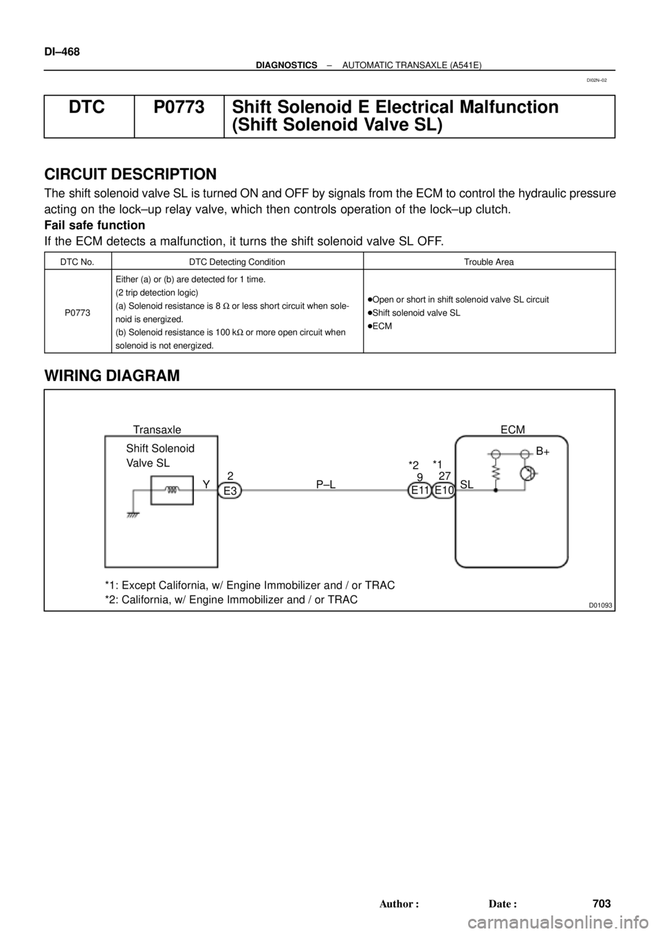
CIRCUIT DESCRIPTION
The shift solenoid valve SL is turned ON and OFF by signals from the ECM to control the hydraulic pressure
acting on the lock±up relay valve, which then controls operation of the lock±up clutch.
Fail safe function
If the ECM detects a malfunction, it turns the shift solenoid valve SL OFF.
DTC No.DTC Detecting ConditionTrouble Area
P0773
Either (a) or (b) are detected for 1 time.
(2 trip detection logic)
(a) Solenoid resistance is 8 W or less short circuit when sole-
noid is energized.
(b) Solenoid resistance is 100 kW or more open circuit when
solenoid is not energized.
�Open or short in shift solenoid valve SL circuit
�Shift solenoid valve SL
�ECM
WIRING DIAGRAM
DI02N±02
Page 1684 of 4592
DI±472
± DIAGNOSTICSAUTOMATIC TRANSAXLE (A541E)
707 Author�: Date�:
DTC P1520 Stop Light Switch Signal Malfunction
CIRCUIT DESCRIPTION
The purpose of this circuit is to prevent the engine from stalling, while driving in lock±up condition, when
brakes are suddenly applied.
When the brake pedal is operated, this switch sends a signals to ECM. Then the ECM cancels operation
of the lock±up clutch while braking is in progress.
DTC No.DTC Detecting ConditionTrouble Area
P1520No stop light switch signal to ECM during driving.
(2 trip detection logic)�Open or short in stop light switch circuit
�Stop light switch
�ECM
WIRING DIAGRAM
See page DI±363.
INSPECTION PROCEDURE
See page DI±363.
DI02O±02
Page 1685 of 4592

Q04869
NC2 Revolution Sensor
D01094
Direct Clutch
Speed Sensor 2V3
1
V3
G R
E99
E94ECM
NC2
+
NC2±4 ~ 6 V
*1: Except California, w/ Engine Immobilizer and / or TRAC
*2: California, w/ Engine Immobilizer and / or TRAC*2 *1
E1114
26 *2 *1
E11
± DIAGNOSTICSAUTOMATIC TRANSAXLE (A541E)
DI±473
708 Author�: Date�:
DTC P1705 NC2 Revolution Sensor Circuit Malfunction
(Direct Clutch Speed Sensor)
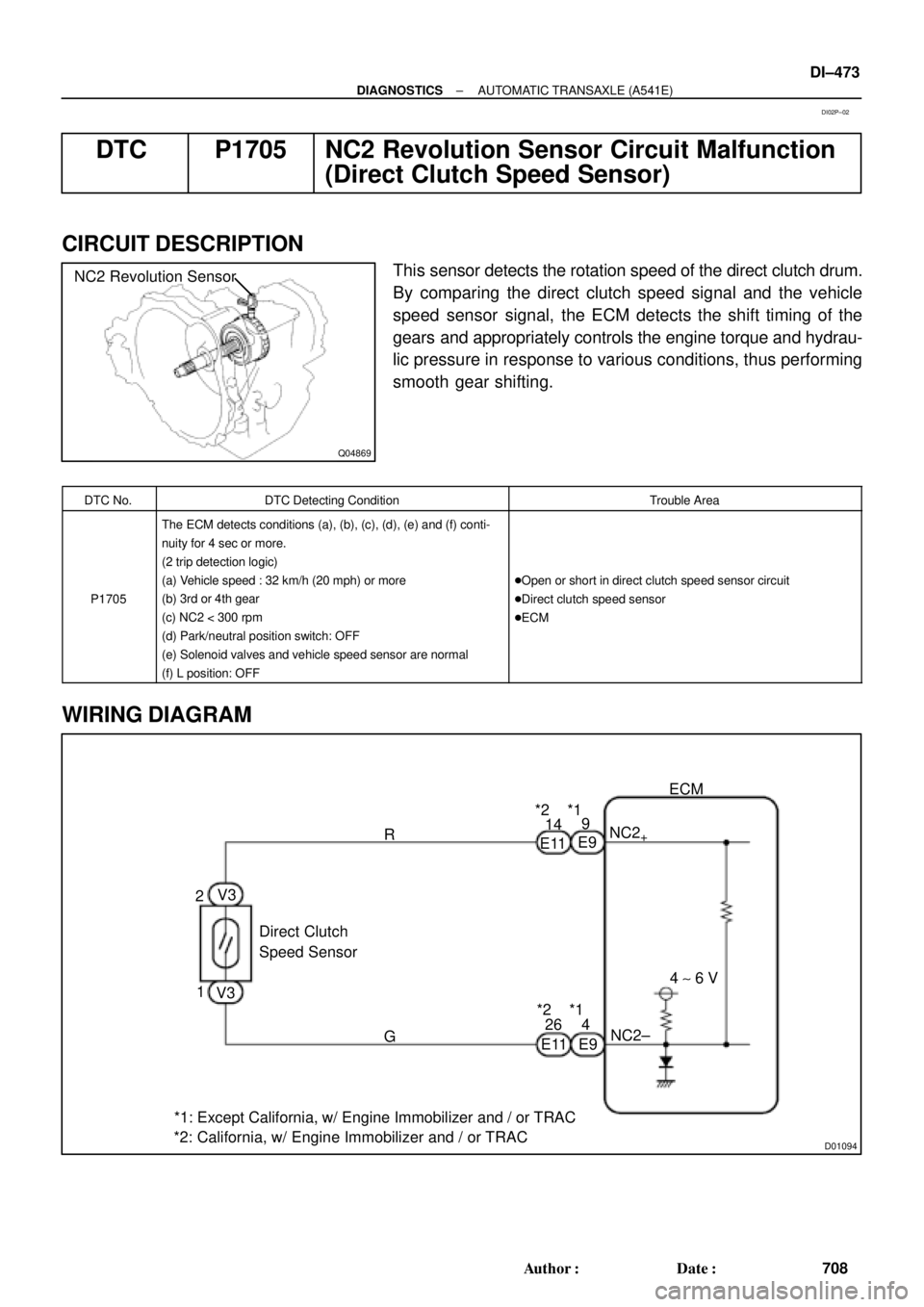
CIRCUIT DESCRIPTION
This sensor detects the rotation speed of the direct clutch drum.
By comparing the direct clutch speed signal and the vehicle
speed sensor signal, the ECM detects the shift timing of the
gears and appropriately controls the engine torque and hydrau-
lic pressure in response to various conditions, thus performing
smooth gear shifting.
DTC No.DTC Detecting ConditionTrouble Area
P1705
The ECM detects conditions (a), (b), (c), (d), (e) and (f) conti-
nuity for 4 sec or more.
(2 trip detection logic)
(a) Vehicle speed : 32 km/h (20 mph) or more
(b) 3rd or 4th gear
(c) NC2 < 300 rpm
(d) Park/neutral position switch: OFF
(e) Solenoid valves and vehicle speed sensor are normal
(f) L position: OFF
�Open or short in direct clutch speed sensor circuit
�Direct clutch speed sensor
�ECM
WIRING DIAGRAM
DI02P±02
Page 1689 of 4592
D01095
Shift Solenoid
Valve SLN 1
4
B±YW±L3
2
SLN
±
SLN+
ECM
*1: Except California, w/ Engine Immobilizer and / or TRAC
*2: California, w/ Engine Immobilizer and / or TRAC*2 *1
E11
E3E10
E9 E3*2 *1
1920
R
L
E11
D00050
2
1
21
± DIAGNOSTICSAUTOMATIC TRANSAXLE (A541E)
DI±477
712 Author�: Date�:
WIRING DIAGRAM
INSPECTION PROCEDURE
1 Check shift solenoid valve SLN.
PREPARATION:
Disconnect the shift solenoid valve SLN connector.
CHECK:
(a) Measure resistance between terminals 1 and 2 of sole-
noid connector.
(b) Connect positive � lead with an 8 ~10 W bulb to terminal
1 of solenoid connector and negative ��lead to terminal
2, then check the movement of the valve.
OK:
(a) Resistance: 5.1 ~ 5.5 W
(b)
When battery positive voltage is applied.Valve move in direction in illustration.
(on the left)
When battery positive voltage is cut off.Valve move in direction in illustration.
(on the right)
Page 1692 of 4592

D01897
Combination Meter
Ignition Switch Except California, w/ Engine Immobilizer and / or TRAC:
R
2
L8
11
6 C8
13
165
R±B
L±W YIJ1
IG310
1H
1VECM
1
E7
B+ 4
II2 P1
II3D J/C J2910 C8
C8O
Y
R±BY
R 2L
E7
E7
E10 II2 P1
P1
P1D D
J/C J29 E
15
14
B±W A
GR3
6CL±W (*1, *3)
O (*2, *4) LL
2L
RL R±L
J27J28
J/C
10FE E Y
Y
L±W L±W6 5
8
R±BR±BR±B
5
P1 P12
AJ/C
J24
R±LA J27
C
B±W
B
BB
J/C J26
B±W
II2II22
R±L
J28J/C J28
F
J2811
II2
B±WBBJ/C J29NSW
R±L
B±W 1
1
GAUGE
1K 1J I16 I16
I16 I16
1J 1K3
4 Starter B±Y
R 4
8 2
7IG1
AM1
ST2
AM2 1B
2L 2AW
W±R 2
1K AM1
2 1 1
1B 1K5 5
GR (*4)
B±O (*5)
W±R
41
AM2
B
B B±R
B±R
B±R
1
2 F9
F9
ALT
11F4
F6
B±G
BatteryB
C
J8J7GR (*4)
B±O (*5)3
1
2535
2B
2D
2J
2K 11
12
ST
Relay
B±R
Starter
W±BAJ/C J11
IG
Left Kick
Panel Park/Neutral Position Switch
9
J/C CInstrument Panel J/B
Fusible
Link BlockEngine Room J/B No.2
MAIN 3
FL
Main
*1: w/ Engine Immobilizer System
*2: w/o Engine Immobilizer System
*3: TMC Made Ex. USA w/ TRAC
*4: TMMK Made, TMC Made USA w/ TRAC DI±480
± DIAGNOSTICSAUTOMATIC TRANSAXLE (A541E)
715 Author�: Date�:
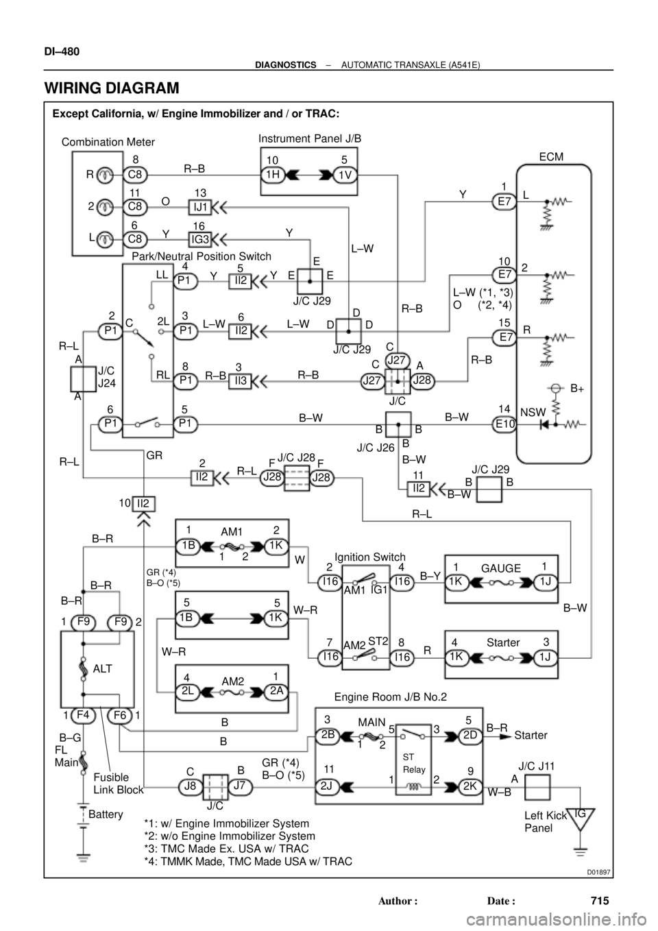
WIRING DIAGRAM
Page 1696 of 4592
D01899
Cruise Control ECU
14
ODY±B7B+
OD1ECM
C15
E10E7
*1: Except California, w/ Engine Immobilizer and / or TRAC
*2: California, w/ Engine Immobilizer and / or TRAC*2
*1
24 DI±484
± DIAGNOSTICSAUTOMATIC TRANSAXLE (A541E)
719 Author�: Date�:
O/D Cancel Signal Circuit
CIRCUIT DESCRIPTION
While driving uphill with cruise control activated, in order to minimize gear shifting and provide smooth cruis-
ing overdrive may be prohibited temporarily under some condition.
The cruise control ECU sends O/D cut signals to the ECM as necessary and the ECM cancels overdrive
shifting until these signals are discontinued.
WIRING DIAGRAM
DI02S±02