Page 1578 of 4592

601 Author�: Date�:
DTC P1600 ECM BATT Malfunction
CIRC")
S05470
Battery FL
MAIN B±G
F4
F61 1
18
B Fusible
Link
BlockEngine Room J/B No.2
2A2JB±YECM
BATT EFI
E71 DI±366
± DIAGNOSTICSENGINE (1MZ±FE)
601 Author�: Date�:
DTC P1600 ECM BATT Malfunction
CIRCUIT DESCRIPTION
Battery positive voltage is supplied to terminal BATT of the ECM even when the ignition switch is OFF for
use by the DTC memory and air±fuel ratio adaptive control value memory, etc.
DTC No.DTC Detecting ConditionTrouble Area
P1600Open in back up power source circuit�Open in back up power source circuit
�ECM
HINT:
If DTC P1600 appear, the ECM does not store another DTC.
WIRING DIAGRAM
INSPECTION PROCEDURE
HINT:
Read freeze frame data using TOYOTA hand±held tester or OBD II scan tool. Because free frame records
the engine conditions when the malfunction is detected, when troubleshooting it is useful for determining
whether the vehicle was running or stopped, the engine warmed up or not, the air±fuel ratio lean or rich, etc.
at the time of the malfunction.
DI089±06
Page 1580 of 4592

603 Author�: Date�:
DTC P1780 Park/Neutral Position Switch Malfunction
CIRCUIT DESCRIPTION
The park/neutral position switch go on when the shift lever is in the")
DI±368
± DIAGNOSTICSENGINE (1MZ±FE)
603 Author�: Date�:
DTC P1780 Park/Neutral Position Switch Malfunction
CIRCUIT DESCRIPTION
The park/neutral position switch go on when the shift lever is in the N or P shift position. When it goes on
terminal NSW of the ECM is grounded to body ground via the starter relay, thus the terminal NSW voltage
becomes 0V. When the shift lever is in the D, 2, L or R position, the park/neutral position switch goes off,
so the voltage of ECM. Terminal NSW becomes battery voltage, the voltage of the ECM internal power
source. If the shift lever is moved from the N position to the D position, this signal is used for air±fuel ratio
correction and for idle speed control (estimated control), etc.
DTC No.DTC Detecting ConditionTrouble Area
2 or more switches are ON simultaneously for ºNº, º2º, ºLº and
ºRº positions
(2 trip detection logic)
Sh t i k/ t l iti it h i it
P1780When driving under conditions (a) and (b) for 30 sec. or more
the park/neutral position switch is ON (N position):
(2 trip detection logic)
(a) Vehicle speed: 70 km/h (44 mph) or more
(b) Engine speed: 1,500 � NE and 2,500 rpm�Short in park/neutral position switch circuit
�Park/neutral position switch
�ECM
HINT:
After confirming DTC P1780, use the TOYOTA hand±held tester to confirm the PNP switch signal from
ºCURRENT DATAº.
WIRING DIAGRAM
Refer to DTC P1780 on page DI±479.
INSPECTION PROCEDURE
Refer to DTC P1780 (Park/Neutral Position Switch Malfunction) on page DI±479.
HINT:
Read freeze frame data using TOYOTA hand±held tester or OBD II scan tool. because freeze frame records
the engine conditions when the malfunction is detected, when troubleshooting it is useful for determining
whether the vehicle was running or stopped, the engine warmed up or not, the air±fuel ratio lean or rich, etc.
at the time of the malfunction.
DI08A±06
Page 1581 of 4592

A07450
Ignition SwitchW±R B±RInstrument Panel J/B
FL
MAINFusible
Link
Block
BatteryJunction
ConnectorECM
B±R
W±R
BR
BR
W±B
B±Y
B
6
7
2 4
17
2 5
4
1 1B
AA F4 F6 E10E7
2F 2K 2J
2L
2AEFI EFI
RelayEngine Room
J/B+B
E1 17 16
AM2
EB EC
J28
3
1E72
MREL
E78IGSW
J27
1W
1B7
5 IGN
1K3
1K5
B+ B
B±Y
B±W
B±W
J35 J35
C
C
Junction
Connector
B±GJ22
Junction
Connector
± DIAGNOSTICSENGINE (1MZ±FE)
DI±369
604 Author�: Date�:
ECM Power Source Circuit
CIRCUIT INSPECTION
When the ignition switch is turned on, battery positive voltage is applied to terminal IGSW of the ECM and
the EFI main relay (Marking: EFI) control circuit in the ECM sends a signal to terminal MREL of the ECM
switching on the EFI main relay.
This signal causes current to flow to the coil, closing the contacts of the EFI, main relay and supplying power
to terminals +B of the ECM.
If the ignition switch is turned off, the ECM continues to switch on the EFI main relay for a maximum of 2
seconds for the initial setting of the IAC valve.
WIRING DIAGRAM
DI4DU±01
Page 1583 of 4592
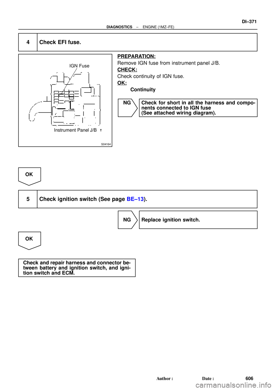
S04164
IGN Fuse
Instrument Panel J/B
± DIAGNOSTICSENGINE (1MZ±FE)
DI±371
606 Author�: Date�:
4 Check EFI fuse.
PREPARATION:
Remove IGN fuse from instrument panel J/B.
CHECK:
Check continuity of IGN fuse.
OK:
Continuity
NG Check for short in all the harness and compo-
nents connected to IGN fuse
(See attached wiring diagram).
OK
5 Check ignition switch (See page BE±13).
NG Replace ignition switch.
OK
Check and repair harness and connector be-
tween battery and ignition switch, and igni-
tion switch and ECM.
Page 1584 of 4592
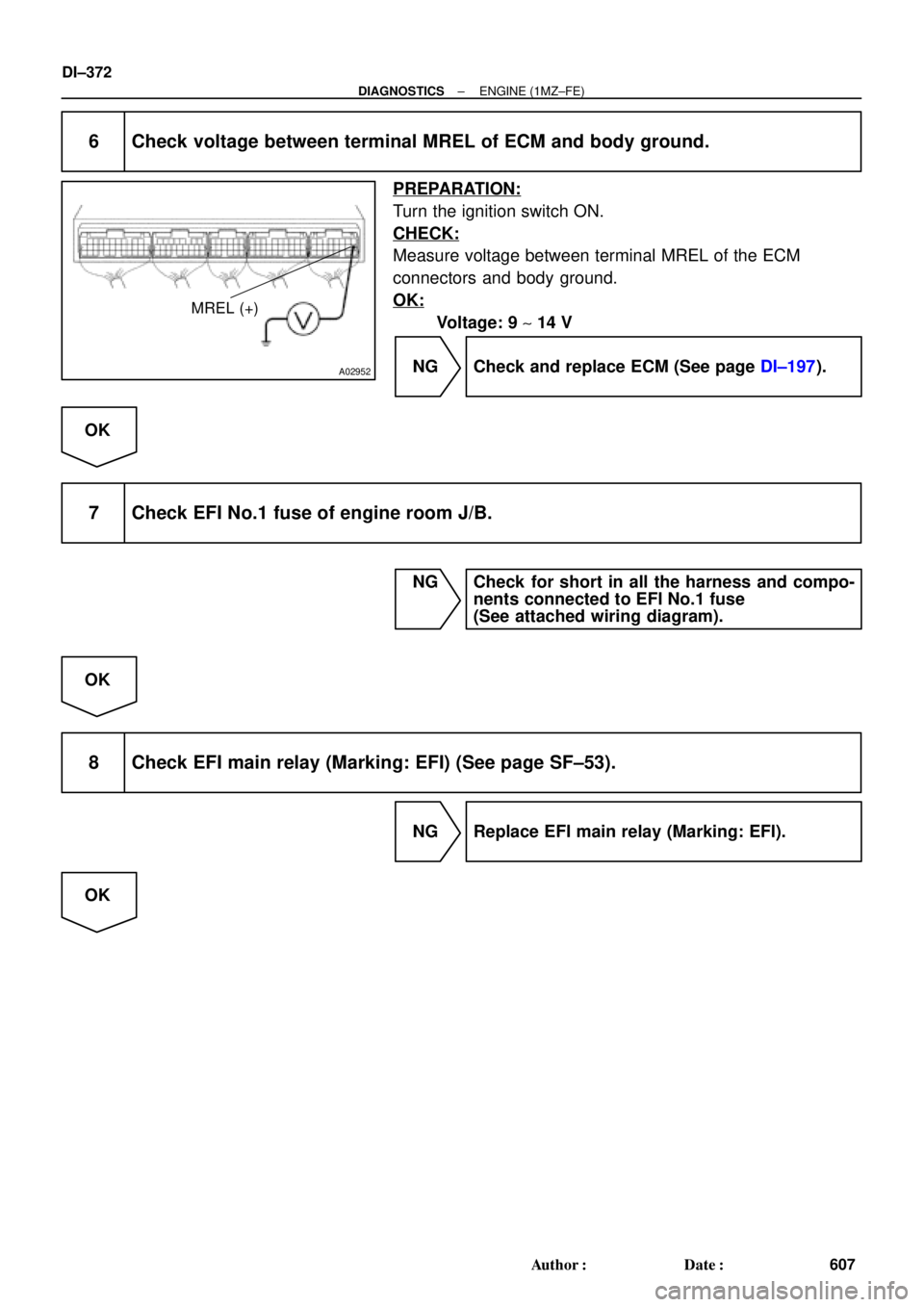
A02952
MREL (+)
DI±372
± DIAGNOSTICSENGINE (1MZ±FE)
607 Author�: Date�:
6 Check voltage between terminal MREL of ECM and body ground.
PREPARATION:
Turn the ignition switch ON.
CHECK:
Measure voltage between terminal MREL of the ECM
connectors and body ground.
OK:
Voltage: 9 ~ 14 V
NG Check and replace ECM (See page DI±197).
OK
7 Check EFI No.1 fuse of engine room J/B.
NG Check for short in all the harness and compo-
nents connected to EFI No.1 fuse
(See attached wiring diagram).
OK
8 Check EFI main relay (Marking: EFI) (See page SF±53).
NG Replace EFI main relay (Marking: EFI).
OK
Page 1586 of 4592
A07151
Fuel Pump Circuit Opening Relay
EFI Main Relay
FC
Tr
MREL
IGSW
STA EFI
NEECM
Starter Starter Relay MAIN
Battery AM2IG Switch
(NE Signal) (STA Signal) Park/ Neutral Position Switch IGN
STARTER DI±374
± DIAGNOSTICSENGINE (1MZ±FE)
609 Author�: Date�:
Fuel Pump Control Circuit
CIRCUIT DESCRIPTION
In the diagram below, when the engine is cranked, current flows from terminal ST of the ignition switch to
the starter relay coil and also current flows to terminal STA of ECM (STA signal).
When the STA signal and NE signal are input to the ECM, Tr is turned ON, current flows to coil of the circuit
opening relay, the relay switches on, power is supplied to the fuel pump and the fuel pump operates.
While the NE signal is generated (engine running), the ECM keeps Tr ON (circuit opening relay ON) and the
fuel pump also keeps operating.
DI4DV±01
Page 1587 of 4592
A07451
ECM
E01 FC 3
E7
G±R
5EB1
G±R 1
1
1 1 15
3
2
CIR OPN Relay
Engine Room R/B
L±B
EB1
ID1L±B
A
A
5 4 10
7
W±B
W±BJ11
Junction
Connector
IG BL
StarterS2
B±R
EB
B±R 2D
2K 2F
9 5 4 2C 10
II2
10
Junction
Connector
J8 J7
C B(A/T)
(A/T) GR
(M/T) B±WPark/
Nutral
Position
Switch
6 5(A/T)
B±W(A/T)
B±WII2
11 11
ST Relay
B B
B EFI Relay23
15
2
13 5
2J 2K
W±BB±R W±B B±RB±W
7 8R1K
W±R
1J
43
1B
STARTER
5 5
1
2 B±W
W±B
2A
2B31
2L 4 AM27Instrument Panel J/B
Battery
B±GFL
MAIN F6
F4 1
Fusible
Link
BlockB B
EFI
MAINB+
MREL
8
E7
B±R
Fuel
Pump
1W 1K1
IGN
1
ST2
IG2
AM2Clutch
Start
Switch
L±BW±B
Junction
Connector
A
J40
Junction
Connector
1K 7
*B±O *1GR
(M/T)
*B±O *1GR
J35 J35C
*B±O *1GR
B±W
B±R
Junction
Connector J26
1
7
3
1K
*: TMMK made
*
1: TMC made
± DIAGNOSTICSENGINE (1MZ±FE)
DI±375
610 Author�: Date�:
WIRING DIAGRAM
Page 1592 of 4592
A00306
135
24 6 IACVIACV closed (VSV: ON)
Throttle Valve30°
3,700 rpm
Engine speed
Throttle valve
opening angle
FI7011 FI6570
A07452
From Battery 2J2
W±B
B±Y
J20
Junction
Connector 9
AAECMACIS
12
MRELB±W
VSV for ACIS
R±Y B±Y 17
2K
2A 2F
51 2
3 4Engine Room J/B
EFI
EBJunction
Connector BB+
B±Y178
E11E7
B
B±YE01
B±W
J36 J35CC
EFI Relay
J27 J28
II3Junction Connector DI±380
± DIAGNOSTICSENGINE (1MZ±FE)
615 Author�: Date�:
IACV Control VSV Circuit
CIRCUIT DESCRIPTION
This circuit opens and closes the IACV (Intake Air Control Valve) in response to the engine load in order to
increase the intake efficiency (ACIS: Acoustic Control Induction System).
When the engine speed is 3,700 rpm or less and the throttle valve opening angle is 60° or more, the ECM
turns the VSV ON and closes the IACV. At all other times, the VSV is OFF, so the IACV is open.
WIRING DIAGRAM
DI08E±06
 (STA Signal) Park/ Neutral Position Switch IGN
STARTER D")


Throttle Valve30°
3,700 rpm
Engine speed
Throttle valve
opening angle
FI7011 FI6570
A07452
From Battery 2J2
W±B
B±Y
J20
Junction
Connector 9
AAECMACIS
12")